 2020, Vol. 31


b State Key Laboratory of Silicon Materials, Key Laboratory of Advanced Materials and Applications for Batteries of Zhejiang Province, Department of Materials Science and Engineering, Zhejiang University, Hangzhou 310027, China;
c Key Laboratory of Advanced Energy Materials Chemistry(Ministry of Education), College of Chemistry, Nankai University, Tianjin 300071, China
Electrochemical oxygen evolution reaction (OER) is regarded as one of the most important technologies to produce green combustion improver [1-5]. It is widely known that the OER efficiency and corresponding energy consumption largely depend on the physicochemical and electrochemical properties of electrocatalysts [6, 7]. Despite excellent OER performance, IrO2- [8] and RuO2-based catalysts [9, 10] still cannot be accepted by the market because of their compromised durability, scarcity, and high cost [11]. Hence, cost-effective alternatives such as transition metals [12], metal hydroxides [13], metal oxides [14] and metal nitrides [15], have been widely explored to obtain OER high-performance. Among them, nickel-based electrocatalysts stand out above owing to their natural abundance, low cost, good electrochemical reactivity, favorable conductivity, and outstanding stability [16]. Generally, two symbiotic strategies (conductive matrix composite and heteroatom doping) are employed to achieve optimized performance [17-19].
Transition Ni oxides and hydroxides (NiO, Ni(OH)2, etc.) have been widely investigated as electrocatalysts of OER [20], but it is a pity that their electrical conductivity is intrinsically low, leading to compromised OER performance. Given all that, it is worth noting that transition metals (e.g., Ni) are more attractive when applied in OER because of their high electrical conductivity and excellent electrocatalytic activity [21]. Currently, a wide range of transition metal particles and composites has been fabricated via different methods. For example, Chen et al. [22] fabricated a Ni/graphene catalyst by using N-doped graphene film as matrix and achieved enhanced OER activity. Despite these efforts, their OER activities are still not satisfactory because the mentioned Ni-based materials are prone to aggregate under high temperature resulting in decreased active area and undermined electrocatalytic performance. In addition, their synthetic procedure is tedious and needs multi-step process. Therefore, a powerful and facile fabrication method is desirable to construct advanced Ni/carbon composites with good advantages including uniform distribution, no aggregation, large surface area, good structural stability and fast ion/electron transfer path.
Fortunately, puffing method has been proven as a powerful way to prepare homogeneous carbon-based materials with tunable structure and components [23]. Typically, rice can be effectively puffed to form hierarchical porous carbon and proven by our previous work on lithium sulfur batteries. On the other hand, it is well accepted that, comparable to pure carbon, heteroatom-doped carbon matrix is more favorable owing to its boosted conductivity and higher reactivity as well as lower adsorption energy for ions [14, 24]. However, up to now, there is no work on controllable synthesis of porous N-doped puffed carbon with embedding Ni. And their OER performance is still unknown.
Herein, we report a powerful puffing method to fabricate hierarchical porous N-doped carbon with numerous embedded Ni nanoparticles. Interestingly, rice first adsorbs aniline (N sources) and NiCl2 (Ni source), and then the sample is converted into Niembedded N-doped porous carbon (N-PC/Ni) after puffing process and heat treatment [25, 26]. The N-PC/Ni composite shows a crosslinked porous architecture with conductive N-doped carbon backbone and the embedded nickel nanoparticles can serve as efficient active electrocatalysts for OER. Carbothermic reduction is proposed to illustrate the pore formation mechanism in N-PC/Ni composite. Consequently, the designed N-PC/Ni composite shows advantages including large surface area, highly porous structure, and enhanced conductivity. Accordingly, the N-PC/Ni composite exhibits superior OER performance with a low Tafel slope (~88 mV/dec) and a low overpotential. Our work shows a new route to design and fabricate metal/heteroatom-doped composites as advanced electrocatalysts for electrocatalysis.
Fig. 1a shows the facile fabrication process of N-PC/Ni composite via a puffing process. It is seen that soaked rice with NiCl2 (Ni source) and aniline (N source) can be in-situ converted into N-PC/Ni composite. In our case, the N-PC is prepared in a heated sealed pressure vessel at 250 ℃ and 1.5 MPa. The whole puffing reaction is high-efficiency and only takes about 5 min. Followed by the annealing process, numerous nickel nanoparticles are successfully embedded into the N-PC matrix with lots of secondary pores, forming the final N-PC/Ni composite.

|
Download:
|
| Fig. 1. (a) Fabrication process of N-PC/Ni composite. (b, c) SEM images of N-PC. (d, e) TEM and HRTEM images of N-PC. | |
Scanning electron microscopy (SEM) images of N-PC are presented in Figs. 1b and c. The N-PC exhibits a 3D porous architecture, which remains well after carbonization process. Interestingly, the N-PC shows a cross-linked porous structure with boundary thickness of ~500 nm. This structure possesses various pore sizes and the large pore size in the N-PC is about 100 μm. Interconnected porous structure can ensure sprawling networks for fast diffusion of ions and rapid transfer of electrons. This is favorable to achieve fast reaction kinetics and high utilization of active sites [27]. Further investigation on the microstructure of NPC is conducted by transmission electron microscopy (TEM) and high-resolution transmission electron microscopy (HRTEM) images (Figs. 1d and e). The smooth texture of carbon flakes is clearly noticed in TEM image (Fig. 1c). Additionally, the amorphous nature of the N-PC is confirmed by e selected area electron diffraction (SEAD) pattern and poor crystalline lattice fringe in HRTEM image (Fig. 1e).
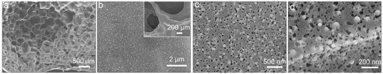
SEM images of N-PC/Ni composites are shown in Fig. 2. The 3D porous structure is still well preserved after puffing-annealing process (Fig. 2a). The as-obtained N-PC/Ni composites display a highly porous structure with cross-linked shells (Fig. 2b). Notice that all the pores in the N-PC/Ni are uniformly linked together and extended in all directions, forming a 3D interconnected porous network. As clearly shown in Fig. 2c, the porous surface contains numerous pores ranging from 5 nm to 10 nm and the embedded nickel particles have diameters of 15-50 nm. The nickel nanoparticles are distributed in both internal and surface (Fig. 2d). It should be mentioned that the tiny pores are generated by the introduction of nickel due to carbothermic reduction. The NiCl2 reacts with the carbon sources and etch the N-PC to produce new mesopores, which can further increase the surface area and active sites [28, 29].

|
Download:
|
| Fig. 2. SEM images of N-PC/Ni composites (fine structure in inset). Scale bar: (a) 500 μm, (b) 2 μm, (c) 500 nm, (d) 200 nm. | |
The composite structure was further distinguished by TEM images (Figs. 3a and b). It is seen that Ni nanoparticles have diameters of 15-50 nm and are well distributed in the N-PC framework. The high crystallinity of Ni particles is strongly supported by selected area electron diffraction (SAED) pattern (inset in Fig. 3c) and high-resolution TEM image (inset in Fig. 3d). The characteristic (200), (111) and (200) planes of Ni phase are detected in the SAED pattern. The clear attice distance of ~0.20 nm is corresponding to the (111) crystal plane of cubic Ni phase. In addition, the N-PC matrix embedded with Ni nanoparticles are also supported by energy dispersive spectrometer (EDS) elemental mapping images, which verify the homogeneous distribution of C, O and N elements.

|
Download:
|
| Fig. 3. (a–d) TEM-HRTEM images and SAED pattern of N-PC/Ni composite. (e) EDS elemental mapping images of Ni, C, O and N of N-PC/Ni composite. | |
Detailed phases were characterized by X-ray diffraction (XRD) and Raman tests. Fig. 4a shows the typical XRD patterns of N-PC and N-PC/Ni samples. The N-PC shows a broad peak located at 23° due to (002) crystal planes of the low-crystallized carbon phase (JCPDS No. 75-1621). For the N-PC/Ni sample, except for the diffraction peaks of N-PC matrix, three diffraction peaks which are characteristic of cubic Ni phase (JCPDS No. 04-0850) are observed, confirming the successful fabrication and implantation of Ni into N-PC matrix. These results are also confirmed by Raman (Fig. 4b). All the samples exhibit two typical Raman peaks located at 1338 and 1585 cm-1, which can be indexed with the D-band and G-band of N-PC matrix. BET measurements were implemented to examine the porous nature and illustrate the surface area of samples. The N2 adsorption/desorption isotherm curves are shown in Fig. 4c. The as-prepared N-PC/Ni composite exhibits a larger specific surface area (~655 m2/g) than that of N-PC counterpart (~220 m2/g).

|
Download:
|
| Fig. 4. Phase and composition characterization: (a) XRD patterns; (b) Raman spectra; (c) N2 adsorption/desorption isotherm curves of N-PC and N-PC/Ni samples. | |
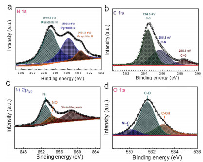
Chemical composition of N-PC/Ni sample was also characterized by XPS spectra. The N 1s spectrum of N-PC/Ni (Fig. 5a) contains three different N-doping forms, including pyridinic-N, pyrrolic-N and graphitic-N [22]. The pyridinic-N at 398.5 eV dominates the majority while the peaks located at 400.3 eV and 401.3 eV belong to pyrrolic-N and graphitic-N, respectively. The C 1s spectrum (Fig. 5b) shows two peaks at 284.5 and 288.8 eV corresponding to the C—C and C—O bonds, respectively [30]. In addition, a typical peak (285.8 eV) attributed to C—N bond is detected due to the presence of N in the matrix [31]. On the other hand, it can be observed that the Ni 2p spectra contain both peaks of Ni (852.7 eV) and NiO (853.8 eV) in Ni 2p3/2 (Fig. 5c), revealing that the surface of Ni is oxidized by the air [14]. This phenomenon is common in metal such as Zn, Ni, Co, Fe because the surface of pure metal is prone to be oxidized to produce very thin metal oxide layer. Such results are also confirmed by O 1s spectrum. Three characteristic peaks located at 530.4 eV, 531.8 eV and 533.2 eV are observed in the N-PC/Ni sample (Fig. 5d), well indexed with the Ni—O bond, C—O bond and C—OH bond, respectively.

|
Download:
|
| Fig. 5. XPS spectra of N-PC/Ni sample: (a) N 1s spectra; (b) C 1s spectra; (c) Ni 2p spectra; (d) O 1s spectra. | |
The electrochemical OER properties of N-PC and N-PC/Ni samples were investigated and thoroughly compared in 1 mol/L KOH solution. The OER activities of both samples were compared through LSV curves at a scan rate of 5 mV/s. As shown in Fig. 6a, the N-PC displays negligible OER activity, indicating that the pure N-PC is mainly used as a highly conductive matrix. It is apparent that NPC/Ni composite shows enhanced OER performance due to the embedded nickel particles and better contact between the active phase and electrolyte arising from intimate porous structure [32]. The corresponding Tafel slopes are provided as powerful support for the above results. Tafel slope is usually used to evaluate the kinetic rate during OER process, where smaller Tafel slope indicates faster OER kinetics. It is noticed that the N-PC/Ni composite shows a smaller Tafel slope of ~88 mV/dec, while the NPC counterpart only exhibits ~159 mV/dec (Fig. 6b). The OER performance of N-PC/Ni is better than Co3(PO4)2@N-C [33], Co@NCNSs [34], Co/MnO@GC [35] and CFO@BC/Zn [36], and a little lower than NiFe2O4/VACNT [37] (Table 1). The above results are further confirmed by electrochemical active specific area (ECSA), which is generated by measuring the double-layer capacitance (Cdl) originated from the CV results at different scan rates. Obviously, the ECSA of the N-PC/Ni composite is up to ~17 mF/cm2, much larger than the value of N-PC (~2 mF/cm2) (Fig. 6c). Further insight into the OER reaction kinetics of N-PC/Ni was investigated by electrochemical impedance spectroscopy (EIS) measurements. The semicircle in Nyquist plots (Fig. 6d) reflects the electrochemical reaction impedance (Rct) [38] and refers the oxygen reaction rate in OER. It is worth noting that the N-PC/Ni composites shows a smaller Rct value, suggesting a faster oxygen reaction. Moreover, the small solution resistance (Rs) of N-PC/Ni indicates its faster electron transfer and ion diffusion, that is, a better conductivity. The enhanced OER performance is mainly due to good conducive network from N-PC skeleton and the coexistence of N-doping and nickel particles. The use of nickel salt can generate a beneficial porous structure and enhance the electronic conductivity. On the other hand, the introduction of nickel nanoparticles produces more pores and provides more active sites for OER. Meanwhile, the N-PC/Ni composite shows excellent long-term stability with no decay after 10 h (Fig. 6e). TEM image (Fig. 7) of N-PC/Ni after electrochemical test also confirms its excellent stability. All the above results demonstrate that the synergistic collaboration between N-PC architecture and embedded Ni nanoparticles can work together to achieve high OER performance.

|
Download:
|
| Fig. 6. OER performance of N-PC and N-PC/Ni electrodes: (a) LSV curves at 5 mV/s; (b) Tafel plots; (c) The ratio of current density with various scan rates; (d) EIS spectra of N-PC and N-PC/Ni electrodes at the initial state; (e) Electrochemical stability of NPC/Ni electrodes at 10 mA/cm2. | |
|
|
Table 1 Comparison of OER performances of different electrocatalysts. |


|
Download:
|
| Fig. 7. TEM images of N-PC/Ni after 10 h electrochemical test. | |
In summary, we have demonstrated a facile puffing-annealing method to fabricate highly porous nickel-embedded nitrogendoped puffed carbon (N-PC/Ni) composites as efficient and costeffective OER electrocatalysts for OER. In the N-PC/Ni composites, the N-PC provides conductive backbone and the embedded porous structure increases the accessible area efficiently. Meanwhile, the use of nickel salt not only generates numerous pores in the N-PC matrix, but also introduces nickel nanoparticles, which serve as active sites for OER. Due to the increased surface area, enhanced electronic conductivity as well as synergistic effect between N-PC skeleton and nickel nanoparticles, the N-PC/Ni composite shows superior electrochemical properties with a low Tafel slope (88 mV/dec), a low overpotential and long-term durability.
Declaration of competing interestThe authors declare that there are no conflicts of interest.
AcknowledgmentThis work is supported by Zhejiang Provincial Natural Science Foundation of China (No. LY17E040001).
Appendix A. Supplementary dataSupplementary materialrelated to this article can be found, in the online version, at doi:https://doi.org/10.1016/j.cclet.2020.01.037.
| [1] |
X. Chen, X. Zhen, H. Gong, et al., Chin. Chem. Lett. 30 (2019) 681-685. DOI:10.1016/j.cclet.2018.09.017 |
| [2] |
D. He, X. Wu, W. Liu, et al., Chin. Chem. Lett. 30 (2019) 229-233. DOI:10.1016/j.cclet.2018.03.020 |
| [3] |
Y. Men, J. Su, X. Wang, et al., Chin. Chem. Lett. 30 (2019) 634-637. DOI:10.1016/j.cclet.2018.11.010 |
| [4] |
C. Pak, S.W. Lee, C. Baik, et al., Chin. Chem. Lett. 30 (2019) 1186-1189. DOI:10.1016/j.cclet.2019.02.020 |
| [5] |
S. Deng, F. Yang, Q. Zhang, et al., Adv. Mater. 30 (2018) 1802223. DOI:10.1002/adma.201802223 |
| [6] |
S. Deng, M. Luo, C. Ai, et al., Angew. Chem. Int. Ed. 131 (2019) 16435-16442. DOI:10.1002/ange.201909698 |
| [7] |
J. Lin, Y. Yan, C. Li, et al., Nano-Micro Lett. 11 (2019) 55. DOI:10.1007/s40820-019-0289-6 |
| [8] |
Y. Ping, R.J. Nielsen, W.A. Goddard, J. Am. Chem. Soc. 139 (2017) 149-155. DOI:10.1021/jacs.6b07557 |
| [9] |
K. Klyukin, A. Zagalskaya, V. Alexandrov, J. Phys. Chem. C 123 (2019) 22151-22157. DOI:10.1021/acs.jpcc.9b03418 |
| [10] |
D.Y. Kuo, H. Paik, J. Kloppenburg, et al., J. Am. Chem. Soc. 140 (2018) 17597-17605. DOI:10.1021/jacs.8b09657 |
| [11] |
S. Deng, C. Ai, M. Luo, et al., Small 15 (2019) 1901796. DOI:10.1002/smll.201901796 |
| [12] |
G. Wu, A. Santandreu, W. Kellogg, et al., Nano Energy 29 (2016) 83-110. DOI:10.1016/j.nanoen.2015.12.032 |
| [13] |
Y.L. Wang, M.J. Wang, J. Li, Z.D. Wei, Acta Chim. Sin. 77 (2019) 84-89. DOI:10.6023/A18080357 |
| [14] |
K. Zhang, S. Deng, Y. Zhong, et al., Chin. J. Catal. 40 (2019) 1063-1069. DOI:10.1016/S1872-2067(18)63194-8 |
| [15] |
A.K. Tareen, G.S. Priyanga, T. Thomas, et al., ChemSusChem 12 (2019) 3941-3954. DOI:10.1002/cssc.201900553 |
| [16] |
S. Cao, Z. Xue, C. Yang, et al., Nano Energy 50 (2018) 25-34. DOI:10.1016/j.nanoen.2018.05.022 |
| [17] |
Q. Xiong, C. Zheng, H. Chi, J. Zhang, Z. Ji, Nanotechnology 28 (2017) 055405. DOI:10.1088/1361-6528/28/5/055405 |
| [18] |
Q.Q. Xiong, Z.G. Ji, J. Alloys Compd. 673 (2016) 215-219. DOI:10.1016/j.jallcom.2016.02.253 |
| [19] |
Q.Q. Xiong, J.J. Lou, X.J. Teng, et al., J. Alloys Compd. 743 (2018) 377-382. DOI:10.1016/j.jallcom.2018.01.350 |
| [20] |
Y. Lin, G. Chen, H. Wan, et al., Small 15 (2019) 1900348. DOI:10.1002/smll.201900348 |
| [21] |
X. Li, Y. Fang, X. Lin, et al., J. Mater. Chem. A 3 (2015) 17392-17402. DOI:10.1039/C5TA03900B |
| [22] |
S. Chen, J. Duan, M. Jaroniec, S.Z. Qiao, Angew. Chem. Int. Ed. 52 (2013) 13567-13570. DOI:10.1002/anie.201306166 |
| [23] |
D.-Y. Kuo, J.K. Kawasaki, J.N. Nelson, et al., J. Am. Chem. Soc. 139 (2017) 3473-3479. DOI:10.1021/jacs.6b11932 |
| [24] |
S. Deng, Y. Zhong, Y. Zeng, et al., Adv. Sci. 5 (2018) 1700772. DOI:10.1002/advs.201700772 |
| [25] |
S. Deng, Y. Zhong, Y. Zeng, et al., Adv. Mater. 29 (2017) 1700748. DOI:10.1002/adma.201700748 |
| [26] |
F. Yu, S. Li, W. Chen, T. Wu, C. Peng, Energy Environ. Mater. 2 (2019) 55-67. DOI:10.1002/eem2.12030 |
| [27] |
G.-L. Chai, K. Qiu, M. Qiao, et al., Energy Environ. Sci. 10 (2017) 1186-1195. DOI:10.1039/C6EE03446B |
| [28] |
Y. Zhong, X. Xia, S. Deng, et al., Adv. Energy Mater. 8 (2018) 1701110. DOI:10.1002/aenm.201701110 |
| [29] |
X. Xia, S. Deng, S. Feng, J. Wu, J. Tu, J. Mater. Chem. A 5 (2017) 21134-21139. DOI:10.1039/C7TA07229E |
| [30] |
X. Xia, S. Deng, D. Xie, et al., J. Mater. Chem. A 6 (2018) 15546-15552. DOI:10.1039/C8TA06232C |
| [31] |
J.C. Li, P.X. Hou, S.Y. Zhao, et al., Energy Environ. Sci. 9 (2016) 3079-3084. DOI:10.1039/C6EE02169G |
| [32] |
J. Wu, X. Huang, X. Xia, J. Energy Chem. 35 (2019) 132-137. DOI:10.1016/j.jechem.2018.11.007 |
| [33] |
P. Feng, X. Cheng, J. Li, X. Luo, Catal. Lett. 148 (2017) 214-219. |
| [34] |
D. Zheng, S. Ci, P. Cai, G. Wang, Z. Wen, ChemElectroChem 6 (2019) 2683-2688. DOI:10.1002/celc.201900355 |
| [35] |
J. Xu, H. Zhang, P. Xu, et al., Nanoscale 10 (2018) 13702-13712. DOI:10.1039/C8NR01526K |
| [36] |
S. Bi, J. Li, Q. Zhong, et al., RSC Adv. 8 (2018) 22799-22805. DOI:10.1039/C8RA02959H |
| [37] |
Y. Xu, Y. Yan, T. He, et al., Carbon 145 (2019) 201-208. DOI:10.1016/j.carbon.2019.01.011 |
| [38] |
Q.Q. Xiong, H.Y. Qin, H.Z. Chi, Z.G. Ji, J. Alloys Compd. 685 (2016) 15-21. DOI:10.1016/j.jallcom.2016.05.258 |