 2020, Vol. 31


b Henan Provincial Key Laboratory of Surface & Interface Science, Zhengzhou University of Light Industry, Zhengzhou 450002, China
As a subfamily of MOFs, zeolitic imidazolate frameworks (ZIFs) have attracted much attention for their exceptional physical and chemical properties, such as favorable crystallinity [1, 2], rich structural diversity [3-6] and excellent stability [7-9]. ZIF-67 are consisted of tetrahedral clusters of MN4 (M = Co(Ⅱ)) linked by simple imidazolate ligands [10, 11]. Many interactions exist between ZIF-67 and substrates, including π-π conjugation, van der Waals forces, charge transfer, coordinated interaction, etc. [12, 13]. In general, ZIF-67 nanoscale crystals are used for synthesizing MOF composites because of their simple fabrication procedure [14-16]. However, ZIF-67 has poor stability and burns into Co3O4 particles at high temperatures, resulting in the collapse of its favorable structure [10, 17]. The cobalt-based material Co3O4 has been widely regarded for its excellent electrochemical performance [18-22]. Unfortunately, the agglomeration of cobalt particles is not conducive to electrochemical reactions, and these particles are unstable in the solution, greatly hindering further practical applications [23-26]. Therefore, it is urgent to develop stable and highly efficient cobalt-based nanomaterials.
A nanoreactor creates space between the core and the shell, thus providing a unique environment for the enrichment of reactants in reactions [27-30]. The shell of the nanoreactor can protect the core nanoparticles and inhibit their agglomeration [31, 32]. Meanwhile, the space between the core and the shell provides enough space for a multipurpose nanoreactor or nanocontainer to store goods, which is beneficial for the rational design of multifunctional nanomaterials with enhanced chemical properties [33-37]. Defects can be resolved when nanoparticles are loaded into nanoreactors; the major advantage of this method is that the serious aggregation of nanoparticles in reaction processes can be effectively avoided. In comparison with extensive reports on the encapsulation of noble metals [38-42], there have been few reports involving loading metastable metal oxides [43]. This lack of information is mainly caused by the following two factors: 1) it is considerably difficult to disperse irregular nanoparticles in an orderly manner; and 2) these nanoparticles do not possess enough stability during the encapsulation process. Therefore, it is necessary to find an alternative idea to disperse and encapsulate these metal oxide nanoparticles.
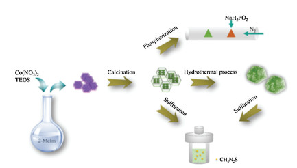
In this paper, we used an easy and economical method to fabricate silica-protection-assisted MOFs. Tetraethoxysilane (TEOS) and Co(NO3)2·6H2O were mixed and rapidly poured into an aqueous solution containing 2-methylimidazole (2-MeIm) and TEOS as the silicon source. A silicon shell was created covering the surface of ZIF-67, resulting in JS. Through pyrolysis, ZIF-67 was transformed into a Co3O4 core and SiO2 copied, retaining the morphology of ZIF-67. Co3O4@SiO2 nanoreactors were obtained through calcining at 350 ℃, 500 ℃, 600 ℃ and 800 ℃. The core shell structure becomes more obvious due to the aggregation of cobalt ions as the calcining temperature increased. A dodecahedron structure with a flaky surface was hydrothermally synthesized, Co3(OH)4Si2O5 was used to fabricate supercapacitor electrodes. Indeed, the SiO2 shells also serve in the calcination process, even hydrothermally, to ensure the orderly growth of nanosheets. This silicon shell protection method can be applied to the synthesis of other MOF-derived nanoreactors, which not only maintain the favorable morphology of MOF but also disperse the metal oxide particles evenly. However, the electrical conductivity of the silicon shell is poor, thus creating the demand for a more stable shell with better electrical conductivity. To develop more nanoreactors, Co3O4@SiO2 and Co3(OH)4Si2O5 with the best morphologies and properties were respectively selected to synthesize CoSx and CoP-SiO2 by sulfuration and phosphorization.
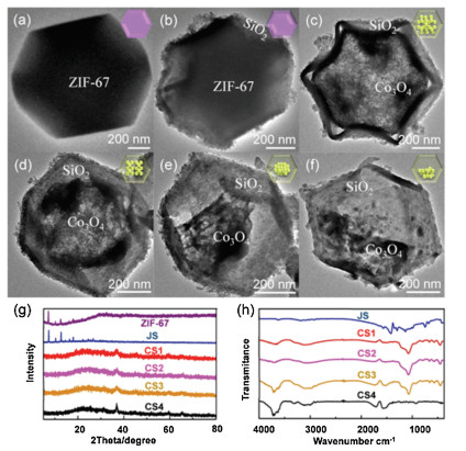
Scheme 1 illustrates the synthetic method for all nanoreactors in this study. The morphological structures and microstructural features of the obtained samples of JS, Co3O4@SiO2, Co3(OH)4Si2O5 and their derivatives were illustrated by SEM and TEM. These SEM images show that the synthesized ZIF-67, JS and Co3O4@SiO2 possess a similar structure, namely, a uniform rhombic dodecahedron. Obviously, the surface of JS (Fig. S1b-b1 in Supporting information) is rougher than that of ZIF-67 (Fig. S1a-a1 in Supporting information), which proves that the coating process is successful. Here, we also examined the specific surface area and porous structure of ZIF-67 by Brunauer-Emmett-Teller (BET) gas sorption measurements. This result illustrated the typical microporous adsorption process, indicating a large Brunauer-EmmettTeller specific surface area (SBET) of 1142.97 m2/g (Fig. S2 in Supporting information). Fig. S3 (Supporting information) displays the TGA curves of JS, N2 isotherm of JS can refer to previous literature [24]. When the calcination temperature is raised from 350 ℃ to 800 ℃, the surface of Co3O4@SiO2 becomes smoother as seen in the enlarged SEM images (Figs. S1c1-f1 in Supporting information). To further investigate this kind of shell-core structure, we used TEM, as illustrated in Fig. 1. The core (Co3O4) is well encased in the silica shell, which indicates that the shell still maintains its original structure without damage through increased calcination time. As the temperature increases, the core reduces in size and can even collapse. This phenomenon demonstrates that SiO2 has excellent stability at high temperatures (600 ℃, 800 ℃), while Co3O4 particles produce severe agglomeration. Energy dispersive X-ray spectroscopy (EDX) elemental mapping demonstrates the presence of Si, Co and O elements in CS1, CS2, CS3, and CS4 (Fig. S4 in Supporting information). As seen from Figs. 1c-f, as the pyrolysis temperature increases, the Co3O4 core decreases and gradually collapses. The TEM images prove that the precursor has a uniform and stable shell core structure, which is very beneficial to the construction of subsequent derivatives. The phase and crystal structures of the as-synthesized samples were analyzed using powder X-ray diffraction (XRD) patterns measurements (Fig. 1g).

|
Download:
|
| Scheme 1. Illustration of the preparation process of the JS, Co3O4@SiO2, Co3(OH)4Si2O5 and derivatives. | |

|
Download:
|
| Fig. 1. TEM images of (a) ZIF-67, (b) JS, (c) CS1, (d) CS2, (e) CS3, and (f) CS4. (g) XRD pattern of ZIF-67, JS, CS1, CS2, CS3, CS4. (h) FTIR spectra of JS, CS1, CS2, CS3, CS4. | |
The XRD patterns are consistent with previous reports [24]. The existence of strong and sharp peaks indicates the good crystallinity of JS and the peak shape of CSH4 is sharper, indicating that the crystallinity is better with the increase of temperature. Furthermore, these curves show that CS1, CS2, CS3 and CS4 are identical substances (Fig. S5 in Supporting information). Subsequently, FT-IR spectra of the JS, CS1, CS2, CS3 and CS4 were analyzed showing that the samples have the same molecular structure apart from obvious differences in JS (Fig. 1h). The compounds show a significant peak approximately 1100 cm-1, which is caused by the anti-symmetric stretching vibration of the Si-O-Si bond. The absorption peak of CS4 at 900 cm-1 is the symmetric stretching vibration absorption peak of the Si-O-Si bond. Meanwhile, several Raman peaks appear between 500 cm-1 and 1000 cm-1, which could be attributed to the existence of the Co3O4 structures (Fig. S7 in Supporting information). The specific chemical compositions and electronic structure of the as-prepared Co3O4@SiO2 was further confirmed through using X-ray photoelectron spectroscopy (XPS). The high-resolution XPS Co 2p spectra are given in Fig. S6 (Supporting information) and four significant peaks of Co 2p can be clearly observed. These peaks represent the characteristic peaks of Co3O4 at Co 2p3/2 and 2p1/2 levels. The peaks between 796 eV and 800 eV are from Co 2p1/2, while the peaks between 775 eV and 786 eV are caused by Co 2p3/2, and the remaining peaks are shakeup satellites (sat.). In addition, the peaks located at 799.32 eV (797.53 eV, 799.44 eV, 799.17 eV) and 784.67 eV (782.65 eV, 783.69 eV, 783.32 eV) are characteristic of Co2+ species, and the peaks at 796.14 eV (795.30 eV, 795.89 eV, 796.05 eV) and 780.92 eV (780.17 eV, 780.74 eV, 780.73 eV) correspond to Co3+. The presence of Co2+ and Co3+ ions in Co3O4@SiO2 was confirmed by the high-resolution Co 2p spectrum, which further demonstrated the successful transformation of elemental cobalt into cobalt oxide.
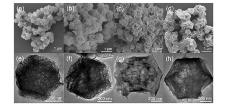
These precursors have a regular and solid structure even after testing, and possess great potential to form a variety of nanoreactors. Compared to other nanostructures, the nanosheet structure has a large specific surface area, which is conducive to charge and mass transport in the electrochemical process [44-46]. Thus, using Co3O4@SiO2 as a template, we exploited a facile hydrothermal method to synthesize a material with a flaky surface, as illustrated in Figs. 2a-d. From TEM images, we can see that the Co3O4 core disappears, and is replaced by nanosheets, and the dodecahedron structure is still preserved (Figs. 2e-h). It can be inferred that the Co3O4 core reacts with the SiO2 shell in an aqueous environment to promote the formation of flaky Co3(OH)4Si2O5. XRD patterns demonstrates the accuracy of the above inference; there are several distinct peaks that approximate the standard peaks. In addition, the variation trend and peak position of these curves are basically identical, indicating that CSH1, CSH2, CSH3 and CSH4 are the same substance with different nanosheet distribution (Fig. S8 in Supporting information). The transformation of Co3O4@SiO2 to Co3(OH)4Si2O5 has been observed by the Co 2p spectrum (Fig. S9 in Supporting information). The strong peaks located at 797.86 eV (797.80 eV, 797.84 eV, 797.32 eV) and 781.59 eV (781.47 eV, 781.71 eV, 780.84 eV) were respectively assigned to the Co 2p1/2 and Co 2p3/2, which proves the presence of Co2+ ions. In addition, sat. signals at high binding energy (approximately 803 eV and 787 eV) are ascribed to multielectron excitation. The results are consistent with the formation of Co3(OH)4Si2O5. The XPS Co 2p spectrum comparison of CS series and CSH series is shown in the Fig. S10 (Supporting information), it is obvious that the peaks position are shifed. For comparison, we also put ZIF-67 and JS into the reactors for 12 h (24 h) at 120 ℃ (180 ℃), and the obtained products are labeled as J1, J2, JS1, and JS2. Figs. S12a and b (Supporting information) show the morphologies of J1, J2 with a disordered distribution, which reflects the covering of SiO2. Meanwhile, JS1 displays a broken and irregular structure while JS2 exhibits the opposite. It can be clearly seen from TEM that JS2 generates nanosheets, but the reaction is incomplete, as attributed to the incomplete transformation of ZIF-67 (Fig. S13b-b1 in Supporting information). These results further validate the importance of the calcining process.

|
Download:
|
| Fig. 2. SEM and TEM images of Co3(OH)4Si2O5 derived from Co3O4@SiO2 at different calcination temperature: (a, e) CSH1, (b, f) CSH2, (c, g) CSH3, (d, h) CSH4. | |
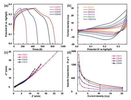
The electrochemical energy storage performance can be significantly boosted by optimizing the microstructure of materials. According to the above description of the structure of Co3(OH)4Si2O5, several properties are applicable for supercapacitor applications.Co3(OH)4Si2O5 overcomes the low conductivity of Co3O4@SiO2 and the nanoreactor controls the growth of flaky cobalt silicate in an ordered structure, which facilitates electron transport. Therefore, the unique morphology of cobalt silicate makes it possible to fully realize its potential in supercapacitor applications. The electrochemical performance of CSH1, CSH2, CSH3 and CSH4 as supercapacitor electrodes was evaluated in a three-electrode system through carrying out cyclic voltammetry (CV) and galvanostatic charge-discharge (GCD) measurements in a 3 mol/L KOH electrolyte solution with a platinum wire as the auxiliary electrode and Hg/HgO as the reference electrode. Fig. 3a compares the GCD curves of the CSH1, CSH2, CSH3, and CSH4 electrodes at a current density of 1 A/g. The CSH2 electrode has the longest charging-discharging time and its specific capacitance is higher than that of the CSH1, CSH3 and CSH4 electrodes. Through calculation based on the GCD curves, the specific capacitance of the CSH2 electrode is approximately 1648 F/g and is higher than other electrodes, especially the CSH1 electrode at 0.5 A/g. It can be clearly seen that the performance of electrodes prepared by CSH series is far better than that of CS series (Fig. S11 in Supporting information). The dispersion of Co3O4 particles in the silica shell is uniform, and spatial distribution between the core and shell of the CSH2 nanoreactor is more appropriate and beneficial for the growth of flaky substances on the surface of dodecahedron. Fig. 3b exhibits the CV curves of the CSH2 electrode at different scan rates ranging from 5 mV/s to 100 mV/s with a similar shape, which suggests exceptional charge storage performance. Over the range of scanning rates, the cycle amplitude of the curves changes slightly, indicating ions transport properties and electrical conductivity of the sample are improved. The capacitance characteristics of the electrode material play an important role in potential high-power applications. The corresponding Nyquist plots are steep in the low frequency region and therefore the resistance of electrolyte ions in these active substances is low (Fig. 3c). The remarkable performance is attributed to a great deal of special structures with high surface areas. This unique structure has a large contact area with the electrolyte and offers space for buff; ering strains, thereby reducing the charge transfer resistance and improving electrochemical performance. Fig. 3d compares the specific capacitance of the CSH1, CSH2, CSH3 and CSH4 electrodes at different current densities. Although the specific capacitance was slightly lower than that of CSH4, as the current density increases the CSH2 exhibits a better rate capability than other three samples at 0.5, 1, 2 A/g. As mentioned, CSH2 combines the advantages of good rate capability and high capacitance, and will serve as a future guidance in the field of electrochemical energy storage.

|
Download:
|
| Fig. 3. (a) Galvanostatic charge-discharge curves of CSH1, CSH2, CSH3, CSH4 at a current density of 1.0 A/g. (b) Cyclic voltammetry curves of CSH2 at different scan rates. (c) Nyquist plots of CSH1, CSH2, CSH3, CSH4. (d) Plots of the current density against specific capacitances of CSH1, CSH2, CSH3, CSH4 obtained from galvanostatic charge/discharge curves. | |
The above precursors are selected as fabricating composites to develop more nanoreactors. The CoSx are synthesized by varying ZIF-67, JS, CS2, CSH2 as cobalt precursors and CH4N2S as sulfur precursors under the hydrothermal condition of 120 ℃ (160 ℃), over 12 h. The morphologies of all products are displayed in Figs. S12c and d, S13c and d, S15a and b and S14a-f (Supporting information). According to these SEM images, we can conclude that only CS2 and CSH2 can provide the precursors required for this complex reaction. EDX elemental mapping was used to verify the success of the sulfur coating reaction and fully demonstrated that Si, Co, S and O elements were present in CSS1 (Fig. S15c in Supporting information). The lattice fringes of CSS1 are not found in HRTEM image and the SAED pattern is shown in Fig. S15d (Supporting information). The SEM and TEM images in Figs. S15e and f (Supporting information) show the morphology of CoP-SiO2 (CP), which is similar to CSH2. The structure of CP is intact during the calcination process due to the exceptional physical and chemical stability of SiO2. We used EDX elemental mapping to further demonstrate successful phosphorization. The chemical reaction between PH3 gas and Co3O4 occurs in the reactor, thus the silica shell is beneficial for diffusion of a gas reactant and it can be seen in the mapping diagram that P element is mainly distributed inside the reactor (Fig. S15g in Supporting information). It is worth noting that no lattice fringes of CP are observed in the HRTEM image, indicating the existence of amorphous SiO2. The SAED mode is displayed on the upper right corner of Fig. S15 h (Supporting information). To further confirm elemental composition of the composites, XPS and XRD analyses are conducted and the results are shown in Figs. S16 and S17 (Supporting information).
In summary, we have introduced an economic and easy approach to synthesize a set of nanoreactors with unique morphologies. The obtained Co3O4@SiO2 dispersed cobalt trioxide particles evenly in a controlled space and effectively limited the aggregation of cobalt ions and leaching of particles. More importantly, this silicon shell protection method can be extended to construct other MOF-derived nanoreactors with different morphologies. The increased surface area of the flaky dodecahedral structure formed byCo3(OH)4Si2O5 and the conversion of the semiconductive properties of precursors are crucial for boosting the performance of these materials. The specific capacitance of CSH2 can reach 1648 F/g at a current density of 0.5 A/g due to its rational structure. CS2 was combined with sulfides and phosphides to fabricate new nanoreactors, and in the future, these materials will be applied in other fields. Although it is still a challenging process to design a nanoreactor with excellent morphology and electrical conductivity, we believe that the synthetic methods in this work are instructive for the future development of the nanoreactors.
AcknowledgmentsThis work was supported by the National Natural Science Foundation of China (NSFC, Nos. 21671170, 21673203), the Topnotch Academic Programs Project of Jiangsu Higher Education Institutions (TAPP), Program for New Century Excellent Talents of the University in China (NCET, No.13-0645), the Six Talent Plan (No. 2015-XCL-030), and Qinglan Project. We also acknowledge the Priority Academic Program Development of Jiangsu Higher Education Institutions and the technical support we received at the Testing Center of Yangzhou University.
Appendix A. Supplementary dataSupplementary material related to this article can be found, in the online version, at doi:https://doi.org/10.1016/j.cclet.2019.08.044.
| [1] |
B. Li, J. Ma, P. Cheng, Angew. Chem. Int. Ed. 57 (2018) 6834-6837. DOI:10.1002/anie.201801588 |
| [2] |
X. Xiao, Q. Li, X. Yuan, et al., Small Methods (2018) 1800240. |
| [3] |
S. Li, F. Huo, Nanoscale 7 (2015) 7482-7501. DOI:10.1039/C5NR00518C |
| [4] |
L. Chen, R. Luque, Y. Li, Chem. Soc. Rev. 46 (2017) 4614-4630. DOI:10.1039/C6CS00537C |
| [5] |
X. Li, S. Zheng, L. Jin, et al., Adv. Energy Mater. 8 (2018) 1800716. DOI:10.1002/aenm.201800716 |
| [6] |
Y. Li, Y. Xu, W. Yang, et al., Small 14 (2018) 1704435. DOI:10.1002/smll.201704435 |
| [7] |
J. Yang, F. Zhang, H. Lu, et al., Angew. Chem. Int. Ed. 54 (2015) 10889-10893. DOI:10.1002/anie.201504242 |
| [8] |
W. Liu, J. Huang, Q. Yang, et al., Angew. Chem. Int. Ed. 56 (2017) 5512-5516. DOI:10.1002/anie.201701604 |
| [9] |
Y. Xu, B. Li, S. Zheng, et al., J. Mater. Chem. A:Mater. Energy Sustain. (2018) 22070-22076. |
| [10] |
D. Saliba, M. Ammar, M. Rammal, M. Al-Ghoul, M. Hmadeh, J. Am. Chem. Soc. 140 (2018) 1812-1823. DOI:10.1021/jacs.7b11589 |
| [11] |
H.B. Wu, B.Y. Guan, P. He, X.Y. Yu, J. Mater. Chem. A:Mater. Energy Sustain. 6 (2018) 19338-19341. DOI:10.1039/C8TA07080F |
| [12] |
J. Peng, X. Sun, Y. Li, et al., Microporous Mesoporous Mater. 268 (2018) 268-275. DOI:10.1016/j.micromeso.2018.04.005 |
| [13] |
S. Zheng, B. Li, Y. Tang, et al., Nanoscale 10 (2018) 13270-13276. DOI:10.1039/C8NR02932F |
| [14] |
C. Jiao, Z. Wang, X. Zhao, et al., Angew. Chem. Int. Ed. 58 (2019) 996-1001. DOI:10.1002/anie.201811683 |
| [15] |
M. Zhong, D. Yang, C. Xie, et al., Small 12 (2016) 5564-5571. DOI:10.1002/smll.201601959 |
| [16] |
W. Yang, X. Li, Y. Li, R. Zhu, H. Pang, Adv. Mater. (2018) 1804740. DOI:10.1002/adma.201804740 |
| [17] |
Y. Li, Y. Fu, W. Liu, Y. Song, L. Wang, J. Alloys. Compd. 784 (2019) 439-446. DOI:10.1016/j.jallcom.2019.01.085 |
| [18] |
G. Li, M. Chen, Y. Ouyang, et al., Appl. Surf. Sci. 469 (2019) 941-950. DOI:10.1016/j.apsusc.2018.11.099 |
| [19] |
J. Zhang, H. Zhao, J. Li, et al., Adv. Energy Mater. 9 (2019) 1803221. DOI:10.1002/aenm.201803221 |
| [20] |
X. He, S.Z. Luan, L. Wang, et al., Mater. Lett. 244 (2019) 78-82. DOI:10.1016/j.matlet.2019.01.144 |
| [21] |
J. Xu, Y. Wang, S. Cao, et al., J. Mater. Chem. A:Mater. Energy Sustain. 6 (2018) 17329-17336. DOI:10.1039/C8TA05976D |
| [22] |
Y. Yan, Y. Luo, J. Ma, et al., Small 14 (2018) 1801815. DOI:10.1002/smll.201801815 |
| [23] |
W.D. Oh, Z. Dong, Z.T. Hu, T.T. Lim, J. Mater. Chem. A:Mater. Energy Sustain. 3 (2015) 22208-22217. DOI:10.1039/C5TA06563A |
| [24] |
M. Zhang, C. Wang, C. Liu, et al., J. Mater. Chem. A:Mater. Energy Sustain. 6 (2018) 11226-11235. DOI:10.1039/C8TA03565B |
| [25] |
Y. Yang, W. Cheng, Y.F. Cheng, Appl. Surf. Sci. 476 (2019) 815-821. DOI:10.1016/j.apsusc.2019.01.157 |
| [26] |
X. Li, J. Wei, Q. Li, et al., Adv. Funct. Mater. 28 (2018) 1800886. DOI:10.1002/adfm.201800886 |
| [27] |
Z. Li, H.C. Zeng, J. Am. Chem. Soc. 136 (2014) 5631-5639. DOI:10.1021/ja409675j |
| [28] |
Q. Yue, J. Li, Y. Zhang, et al., J. Am. Chem. Soc. 139 (2017) 15486-15493. DOI:10.1021/jacs.7b09055 |
| [29] |
X.B. Meng, J.L. Sheng, H.L. Tang, et al., Appl. Catal. B:Environ. 244 (2019) 340-346. DOI:10.1016/j.apcatb.2018.11.018 |
| [30] |
P. Destito, A. Sousa-Castillo, J.R. Couceiro, et al., Chem. Sci. 10 (2019) 2598-2603. DOI:10.1039/C8SC04390F |
| [31] |
K.J. Kim, Y. Zhang, P.B. Kreider, et al., Thin Solid Films 659 (2018) 24-35. DOI:10.1016/j.tsf.2018.05.026 |
| [32] |
C. Galeano, C. Baldizzone, H. Bongard, et al., Adv. Funct. Mater. 24 (2014) 220-232. DOI:10.1002/adfm.201302239 |
| [33] |
Y. Pan, K. Sun, S. Liu, et al., J. Am. Chem. Soc. 140 (2018) 2610-2618. DOI:10.1021/jacs.7b12420 |
| [34] |
W. Zhang, G. Lu, C. Cui, et al., Adv. Mater. 26 (2014) 4056-4060. DOI:10.1002/adma.201400620 |
| [35] |
J. Odrobinska, E. Gumieniczek-Ch łopek, M. Szuwarzynski, et al., ACS Appl. Mater. Interfaces 11 (2019) 10905-10913. DOI:10.1021/acsami.8b22690 |
| [36] |
X. Guo, G. Zhang, Q. Li, H. Xue, H. Pang, Energy Storage Mater. 15 (2018) 171-201. DOI:10.1016/j.ensm.2018.04.002 |
| [37] |
H. Tang, M. Zheng, Q. Hu, et al., J. Mater. Chem. A:Mater. Energy Sustain. 6 (2018) 13999-14024. DOI:10.1039/C8TA03644F |
| [38] |
A. Aijaz, A. Karkamkar, .J Y, et al., J. Am. Chem. Soc. 134 (2012) 13926-13929. DOI:10.1021/ja3043905 |
| [39] |
N.N. Zhu, X.H. Liu, T. Li, et al., Inorg. Chem. 56 (2017) 3414-3420. DOI:10.1021/acs.inorgchem.6b02855 |
| [40] |
G. Lu, S. Li, Z. Guo, et al., Nat. Chem. 4 (2012) 310-316. DOI:10.1038/nchem.1272 |
| [41] |
M. Zhao, K. Yuan, Y. Wang, et al., Nature 539 (2016) 76-80. DOI:10.1038/nature19763 |
| [42] |
W. Wang, Y. Li, R. Zhang, et al., Catal. Commun. 12 (2011) 875-879. DOI:10.1016/j.catcom.2011.02.001 |
| [43] |
G. Huang, D.M. Yin, L.M. Wang, J. Mater. Chem. A:Mater. Energy Sustain. 4 (2016) 15106-15116. DOI:10.1039/C6TA05389K |
| [44] |
Q. Wang, Y. Zhang, H. Jiang, T. Hu, C. Meng, ACS Appl. Energy Mater. 1 (2018) 3396-3409. DOI:10.1021/acsaem.8b00556 |
| [45] |
Y. Yang, Q. Liang, J. Li, et al., Nano Res. 4 (2011) 882-890. DOI:10.1007/s12274-011-0144-7 |
| [46] |
Q. Li, Y. Xu, S. Zheng, et al., Small 14 (2018) 1800426. DOI:10.1002/smll.201800426 |