 2020, Vol. 31


b BaiYin Research Institute of Novel Materials, Lanzhou University of Technology, Lanzhou 730050, China
One of the main reasons for the worsening environmental pollution is the excessive use of non-renewable energy sources such as coal and oil, which further exacerbates the energy crisis. Therefore, people urgently need a green, efficient and safe renewable energy to alleviate this situation. Currently developed energies such as solar energy, wind energy, geothermal energy, etc., have their own advantages, but the common shortcomings are also obvious like they are often limited by time and geography, so these energies cannot be widely used [1-4]. Among various electric energy sources, lithium ion battery has been used as promising candidates due to their high voltage and high energy density. However, the safety problem caused by the side reaction of lithium hexafluorophosphate and organic carbonate under overcharge or high temperature conditions is still a huge challenge [2, 5-7]. As an alternative candidate, aqueous supercapacitors (SCS) have been extensively studied due to their high-power density, excellent cycle stability, superior safety performance, environmentally friendly, and low cost. It is essential to develop advanced SCs for future multi-functional electronic products, and to achieve high energy density. For this reason, improving capacitance of SCs device or increasing the operating voltage would be an effective way to increase its energy density [3, 8, 9]. Electrochemically performance of SCs depends on a large extent on the electrode material. In recent years, conductive polymers and metal oxides have been extensively studied compared to carbon materials with excellent redox kinetics and ultra-high specific capacitance, while conventional carbon-based materials adsorb ions to form a doubleelectrode layers storing energy, which has long-term cycling stability; however, carbon materials are often limited in practical application because of its low energy density [10-12]. Recent studies showed that combination of carbon-based materials and metal oxides/conductive polymers to design attractive nanostructures is effective in expanding the potential window, shortening the ion diffusion path, improving the wettability of materials, and thus improving electrochemical property of materials [13-17].
There are many ways to prepare electrode materials. For example, J. Balamurugan et al. prepared Ni-Mo-S and Ni-Fe-S nanosheets for an all-solid supercapacitor by hydrothermal method. When the power density was 0.561 kW/kg, the energy density was 82.13 kW/kg [18]. H. He et al. prepared a composite of carbon and rod TiO2 by solvothermal method and applied it to a sodium ion battery at 5000 mA/g with a capacitance of up to 153.9 mAh/g [19]. A. Reddy et al. prepared a nitrogen-doped layered graphene material by solvothermal chemical vapor deposition and used it in a lithium ion battery with twice the capacity of a non-nitrogen-containing material [20]. X. Rui et al. prepared a three-dimensional layered Na3V2(PO4)3 in which mesopores and macropores coexisted by using a freeze-drying method and used it in a sodium ion battery, and the capacity retention rate after 10, 000 cycles at 100 ℃ was 64% [21]. Z. Mao et al. used electrospinning to prepare composites of carbon nanofiber coated Co3O4 nanoparticles and used them in sodium ion batteries. The specific capacity at a current density of 500 mA/g was 251.7 mA/g [22]. J. Wei et al. prepared a N-doped ordered mesoporous carbon with a tunable dielectric structure by using a template method as a supercapacitor negative electrode material with a specific capacitance of 227 F/g in 6 mol/L KOH at a current density of 0.2 A/g [23]. Various preparation methods of materials have their own advantages. The electrospinning process has many unique properties in various preparation processes for materials [24-28]. Mainly used for solution spinning, controlling the viscoelasticity and curing rate of the spinning fluid by changing the chemical composition of the solute/solvent and the relative molecular mass of the polymer [29, 30]. This technique can be used for spinning a variety of polymers, including some experimental materials that are too small to be spun by conventional methods. The prepared nanofiber has excellent characteristics such as controllable diameter, large specific surface area and high porosity, which makes it a research focus for developing ultrafine nanofibers [31-35].
In this paper, we prepared a nanofiber material composed of hierarchical porous carbon and nano nickel oxide (HPCF@NiO) by electrospinning, phase separation, and high-temperature carbonization. Specifically, a triblock copolymer of PAA-b-PAN-b-PAA is synthesized by reversible addition-fragmentation chain transfer, which has the same chain of PAN. The blending of PAN and PAA-b-PAN-b-PAA was further used as carbon source for heat-treatment, when metal hydroxide particles of Ni(OH)2 are converted into amorphous oxidation (NiO). By changing the ratio of PAN to PAA-b-PAN-b-PAA, a certain number of macropores and mesopores are presented in composite to ensure rapid transport of electrolyte; while generate many micropores, which facilitates adsorption of ions in electrolysis. The hierarchical interaction of pores optimizes electrochemical performance of the material. According to the test, the mass ratio capacitance at the current density of 1 A/g reached 188.7 F/g. With the activated carbon electrode as the negative electrode, after 12, 500 cycles in 2 mol/L KOH, the capacity retention rate is 85.7%, showing excellent cycle performance. This is mainly due to the advanced structure and the synergy affection between carbon materials and metal oxides.
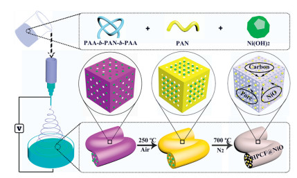
Scheme 1 mainly showes the preparation process of hierarchical porous nanofibers of carbon@nickel oxide nanoparticles (HPCF@NiO). Spinning by means of an electrospinning device was used and the casting solution was composed of an amphiphilic block copolymer (PAA-b-PAN-b-PAA), nickel hydroxide nanoparticle (Ni(OH)2) synthesized by chemical coprecipitation method, a polymer polyacrylonitrile (PAN), and organic small molecule (DMF) as a solvent. The block copolymer prepared by reversible addition-fragmentation chain-transfer polymerization. The same polymer chain of PAN with the bulk made the two had an excellent blend compatibility, which played a good role in the preparation of uniform nanofibers through electrostatic spinning. Next, the spun fibers were allowed to stand in deionized water for 24 h. Phase separation occurred during this process and the block copolymer self-assembled to form a multi-polymer phase system, accompanied by rapid solvent exchange, which greatly promoted the formation of porous structures. Then the phase-converted nanofibers were collected, dried in a vacuum oven, and preoxidized for 1 h at 250 ℃ in an air atmosphere. The main purpose of the pre-oxidation was to pre-crosslink the PAN prior to carbonization, while also allowing a portion of the -PAA chain in the block copolymer to be initially thermally decomposed. Finally, annealing at 700 ℃ for 1 h in a nitrogen atmosphere, and the main role of annealing was to convert the polymer into a carbon substrate at a higher temperature, while promoting the decomposition of a part of the chain in the macromolecular chain, which would generate a large amount of pore. In this process, nickel hydroxide was converted into a more stable non-static nickel oxide (NiO). The production of porous structures was mainly the decomposition of partial chains in macromolecular chains. Therefore, the mass ratio of PAN to PAA-b-PAN-b-PAA was a major factor affecting the number and morphology of the pores, so it was necessary to adjust the ratio of the two to explore the effect on the pores. Based on this, a series of experiments were carried out in which the mass ratios of PAN and PAA-b-PAN-b-PAA were 1.1:0.6, 1.3:0.4, 1.5:0.2, and 1.7:0 (named as CF), and the mass of Ni(OH)2 remained unchanged at 0.1 g. Through electrochemical tests, we found that when the ratio of the two was 1.3:0.4, the electrochemical performance was optimal. As a comparison, the comparative sample without Ni(OH)2 at the ratio was termed as HPCF. Specific experimental details could be added to the experimental section of the Supporting information

|
Download:
|
| Scheme 1. Schematic illustration of the synthesis process for HPCF@NiO. | |
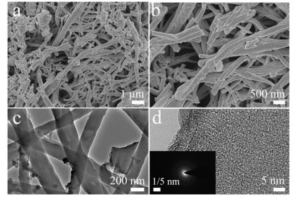
The morphology and microstructure of the experimental samples were characterized by field emission scanning electron microscopy (FESEM) and transmission electron microscopy (TEM). Fig. 1 is an SEM image of HPCF@NiO after carbonization at 800 ℃ after pre-oxidation at 250 ℃. From the low-magnification SEM image (Fig. 1a), it could be seen that the crosslinked nanofibers with longer length and smaller diameter were constructed with closely related network structures, some of which were broken, which might be due to the shrink at high temperature treatment of the block copolymer and the presence of NiO particles inside the fiber caused cracks due to stress concentration during cooling, thereby causing partial fibers breakage. This result could be seen more clearly from high-magnification SEM (Fig. 1b). Fig. S2 (Supporting information) is an SEM image of nanofibers prepared from a casting solution without the PAA-b-PAN-b-PAA and Ni(OH)2. It was found that ellipsoidal particles were present and the surface was smooth, mainly due to poor formability when no block copolymer was added and voltage instability during electrospinning. Figs. S4 and S5 (Supporting information) are SEMs for Ni(OH)2 and HPCF. It can be seen from the low-magnification TEM of Fig. 1c that the prepared fibers had a staggered network distribution and a uniform thickness, and the diameter was about 200 nm. From the high-magnification TEM (Fig. 1d), it was found that white dots were evenly distributed on it, indicating that the fibers exhibited a porous structure, which was consistent with the BET results made herein. The inset was a selected area electron diffraction image of HPCF@NiO. The diffraction ring in the figure was darker, indicating that the material had poor crystallinity, mainly because NiO accounts for a small proportion and existed in an amorphous state. In order to verify the successful preparation of the experimental sample, it could be analyzed by means of Fourier transform infrared spectrometer (FTIR), proton nuclear magnetic resonance spectra (1H NMR spectra), X-ray diffraction (XRD) and energy dispersive X-ray spectroscopy (EDS). Characterization of macro-RAFT agent of PAA and PAA-b-PAN-b-PAA by FTIR and 1H NMR spectra, specific detail analysis could be found in Fig. S1 (Supporting information). It was indicated by XRD and EDS that HPCF@NiO had been successfully prepared and the details could be seen in Fig. S3 (Supporting information).

|
Download:
|
| Fig. 1. (a, b) SEM and (c, d) TEM images of HPCF@NiO (inset is the selected-area electron diffraction pattern). | |
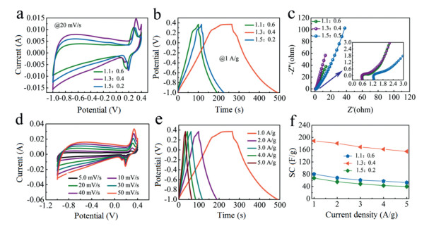
The CF, CF@NiO, HPCF, and C@NiO were electrochemically tested by cyclic voltammetry (CV), galvanostatic charging-discharging (GCD) and electrochemical impedance spectroscopy (EIS). Specific information could be seen in Fig. S6 (Supporting information). In order to investigate the effect of the amount of polymer (PAN) and block copolymer (PAA-b-PAN-b-PAA) added on the electrochemical performance of HPCF@NiO. We took the mass ratios of PAN and PAA-b-PAN-b-PAA respectively: 1.1:0.6, 1.3:0.4 and 1.5:0.2. For the controllabilityof the experimental variables, the amount of Ni(OH)2 added in the casting solution was 0.1 g. Fig. 2 shows the electrochemical test results of the three electrode materials. Fig. 2a is a comparison of their CV curves at 20 mV/s. It was observed that as the amount of addition of PAN increased, that was, the amount of addition of PAA-b-PAN-b-PAA gradually decreaseed, the area enclosed by the CV curve first increased and then decreased, with 1.3:0.4 being the largest. They all had obvious redox peaks, and the peak intensities were similar, which was related to the addition of an equal amount of Ni(OH)2 in the casting solution, which also indicated that some of the capacity was provided by Faradaic pseudocapacitance. The curve in the range of -1~0 V exhibitd a shape similar to a rectangle, mainly because the base material was a carbon material. Fig. 2b is a GCD curve of the three electrode materials at a current density of 1 A/g. It showed that there were discharge platforms at high voltage range, which were consistent with the results of the CV curves. By calculating the mass ratio capacitances of 1.1:0.6, 1.3:0.4 and 1.5:0.2 at this current density were 80.36, 188.7, 63.37 F/g, respectively. Fig. 2c shows their electrochemical impedance spectroscopy curves. From the simulation calculations, the Rs and Rct values of 1.1:0.6, 1.3:0.4 and 1.5:0.2 were 0.959, 0.17 Ω; 0.575, 0.042 Ω; 1.256 and 0.122 Ω. Figs. 2d and e were CV and GCD curves for the best samples at different scan rates and current densities. It showed that the shape of the curves did not undergo significant deformation, whether at a large scan rate and a large current density, indicating that it had excellent rate capability. Fig. 2f shows the mass ratio capacitance of the three at different current densities (1-5 A/g). The specific capacitances at 1 A/g and 5 A/g were 80.36, 52.7 F/g; 188.7, 154.5 F/g and 67.37, 39.78 F/g; respectively. The rate retention were 65.6%, 81.9% and 59%, respectively. The structure of the material affects its electrochemical performance, and we have detailed analysis of its specific effects by means of Nitrogen adsorption-desorption measurements. The specific analysis is in Fig. S7 (Supporting information).

|
Download:
|
| Fig. 2. The electrochemical capacitance performance of HPCF@NiO mediated by various amounts of PAN and triblock copolymer: (a) CV curves at 20 mV/s; (b) GCD curves at 1.0 A/g; (c) Electrochemical impedance spectroscopy curve; (d) specific capacitance at different current densities of 1.0, 2.0, 3.0, 4.0 and 5.0 A/g, respectively. | |
To further evaluate the electrochemical performance of HPCF@NiO as a supercapacitor electrode material. A symmetric supercapacitor was constructed using 2 mol/L KOH as the electrolyte and HPCF@NiO as the electrode material. CV curves of the HPCF@NiO||HPCF@NiO were recorded within a potential range from 0 to 1.4 V at different scanning rates from 5 mV/s to 50 mV/s and presented in Fig. 3a. When the scan rate increased from 5 mV/s to 50 mV/s, the shape of the CV curve was still preserved, demonstrating ultrafast charging-discharging behavior with superior reversibility of HPCF@NiO||HPCF@NiO [36]. The GCD curves of the device with different current densities from 1 A/g to 5 A/g are shown in Fig. 3b. All GCD curves displayed a symmetric nature, demonstrating that HPCF@NiO||HPCF@NiO possessed good electrochemical reversibility and high coulombic efficiency, which was fully consistent with the CV studied. Meanwhile when current density of the device increased from 1 A/g to 5 A/g, the GCD curves showed a negligible IR drop, which signified fast current-voltage response and ultralow resistance [37]. By calculating, the capacities were 21.2 and 15.7 F/g at 1 and 5 A/g, respectively, and the capacitance retention was 74%. Fig. 3c is the EIS of HPCF@NiO|| HPCF@NiO. Through simulation calculation, Rs and Rct were 1.38 and 0.32 Ω, respectively. The reason for the lower impedance of the device was related to the constructed porous carbon-based material. The large pores facilitated the rapid transfer of the electrolyte, and the mesopores and micropores could promote the adsorption of ions. It also showed that this material had good wettability with the electrolyte. Ragone plot (energy density vs power density) of the device is presented in Fig. 3d. The deliver had an excellent energy density of ~ 4.27 Wh/kg at the power density of ~ 3493.6 W/kg. Finally, the cycle test was carried out on HPCF@NiO||HPCF@NiO, and the cycle was repeated 1000 cycles in the current density of 1, 2, 3, 4, 5 and 10 A, and then the previous step was repeated under the same conditions. Finally, it was cycled 500 cycles at 1 A/g. After a total of 12, 500 cycles, the capacity was 85.7% of the initial capacity. This indicated that the structure remained stable after multiple cycles. In summary, the composite material with porous structure prepared by pre-oxidation and carbonized polymer (PAN), block copolymers (PAA-b-PAN-b-PAA) and Ni(OH)2 not only had excellent electrochemical performance, but also had innovative experimental design ideas.

|
Download:
|
| Fig. 3. The electrochemical capacitance performance of HPCF@NiO||HPCF@NiO device: (a) CV curves at various scanning rates; (b) GCD curves at various current densities; (c) Electrochemical impedance spectroscopy curve; (d) Ragone plots; (e) Cycle life at different current density. | |
In summary, a polymer/block copolymer and a metal hydroxide bending system were used as precursor, combined with electrospinning, phase separation, and high-temperature carbonization to prepare a composite of carbon fiber and nickel oxide nanoparticles. The material had a hierarchical porous structure, which was beneficial for supercapacitor material. By characterization, some macropores, mesopores, and abundant micropores coexisted, and the capacitance at a current density of 1 A/g in 2 mol/L KOH was 188.7 F/g. The asymmetric device assembled with activated carbon had a power density of 3497 W/kg at an energy density of 4.27 Wh/kg. After 12, 500 cycles, the capacitance retention was 85.7%. These results indicated that HPCF@NiO was a promising material for high performance supercapacitors.
Declaration of competing interestThe authors declare that they have no known competing financial interests or personal relationships that could have appeared to influence the work reported in this paper.
AcknowledgmentsThis work was partly supported by the National Natural Science Foundation of China (No. 51763014), the Program for Hongliu Distinguished Young Scholars in Lanzhou University of Technology (No. J201801), and Joint fund between Shenyang National Laboratory for Materials Science and State Key Laboratory of Advanced Processing and Recycling of Nonferrous Metals (No. 18LHPY002).
Appendix A. Supplementary dataSupplementary material related to this article canbefound, in the online version, at doi:https://doi.org/10.1016/j.cclet.2019.10.017
| [1] |
F.Y. Cheng, J. Liang, Z.L. Tao, J. Chen, Adv. Mater. 23 (2011) 1695-1715. DOI:10.1002/adma.201003587 |
| [2] |
M.S. Islam, C.A.J. Fisher, Chem. Soc. Rev. 43 (2014) 185-204. |
| [3] |
N.S. Choi, Z.H. Chen, S.A. Freunberger, et al., Angew. Chem. Int. Ed. 51 (2012) 9994-10024. DOI:10.1002/anie.201201429 |
| [4] |
X.H. Xia, D.L. Chao, Y.Q. Zhang, et al., Small 12 (2016) 3048-3058. DOI:10.1002/smll.201600633 |
| [5] |
H.J. Zhang, Y.K. Wang, L.B. Kong, Nanoscale 11 (2019) 7263-7276. DOI:10.1039/C9NR00164F |
| [6] |
Y.G. Wang, Y.F. Song, Y.Y. Xia, Chem. Soc. Rev. 45 (2016) 5925-5950. DOI:10.1039/C5CS00580A |
| [7] |
M.R. Lukatskaya, B. Dunn, Y. Gogotsi, Nat. Commun. 7 (2016) 12647. DOI:10.1038/ncomms12647 |
| [8] |
Y.H. Zhao, H.X. Dong, X.Y. He, et al., ChemElectroChem (2019) 0743. |
| [9] |
Y.M. Ko, M.S. Kwon, W.K. Bae, et al., Nat. Commun. 8 (2017) 536. DOI:10.1038/s41467-017-00550-3 |
| [10] |
Q. Lv, S. Wang, H. Sun, et al., Nano Lett. 16 (2016) 40-47. DOI:10.1021/acs.nanolett.5b02489 |
| [11] |
W.H. Zuo, C.Y. Xie, P. Xu, Y.Y. Li, J.P. Liu, Adv. Mater. 29 (2017) 3463. |
| [12] |
G. Wu, P.F. Tan, X.J. Wu, et al., Adv. Funct. Mater. 27 (2017) 2493. |
| [13] |
F. Ran, Y.T. Tan, W.J. Dong, et al., Polym. Adv. Technol. 29 (2018) 1697-1705. DOI:10.1002/pat.4273 |
| [14] |
Y.T. Tan, Y. Liu, L.B. Kong, L. Kang, F. Ran, J. Power Sources 363 (2017) 1-8. DOI:10.1016/j.jpowsour.2017.07.054 |
| [15] |
M.J. Zhi, C.C. Xiang, J.T. Li, M. Li, N.Q. Wu, Nanoscale 5 (2013) 72-88. DOI:10.1039/C2NR32040A |
| [16] |
A.M. Zardkhoshoui, S.S.H. Davarani, J. Colloid Interface Sci. 535 (2019) 195-204. DOI:10.1016/j.jcis.2018.09.100 |
| [17] |
A. Majeed, P.X. Hou, S. Jiang, et al., J. Mater. Chem. A:Mater. Energy Sustain. 5 (2017) 24813-24819. DOI:10.1039/C7TA08852C |
| [18] |
J. Balamurugan, C. Li, V. Aravindan, N.H. Kim, J.H. Lee, Adv. Funct. Mater. 28 (2018) 3287. |
| [19] |
H. He, Q.M. Gan, H.Y. Wang, et al., Nano Energy 44 (2018) 217-227. DOI:10.1016/j.nanoen.2017.11.077 |
| [20] |
A.L.M. Reddy, A. Srivastava, S.R. Gowda, et al., ACS Nano 4 (2010) 6337-6342. DOI:10.1021/nn101926g |
| [21] |
X.H. Rui, W.P. Sun, C. Wu, Y. Yu, Q.Y. Yan, Adv. Mater 27 (2015) 6670-6676. DOI:10.1002/adma.201502864 |
| [22] |
Z.W. Mao, M. Zhou, K.L. Wang, et al., RSC Adv. 7 (2017) 23122-23126. DOI:10.1039/C7RA02965A |
| [23] |
J. Wei, D.D. Zhou, Z.K. Sun, et al., Adv. Funct. Mater. 23 (2013) 2322-2328. DOI:10.1002/adfm.201202764 |
| [24] |
A. Greiner, J. Wendorff, Angew. Chem. Int. Ed. 46 (2007) 5670-5703. DOI:10.1002/anie.200604646 |
| [25] |
N. Bhardwaj, S.C. Kundu, Biotechnol. Adv. 28 (2010) 325-347. DOI:10.1016/j.biotechadv.2010.01.004 |
| [26] |
T.M. Robinson, D.W. Hutmacher, P.D. Dalton, Adv. Funct. Mater. (2019) 1904664. |
| [27] |
H. Yoshimoto, Y.M. Shin, H. Terai, J.P. Vacanti, Biomaterials 24 (2003) 2077-2082. DOI:10.1016/S0142-9612(02)00635-X |
| [28] |
C.K.S. Pillai, W. Paul, C.P. Sharma, Prog. Polym. Sci. 34 (2009) 641-678. DOI:10.1016/j.progpolymsci.2009.04.001 |
| [29] |
F. Ran, Y.G. Wu, M.H. Jiang, et al., Dalton Trans. 47 (2018) 4128-4138. DOI:10.1039/C7DT04432A |
| [30] |
W.J. Dong, Z. Wang, Q. Zhang, et al., J. Power Sources 419 (2019) 137-147. |
| [31] |
D.G. Yu, J.J. Li, G.R. Williams, M. Zhao, J. Control. Release 292 (2018) 91-110. DOI:10.1016/j.jconrel.2018.08.016 |
| [32] |
A. Haider, S. Haider, I.K. Kang, Arabian J. Chem. 11 (2018) 1165-1188. DOI:10.1016/j.arabjc.2015.11.015 |
| [33] |
Y.Q. Guo, G.J. Xu, X.T. Yang, et al., J. Mater. Chem. 6 (2018) 3004-3015. |
| [34] |
L.F. Chen, Y. Lu, L. Yu, X.W. Lou, Energy Environ. Sci. 10 (2017) 1777-1783. DOI:10.1039/C7EE00488E |
| [35] |
C.R. Wang, S.X. Sun, L.X. Zhang, et al., Colloids Surf. A:Physicochem. Eng. Asp. 561 (2019) 283-291. DOI:10.1016/j.colsurfa.2018.11.002 |
| [36] |
Z.S. Lv, Y.F. Luo, Y.X. Tang, et al., Adv. Mater. 30 (2018) 1704531. DOI:10.1002/adma.201704531 |
| [37] |
H.G. Wang, Z.H. Cheng, Y.Z. Liao, et al., Chem. Mater. 29 (2017) 4885-4893. DOI:10.1021/acs.chemmater.7b00857 |