 2020, Vol. 31


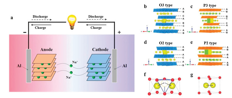
So far, lithium ion batteries have occupied the majority global rechargeable battery market owning to the high energy density, high output voltage and low self-discharging [1, 2]. However, as lithium demand increasing, the sustainable of lithium resources shows up as a concern and the price of lithium is rising fast. Hence, searching a substitute for lithium has become a crucial job of exploring sustainable secondary batteries as well as green energy utilization [3-9]. Na and Li have similar physicochemical properties as Na is right under Li in the periodic table. Na resources are of rich reserves (the fourth richest metal element in the earth's crust) and Na is compatible with the negative aluminum current collectors. In addition, sodium ion batteries and lithium ion batteries work quite in the same way (Fig. 1a): The voltage is generated between the two electrodes (cathode and anode), metal ions (Na+) move forth and back between the two electrodes during charging and discharging, so it is also called a "rocking-chair" battery [10, 11]. In spite of this, in the sodiation and desodiation process, because the size of Na+ is larger than Li+, the electrode materials, especially cathodes materials, suffer from irreversible structural changes. Therefore, it is still a great challenge to develop cathodes with excellent electrochemical properties.

|
Download:
|
| Fig. 1. (a) The working principle of a Na-ion battery system. The classification of transition meta layered oxides (NaxTMO2) crystal structures schematic the for (b) O3-type, (c) P3-type, (d) O2-type and (e) P2-type stacking. The Na+ migration pathways in the O-and P-type frameworks for (f) the indirect Na+ migration pathways with the tetrahedral site gap in O-type frameworks and (g) the direct Na+ migration pathways in P-type frameworks. Reproduced with permission [11]. Copyright 2016, the Royal Society of Chemistry. | |
Up to now, a variety of cathodes for sodium ion batteries have been proposed, such as layered transition metal oxides, polyanionic compounds, Prussian blue compounds and organic compounds [12-20]. Sodium-containing transition metal layered oxides are a very important class among them, which can be presented by NaxTMO2 (0 < x ≤ 1, TM = Mn, Fe, Co, Cr, V and corresponding compound of them). The layered structure is composed of MO6 octahedrons with shared edges, in which Na+ are located between MO6 sheets. Delmas first named it by describing the different chemical environment of Na+ between layers. O indicates Na+ are located in octahedral coordination environment, P indicates Na+ are located in trigonal prism coordination environment. The number of 3 or 2 describes the number of transition metal layers in the repeated stacking unit. NaxTMO2 mainly contains four types O3, P3, O2, P2 (Figs. 1b-e) [21]. When Na+ located in the octahedral sites in O type materials, Na+ need to enter the tetrahedral site gap temporarily and then enter the adjacent octahedral site during migration (Fig. 1f) [22]. P type materials have an open diffusion channel. During migration, Na+ only need to pass through the rectangular surface and directly enter the adjacent trigonal prismatic site (Fig. 1g) [23].
In the past few years, single phase layered cathodes have been studied widely [24-32]. Single phases always maintain their inherent advantages and disadvantages. For example, although O3 phases have a high content of sodium, phase transitions are easy to occur, causing the low kinetics [33-35]. P2 phases possess stable structure and fast Na+ migration, but the sodium content is insufficient, restricting the utilization in full batteries [36-38]. Under this situation, exploiting novel multiphase cathodes which have synergetic effect is an effective way. Multiphase cathodes combine the advantages of different single-phase cathodes and overcome their disadvantages. In this review, we focus on the recent progress about multiphase transition metal layered oxide cathode materials and prospect the future research direction.
2. Single-phase materialsLayered oxide materials for sodium-ion battery cathodes have been widely researched, especially transition metal layered oxides. Mostly due to the facile preparation and high theoretical capacity. Among them, P2 and O3 phases are most reported, and the P3 phase is investigated as well.
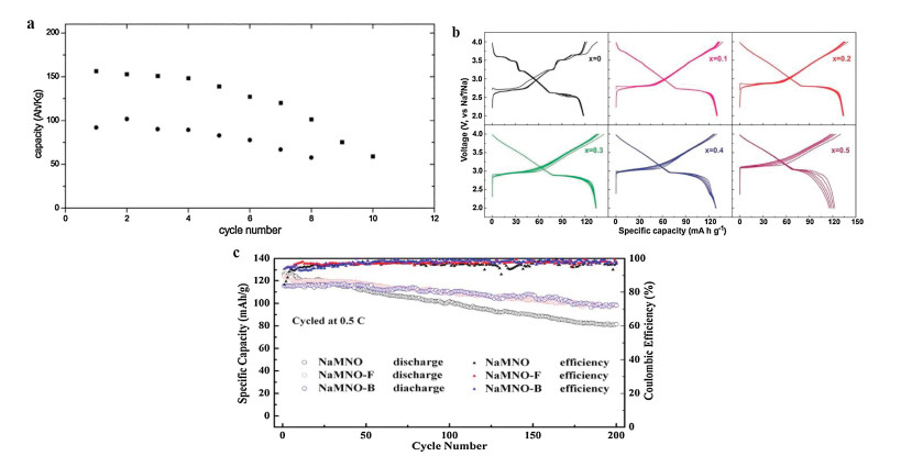
2.1. P2-type materialsAs the nomenclature proposed by Delmas et al., P is on behalf of the Na+ in the prismatic site. In P phases, Na+ share faces with the neighbor sites, so they can directly diffuse into the adjacent site through a rectangular face which brings better rate performance. The capacities of P2 phases are usually high, like Na0.6MnO2 cathode delivers around 150 mA h/g for the first discharge at 2.0-3.8 V, yet the capacity fades quickly after the first few cycles as shown in Fig. 2a [29]. Even narrowing the voltage range to 2.0-3.0 V cannot help. Except for Na0.6MnO2, P2-Na2/3[Fe1/2Mn1/2]O2 cathode also delivers a high capacity of 190 mA h/g [32]. Compared to O3-Na[Fe1/2Mn1/2]O2 which only delivers 100-110 mA h/g, P2 phase performs better in capacity aspect. However, the cyclability of P2-Na2/3[Fe1/2Mn1/2]O2 material is also not good.

|
Download:
|
| Fig. 2. (a) Cycling performance of Na0.6MnO2 for different voltage range; voltage range: (■) 3.8-2.0 V; (●) 3.0-2.0 V. Reproduced with permission [29]. Copyright 2002, the Royal Society of Chemistry. (b) Galvanostatic charge and discharge voltage curves of O3-NaNi0.5Mn0.5-xTixO2 cathodes with different x value (x = 0, 0.1, 0.2, 0.3, 0.4 and 0.5) at 0.05 C (1C = 240 mA/g) between 2.0 V and 4.0 V. Reproduced with permission [33]. Copyright 2017, the Wiley-VCH. (c) Cycling performance of P3-type materials at 0.5C. Reproduced with permission [49]. Copyright 2018, Elsevier. | |
Besides, when P2 phase charged above 4.2 V, for most P2 phase materials, phase transformation takes place that brings about structural change problems [28, 36, 39, 40]. In that case, structure collapses easily and the capacity fades fast. Elements substitution is used to solve this problem by inhibiting the phase transformation. For example, Li-substituted P2-Na0.8Li0.12Ni0.22Mn0.66O2 can suppress the P2-O2 phase transition even at ≈ 4.2 V [28], and P2-Na0.67Ni0.2Mg0.1Mn0.7O2 changed the irreversible P2-O2 to reversible P2-OP4 phase transition [41].
2.2. O3-type materialsThere is another problem with P-type phase that P-type phases are deficient with sodium content, so the first charge capacity is low and first Coulombic efficiency is far from 100%, which arises troubles when building full cells. O3 phases are free from those troubles. O3 phase is a sodium-ion reservoir [42], but since sodium ion has been located in octahedral site, it must diffuse into the tetrahedral interval first then into the adjacent octahedral site. That needs to overcome a larger energy barrier than P2 phases. Many reports on binary or multivariant O3 phases have been reported with high capacity. O3-Na[Li0.05Mn0.50Ni0.30Cu0.10Mg0.05] O2 is synthesized and exhibits a reversible capacity of 172 mA h/g [43]. Most O3 phases suffer from phase transition problems. Guo's group design a series of Ti-substituted NaNi0.5Mn0.5-xTixO2 cathodes [33]. When x = 0, the charge/discharge curve of NaNi0.5Mn0.5O2 material involves a few voltage plateaus and steps, indicating multiple phase transformations. When x > 0 the curves become smoother (Fig. 2b), but the capacities of around 120 mA h/g are still ideal enough. In addition, the majority of O3 phases are air and moisture sensitive.
2.3. P3-type materialsBesides P2 and O3 type materials, P3-type materials have been researched as well. P3 phase has the same direct diffusion pathway as P2 phase. Not like P2 and O3 type materials, the P3 type materials performances are not as well as the others, and it is often investigated in anionic redox or Li+ intercalation [44-47]. Electrochemical performances of P3-NaxNi0.5Mn0.5O2 (x = 0.50, 0.67) was reported [48]. When the voltage window is 2.0-4.5 V, both materials express high capacities about 170 mA h/g, but the cyclicity is awful. After narrowing the voltage window to 2.0-4.0 V, the capacity retention was improved at an expense of capacity. Although the cyclicity is not ideal, the rate performance is great due to the direct diffusion characteristic of P3 phase. Recently, Wang et al. have reported a non-metallic elements doped P3-type Na0.65Mn0.75Ni0.25O2 and Na0.65Mn0.75Ni0.25F0.1O1.9 cathode materials [49]. The F doped material suppresses the P3-O1 phase transition and delivers a higher capacity of 163.7 mA h/g, but the cyclicity for both materials is poor, as shown in Fig. 2c. In general, the performances of P3-type cathode are not optimal, but we can still utilize the advantage of its excellent rate performance in biphase or multiphase materials.
Single phase materials have their unique advantages and disadvantages, if we apply them to form a multiphase material, through the synergetic effect, the advantages may be magnified, and the disadvantages may be neutralized. The new multiphase material may reveal excellent properties.
3. Biphase materialsNow that single phase materials have their inherent advantages and disadvantages, it is natural to consider combining them together to gain advantages and overcome disadvantages. It is also found that some synergetic effects have been produced when combine different phases together.
3.1. P2/O3 biphaseP2 phase and O3 phase have their advantages respectively. It is natural to combine the two phases together to take advantage of synergetic effect. High performance cathode materials with biphasic P2 and O3 phases have been reported recently.
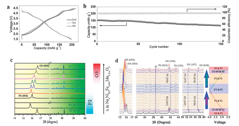
Guo et al. introduced O3 phase into lithium-substituted P2-majority phase forming a P2 + O3 layered oxide composite Na0.66Li0.18Mn0.71Ni0.21Co0.08O2+δ which appears excellent performance [22]. When cycled between 1.5-4.5 V, it delivers a high capacity of 200 mA h/g as well as a good capacity retention of 84% for 50 cycles at 0.2 C and 75% for 150 cycles at a 0.5 C as shown in Figs. 3a and b. It is notable that with the average operating voltage of 3.2 V, the cell reaches 640 Wh/kg for energy density. The c axis of the biphasic material is larger than the pure P2 phase that is beneficial to Na+ diffusion.

|
Download:
|
| Fig. 3. (a) Galvanostatic charge and discharge voltage curves of the P2 + O3 composite Na0.66Li0.18Mn0.71Ni0.21Co0.08O2+δ in the voltage window of 1.5-4.5 V at 0.1 C (1C = 100 mA/g). Reproduced with permission [22]. Copyright 2015, Wiley-VCH. (b) The cycling performance and Coulombic efficiency of the P2 + O3 composite Na0.66Li0.18Mn0.71Ni0.21Co0.08O2+δ at 0.5 C rate. Reproduced with permission [22]. Copyright 2015, Wiley-VCH. (c) XRD patterns of Nax[Ni0.2Fex-0.4Mn1.2-x]O2 with different Na content (0.7 ≤ x ≤ 1.0), and the phase evolution for different Na contents is shown in the right side. Reproduced with permission [52]. Copyright 2017, American Chemical Society. (d) In situ XRD patterns of the Na0.78[Ni0.2Fe0.38Mn0.42]O2 (x = 0.78) cathode obtained during the first charge/discharge at 0.1 C rate in the voltage window of 2.5-4.0 V. Reproduced with permission [52]. Copyright 2017, American Chemical Society. | |
A P2/O3 biphase composite Na0.67Mn0.55Ni0.25Ti0.2-xLixO2 material was synthesized by Li substitution for Ti [50]. Li element mainly enters the TM site to keep the P2 phase, and a small amount of Li enters Na sites to form O3 phase. Li substitution generate some defects to hold charge balance, improve electronic conductivity and diffusion coefficient. As a result, the rate performance, cycling stability are all improved. Meanwhile, the average work voltage is lifted. So, considering the Li substitution as a modifying method is a new way to study novel sodium ion battery cathodes.
Xu et al. reported a P2/O3 material with a triphasic P2/O3/O1 material, we will discuss later[51].Qi and coworkers use the low cost Mn and Fe elements prepared a series of Nax[Ni0.2Fex-0.4Mn1.2-x]O2 materials by a traditional solid state reaction [52]. The X-ray diffraction (XRD) pattern with different x value is displayed in the Fig. 3c. In this case, it can be observed that when sodium content x is higher than 0.8, O3 structure tends to form, and when x < 0.8, O3/P2 composite appears.The capacity and retention vary with the x value. In addition, the full cell with the x = 0.78 cathode still delivers a reversible capacity of 86 mA h/g with a relatively high energy density.From the in situ XRD pattern(Fig. 3d), we can see the P2 phase only experience a solid-solution process, but the O3 phase suffers from a phase transition. But the pattern recovers in the end, manifesting the structure transformation is fully reversible, which illustrates the excellent capacity retention.
P2/O3-Na2/3Li0.18Mn0.8Fe0.2O2 material was also been produced [53].As the author emphasized, this material shows a higher capacity of 125mA h/g than the single P2-phase Na0.85Li0.17Mn0.64Ni0.21O2 reported by Kim et al. [54]. Changes of the parameters of the O3 phase is not detected via ex situ XRD, suggesting the O3 phase is not active. In addition, no OP4 phase is discovered in the charged condition, so the O3 phase may inhibit the gliding of the main phase.
Later, P2/O3-Na0.5(Li0.10Fe0.45Mn0.45)O2 with the same element composition but different stoichiometric ratio was reported as well [55]. In fact, the biphase material is synthesized by doping Li into pristine pure P2 phase Na0.5(Fe0.5Mn0.5)O2 material. When Li content is more than 0.1, the O3 phase becomes the main phase instead of P2. The author tried different Li contents including 0, 0.05, 0.1, 0.2. Among them, the composition of Na0.5(Li0.10Fe0.45Mn0.45)O2 with O3 dominant phase achieves the best performance. It delivers 146.2 mAh/g for the first discharge, the rate capability and capacity retention are promoted too.
The electrochemical performances of P2/O3 biphase materials have been improved compared with either pure P2 phase or pure O3 phase. There are two possibilities, the P2 and O3 phase in the mixed material works together to provide capacity and the advantages of different phases are magnified, or the O3 phase in the biphase material remains inactive that stabilized the lattice.
3.2. P2/P3 biphaseCathodes materials with P2 and P3 phases that both have an open diffusion pathway have also been synthesized.
Na0.45Ni0.22Co0.11Mn0.66O2 material was produced by a solidstate reaction [56]. When the temperature of the final step is 800 ℃, the material is pure P2 phase. But when it comes to 750 ℃, a mixture of the same P2 phase and P3 phase is synthesized. Overall, the biphasic material performs well in both capacity and reversibility than the pure P2 phase material. When changing the electrolyte from organic carbonate to ionic liquid-based that leading to a better performance, the biphasic material delivers over 200 mA h/g.
Later the same group reported NaxNi0.22Co0.11Mn0.66O2 material, which used the same solid-state reaction way [57]. When the sintered temperature is 750 ℃, a biphasic material with P2 and P3 phases was synthesized. The discharge capacity of the 1st cycle is 146.8 mA h/g, the capacity retention from 1st to 200th cycle is 56.7%.
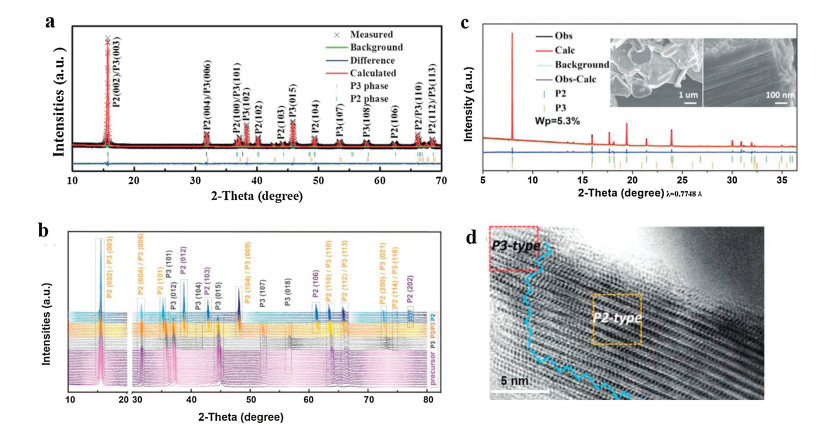
In addition, Zhou et al. presented Na0.66Co0.5Mn0.5O2 material that is a mixture of major P3 and P2 phases (P3: 76.05%, P2: 23.95%) [58]. The calculated XRD patterns are shown in Fig. 4a. It delivers the capacity of 156.1 mA h/g at 1 C. Its electrochemical performance is better than the pure P3-phase Na0.66Co0.5Mn0.5O2. According to the ex situ XRD, phase transition is not observed. And the electrochemical impedance spectroscopy (EIS) result shows that the biphase material displays much smaller Rct (the charge-transfer resistance corresponds to the semicircle diameter in the high-frequency region) values than the pure P3 phase, which indicates easier (de)intercalation for Na+.

|
Download:
|
| Fig. 4. (a) Rietveld refinement XRD pattern of the Na0.66Co0.5Mn0.5O2. The black (red) line represents the experimental (calculated) data, the green and orange bars represent Bragg positions and difference curve is the blue line. Reproduced with permission [58]. Copyright 2015, the Royal Society of Chemistry. (b) XRD patterns for the obtained precursor and calcined materials in different temperatures. Reproduced with permission [60]. Copyright 2018, Elsevier. (c) XRD pattern of Na0.78Cu0.27Zn0.06Mn0.67O2. The inset shows different magnification SEM images. Reproduced with permission [61]. Copyright 2019, Wiley-VCH. (d) ABF image of the P2/P3-Na0.78Cu0.27Zn0.06Mn0.67O2 composite; the red rectangle represents P3-type zone and the orange rectangle represents P2-type zone. Reproduced with permission [61]. Copyright 2019, Wiley-VCH. | |
More recently, Na0.62Mn0.66Ni0.17Co0.17O2 with P3/P2 composite material has been synthesized [59]. The sintered temperature is a little higher than the pure P3 phase, and the c axil became larger. The integration of P3/P2 phases enhance the capacity and cycling stability of the P3 phase, and when there is a substitution of Li, a third phase O'3 appears. The new triphase material performs even better than the P3/P2 integration material, we will introduce later.
Latterly, Na0.7Li0.06Mg0.06Ni0.22Mn0.67O2 material with 46.7% P2 and 53.3% P3 phase was reported [60]. Pure P2 phase prefers to form in higher temperature and P3 phase prefers to form in lower temperature, the XRD structures for the prepared precursor and calcined materials in different temperatures is shown in Fig. 4b. The biphase material was synthesized using an intermediate temperature between pure P2 and P3 to gain both P2 and P3 phase. The biphase structure can be verified by XRD, high resolution transmission electron microscopy and selected area electron diffraction. The cathode delivers a reversible capacity of 119 mA h/g, good capacity retention that maintains 97.2% after 50 cycles and good rate performance. The cathode works in full battery as well. According to the in situ XRD result, during charging and discharging, the material experiences a process from P2/P3 phase to P2/P3/OP4 phase and then change back. The intermediate OP4 phase reducing the structure stress compared with direct P2/P3-O2/P"3 transformation.
Yan et al. designed a low-cost hydrostable biphase material Na0.78Cu0.27Zn0.06Mn0.67O2. Zn substitution induced the intergrowth of P2 and P3 phases that verified by refined XRD pattern (Fig. 4c) [61]. The P3 phase distributes on the surface, and the P2 phase is in the inner side, the phase boundary can be seen clearly on the TEM image (Fig. 4d). The valance variation of Cu and Mn is different. Cu redox participates in both P2 and P3 phases, while Mn redox only happens in P2 phase. The biphase material performs better than the undoped pure P2 material in rate performance and cycling stability. It even maintains the structure and electrochemical performance after soaked in water. In situ synchrotron XRD measurements imply that when charged to 3.8 V, a new phase forms at the expense of P2 phase. The new phase is different from OP4 or Z phase, so called it P2(new) phase. This suggests that the highly disordered phase formation at high voltage is inhibited. Moreover, the interface of the biphase is still clear after first charge and discharge process as the ABF-STEM images showed, indicating the good cycling stability of the biphase material. Overall, a biphase material was synthesized by substitution of Zn, leading to the rate and cycling performance upgrade as well as humidity resistance.
The P2/P3 biphase performances are also better than the single phase due to the two phases operate at the same time and reduce the structure stress additionally.
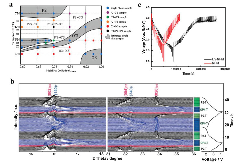
3.3. Other biphasic materialsExcept the two classes biphasic material as above mentioned, other material with different structures were also been reported. (O3+O'3)-Na0.8Mn1/2Fe1/2O2 was synthesized using an auto-combustion method then calcined at 1000 ℃, and exhibits a capacity of 135 mA h/g [62]. Ceder's group reported the influence of different synthesis conditions using a solidstate method including temperature and sodium content on structures of the layered phases of NaxCoO2 [63]. The structures were examined by XRD analysis. Then the group designed a phase diagram of NaxCoO2 in the temperature range of 450 ℃-750 ℃ in air and for the ratios of Na and Co varying from 0.60 to 1.05 as shown in Fig. 5a. Biphasic materials even triphasic material were obtained.

|
Download:
|
| Fig. 5. (a) The phase diagram of NaxCoO2, X axis is the precursor Na:Co ratio ϕNa:Co, Y axis is the sintering temperature. Most bipahse samples contain Co3O4 component. Reproduced with permission [63]. Copyright 2014, American Chemical Society. (b) The collected in situ XRD patterns of layered-tunnel composite cathode cell during the first and second charge/discharge between 1.5 V and 4.3 V at 0.1 C. Reproduced with permission [68]. Copyright 2018, Wiley-VCH. (c) GITT profile of LS-NFM (biphase) and NFM (undoped single phase) cathodes as a function of voltage. Reproduced with permission [70]. Copyright 2018, American Chemical Society. | |
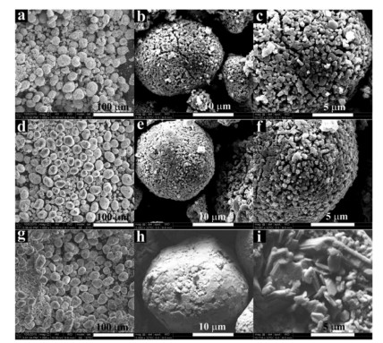
Except for the combination of two layered oxide phases, NaxNi1/6Co1/6Mn2/3O2 that has a P2-type material as a main material with a little spinel phase material was prepared [64]. When x = 0.67, the material is a pure P2 phase. When x = 0.35, 0.5, a small amount of spinel phase with the space group Fd-3 m appears. The ionic conductivity of the material is larger than the electronic conductivity, making the electronic conductivity becomes a determining factor. At the same time, the electronic conductivity that influences electrochemical performance of the mixed phase is 2 orders of magnitude higher than the pure P2 phase bringing improved rate performance. Through the SEM images (Fig. 6), we observe that the morphology differences are obvious. The size of primary particles of the mixed phase (200-500 nm) is much smaller than the pure P2 phase (1~3 μm), and the shape of P2 phase is flake-like while the mixed phase is not. It is possible that the appearance of spinel phase inhibits the agglomeration and holds back the formation of flake-shape primary particles.

|
Download:
|
| Fig. 6. SEM images of the P2/spinel intergrowth NaxNi1/6Co1/6Mn2/3O2 samples: (a-c) x = 0.35, (d-f) x = 0.50, and (g-i) x = 0.67. Copied with permission [64]. Copyright 2016, the Electrochemical Society. | |
Among layered oxides, the P2-Na0.7MnO2 with high theoretical capacity and low cost and toxicity is an ideal candidate. But the Jahn-Teller effect of the Mn(Ⅲ) causes capacity degradation [65], and the 2D migrating pathway also restrict the rate performance to some extent [66]. Yet the tunnel-type material Na0.44MnO2 has the unique 3D structure that brings excellent stability and rate performance. But its theoretical capacity is comparatively small [67]. Guo's group combined the two phases together to a stoichiometric Na0.6MnO2 composition [68]. The composite material delivers a surprisingly high capacity of 198.2 mA h/g, which is larger than either single layered or tunnel electrode. The average voltage is also elevated, so the energy density is apparently improved. In situ XRD was also conducted to find out the mechanism, as shown in Fig. 5b. The (140) and (340) peaks of the tunnel phase just shifted during the charge-discharge process. Nevertheless, the broad OP4 peak near the (002) peak appeared. Although there is a transition process, the composite recovered after 2 cycles. In summary, the biphase material integrated the advantages of the layered oxide and tunnel phase, synergetic effect played a positive role between them.
For O3 type materials, Na(NixFeyMnz)O2 is a kind of promising material [69]. The Fe, Mn elements is abundant and nontoxic, and Ni may have a positive effect on improving operating voltage. Nevertheless, the problems including cycling stability and the phase transition at high voltage need to be solved. Under this situation, Deng and coworkers introduced an O3/spinel intergrowth material Na0.87Li0.25Ni0.4Fe0.2Mn0.4O2+δ with substitution of Li [70]. The discharge capacity, capacity retention and Coulombic efficiency are all raised than the unsubstituted NaNi0.4Fe0.2Mn0.4O2 material. Over the GITT results (Fig. 5c), the biphase material exhibits a faster Na+ diffusion coefficient. The promoted diffusivity possibly because the 3D pathways in the spinel phase provide direct diffusion channel for Na+ that shorten the diffusion distance between layered and spinel components. At the same time, the plateau above 4 V of the voltage profile and the redox couples of the X-ray absorption spectroscopy (XAS) results present good reversibility, these presumably are associated with the biphasic structure.
From the three examples as above proposed, the spinel/tunnel phase may play a constructive role on accelerating ionic transformation in some occasion, due to its particular 3D pathway. Combining spinel/tunnel phase to modify available layered oxide materials is a fresh method in promoting the performances of the sodium ion battery cathodes.
Some presented the mechanism that made the biphasic materials cells performs better clearly, there still exists synergetic effect in the biphasic materials looking forward to being digged. Also, it is hard to make a specific stoichiometric ratio biphasic material. In general, the appearance of biphasic material is mostly a coincidence. However, choosing a middle content and adjusting various temperature could help a lot.
4. Triphase materialsThe same as biphasic materials, some multiphasic materials compose of only a series of layered oxide materials, but there are also other components type like spinel type material, etc. This makes better diversification of the multiphase materials.
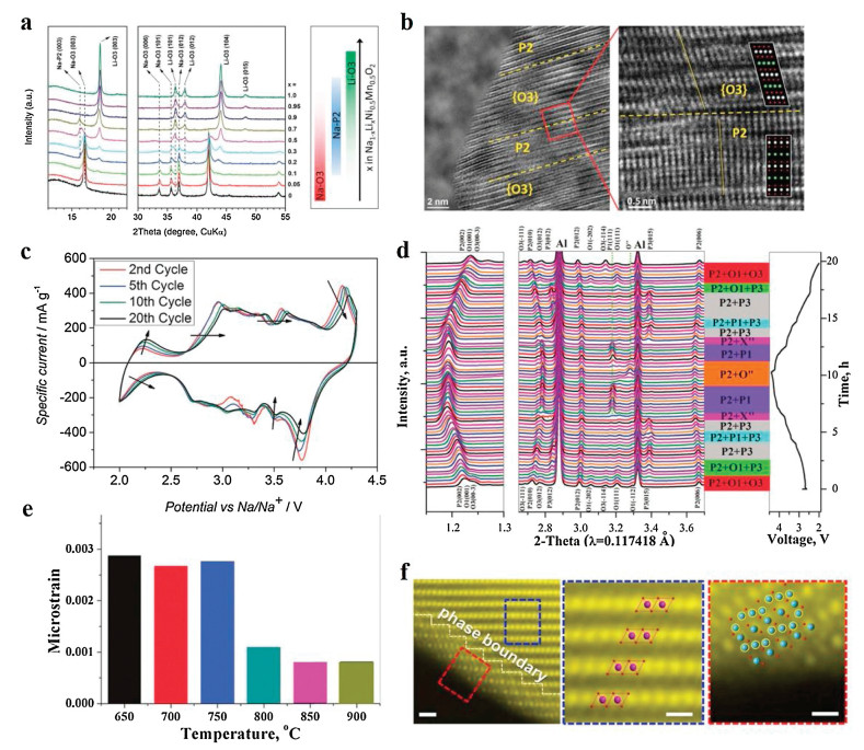
4.1. Layered oxides multiphaseLee's group has an investigation on the effect of Li substitution in NaNi0.5Mn0.5O2 material, and a series multiple layered materials Na1-xLixNi0.5Mn0.5O2+δ appear [71]. The composition of phases varies with the value of x, as shown in the XRD pattern (Fig. 7a). High-resolution TEM images (Fig. 7b) straight reveal the topotactic intergrowth of the P2 and O3 (including Na-O3, Na-O'3) phases. The capacity and rate performance increased after Li substitution. It is probably related to the P2/O3 intergrowth. After first charge-discharge process, the material transforms into P2/P3 composite, that explains the high rate performance. The hetero-epitaxy structure keeps the P3 phase stable in the mixed composite thus lowering the strain energy at the P2/P3 interface. Synergetic effect in there has played an important role.

|
Download:
|
| Fig. 7. (a) XRD patterns of Na1-xLixNi0.5Mn0.5O2+δ when Li content varies from 0 to 1 and the major phases evolution as a function of Li content is summed up by color switches in the right. Reproduced with permission [71]. Copyright 2014, Wiley-VCH. (b) High-resolution TEM images that show the P2 and O3 lattices intergrowth stacking in different magnitude. Reproduced with permission [71]. Copyright 2014, Wiley-VCH. (c) Cyclic voltammogram profile of P3/P2/O3-material for different cycle. Reproduced with permission [72]. Copyright 2015, Wiley-VCH. (d) In operando synchrotron HEXRD patterns of the P2/O3/O1-material electrode collected during the first charge/discharge cycle at 0.1 C in the voltage window of 2.0-4.4 V. Reproduced with permission [51]. Copyright 2017, the Royal Society of Chemistry. (e) On the process of in situ heating the microstrain analysis of the P2 phase in the products. Reproduced with permission [51]. Copyright 2017, the Royal Society of Chemistry. (f) The left figure is the STEM-HADDF image that directly shows the zigzag phase boundary; scale bar, 1 nm. The middle figure is the magnified image of the blue rectangle that displays the layered stacking; scale bar, 0.5 nm. The right figure is the magnified image of the red rectangle that displays the spinel-like stacking; scale bar, 0.5 nm. Reproduced with permission [77]. Copyright 2017, the authors. | |
Keller's group reported NaxMnyNizFe0.1Mg0.1O2 materials consist of single P2 phase, O3 phase and a mixture of P3/P2/O3 phase [72]. According to Rietveld refinement calculated parameters, the c axil value of P2 in the mixed phase is lower than the pure P2 on account of the higher sodium content leading to weaker repulsion of adjacent oxygen layers, and the c axil value of O3 in the mix is higher than the pure O3 for the same theory. Meanwhile the voltammogram (Fig. 7c) of the mixed phase have features in common. Overall, the mixed phase reveals higher capacity than P2, better cyclability than O3 and always delivers highest specific capacities among them in different rate. This mixed material has a synergetic effect that combines the advantages of various phases and achieve better electrochemical performances.
In 2017, Xu et al. reported triphasic P2/O1/O3 material, biphasic P2/O3 material and pure P2 phase material, all denoted as NaxNi1/3Co1/3Mn1/3O2 [51]. The biphase material also performs better than the pure P2 phase, but the triphase is even better. Triphase material embodies the best electrochemical performance. It delivers 142.8 mAh/g for the initial discharge capacity, appears a high first Coulombic efficiency of 95% along with a high capacity retention of 93% up to 50 cycles at 15 mA/g. And the rate performance of the triphase material is greatly enhanced. To find more, in operando synchrotron HEXRD (Fig. 7d) was conducted. It can be seen that the P2 diffraction peaks just shift even charged to a high voltage of 4.4 V, and no P2-O2 transition is discovered, which means the P2-O2 transition at high voltage is inhibited. Meanwhile, the O1/O3 structure experiences a reversible change during charge-discharge process. However, the transition of the biphase and pure P2 phase material is not reversible. During the research, the author found that the biphase material exhibits a sudden capacity degradation for the original few cycles but then stabilizes. This mainly due to the O3-P3 transition exists an energy barrier. The P2/O3 material cannot change back but become P2/P3 biphase after the first few cycles. Yet, the new P2/P3 biphase may be a heteroepitaxial structure and thus lessen the microstrain for the interface of P2/P3 the same as reported by Lee's group. Furthermore, part of the O1 phase diffraction peaks in the triphase material disappeared after cycling for 100 cycles, implying that the P2/O1/O3 structure may convert to P2/O3 bit by bit after deep cycling, and then it behaves the same as P2/O3 biphase material as previously mentioned. The triphase material is not a mechanical mixture, it is a series of intergrowth structures with topotactic layers, that may reduce the interfacial microstrain. So interfacial microstrain analysis was conducted (Fig. 7e). It is obvious that the triphase structure (at high temperature) interface microstrain is the lowest, and even when it is charged to 4.4 V to form the P2/O3 structure, the microstrain is still low. This research not only synthesized new biphase and triphase material with good electrochemical performances, but also explore the mechanism of the multiphase material, which hinder the P2-O2 transition and promote the O1/O3 structure stability. In addition, they focus on the interfacial microstrain simultaneously, which is a new perspective to solve problems.
As mentioned above, Na0.62Li0.18Mn0.66Ni0.17Co0.17O2 with P3/ P2/O'3 three phases composite was synthesized [59]. In fact, the O'3 phase is a Li-O'3 structure. The first charge capacity of the triphase material is the highest and the cycling stability as well as the rate performance are enhanced. The author explains that the synergetic effect can activate more sodium sites and when charge to high voltage, partial Li+ may participate in the reaction.
The mechanism was investigated more in this part. It is verified that hetero-epitaxy structure exists in triphase materials and thus diminish the interface microstrain, so it is induced that the same mechanism occurs in biphase materials as well. The combination of different phases manifests their merits respectively.
4.2. Layered oxides/spinel multiphase materialsSome multiphase materials contain layered oxide structure and spinel like structure. The spinel phase accelerated the electron transport, thus improving the electrochemical performance.
Recently, many efforts have been made about layered manganese-based oxides, because it is low-cost and environmentally friendly [27, 73, 74]. But there also exists many problems, for example, it is sensitive to air and moisture, and the disproportionation of the Mn(Ⅲ) is seriously detrimental [75, 76]. Guo and coworkers introduced an environmentally stable interface of layered oxide cathodes NaMn0.8Ti0.1Ni0.1O2 [77]. In the core of the material, it is composed of P2 and O'3 biphase structure. The Ti (Ⅲ) concentrated on the particle surface and is a spinel-like covering with atomic-scale thickness, it can be seen in the TEM pattern (Fig. 7f). The concentrated Ti spinel layer can protect the material from humid environment. After exposed to moist air for 3 days, the material still maintains its original structure (in contrast, H2O inserted the NaMnO2 structure). The disproportionation of the Mn(Ⅲ) has also been reduced since the spinel phase blocked the contact with air/electrolyte. According to the impedance spectra, the Rct of the triphase material is smaller, indicating the charge transfer on the surface is increased. This may be because the spinel-like structure exists 3D channels for sodium migration. Combined all the structural advantages, the electrochemical performance is fine. It delivers 186 mA h/g at 0.1 C. A good capacity retention of 81% is achieved after 500 cycles at 5 C (1000 mA/g), and the Coulombic efficiency for the entire course is ~98%.
Later, Hou and coworkers designed a stable layered P2/P3 and spinel intergrowth nanocomposite material Na0.5[Ni0.2Co0.15Mn0.65]O2 [78]. It delivers 177.6 mA h/g at 0.1 C, and the retention is 87.6% after 100 cycles at 0.1 C. Through ex situ XRD test, phase transition cannot be discovered. It is interesting that the (311) diffraction peak of the spinel phase shifted, indicating the Na+ can de/intercalation in the phase. The spinel phase has a 3D Na+ diffusion pathway and this may improve the kinetics of Na+ diffusion for the triphasic material. Besides, the full cell of the cathode and hard carbon also performs well, demonstrating it is a promising cathode candidate for sodium ion batteries.
The synergetic effect plays an important role in the multiphase materials with layered oxides and spinel phase, they show special properties. One kind of mechanism is that spinel phase is active during the electrochemical process, and spinel phase has a 3D pathway that improves the kinetics of Na+ diffusion. And the synergetic effect plays among the various structures. The other mechanism is when the spinel phase is not electrochemically active, then it is protective for the layered oxides.
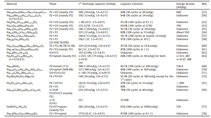
In general, the occurrence of biphase and multiphase most comes from accident. Yet their properties are outstanding. When synthesizing, people always use a middle chemical composition and middle temperature in-between different pure phases with a lot of efforts. All the biphase or multiphase materials mentioned in this article are summarized in the Table 1, listing their stoichiometric ratio, phase composition, 1st discharge capacity, capacity retention and energy density if it is mentioned.
|
|
Table 1 The stoichiometric ratio, phase composition, 1st discharge capacity, capacity retention and energy density of the biphase and multiphase materials mentioned in articles. |
In summary, we have reviewed the recent progress of multiphase cathode materials of SIBs. Although different phase materials have been deeply investigated, the research of multiphase materials have not been well discussed. Combining the advantages of different classic types of layered transition metal oxides including P2, O3 and P3 phases, satisfying comprehensive sodium storage performances can be achieved for multiphase cathode materials with the synergetic effect of multiphase. The synergetic effect can be contributed to O phase serving as a sodium reservoir and P phase allowing the fast sodium ion migration in the bulk. In detail, the phase interface stress of the heteroepitaxial structure of the multiphase cathodes suppress the phase transformation during charging-discharging. The introducing of other phases, such as layered phase and spinel-like phase, could serve as a 3D pathway to facilitate ion transportation, namely accelerating sodium ion diffusion coefficient. Furthermore, the aggregation of inactive phase component in the surface of the materials plays a protective role from the attacking of water and carbon dioxide in the atmosphere to reduce the transportation and storage costs. However, there are still many challenges to be addressed in developing layered multiphase materials, such as unpredictable synthesis conditions and insufficient understanding of the mechanism. For the future study in layered multiphase cathode materials, the exploration of controllable and precise synthesis and the providing of visual and in-depth evidences in mechanism are pivotal. For the synthesis, single phase materials prefer to form on specific component, calcination temperature and atmosphere while the multiphase materials usually form in a middle condition that is still uncertain. For the mechanism insight, more diverse characterizations, such as X-ray absorption fine structure, in situ TEM, density functional theory and so on, are further required. And the future work should also pay attention to the air or moisture stable multiphase materials, which would make a great progress on the industrialization of layered transition metal oxide cathodes. There are still many interesting works need our further exploration in layered multiphase cathode materials to push the industrialization of SIBs.Declaration of competing interest
The authors declare that there are no conflicts of interest.
AcknowledgmentsThis financial support of this work was from the National Key R & D Program of China (No. 2018YFB0104300), National Natural Science Foundation of China (Nos. 21633003, 51802149 and U1801251), NSF of Jiangsu Province, China (No. BK20170630), and the Fundamental Research Funds for the Central Universities (Nos. 021314380141 and 021314380157).
| [1] |
J. Jiang, Y. Li, J. Liu, et al., Adv. Mater. 24 (2012) 5166-5180. DOI:10.1002/adma.201202146 |
| [2] |
J. Jiang, Y. Li, J. Liu, X. Huang, Nanoscale 3 (2011) 45-58. DOI:10.1039/C0NR00472C |
| [3] |
N. Yabuuchi, K. Kubota, M. Dahbi, S. Komaba, Chem. Rev. 114 (2014) 11636-11682. DOI:10.1021/cr500192f |
| [4] |
H. Chen, T.N. Cong, W. Yang, et al., Prog. Nat. Sci. 19 (2009) 291-312. DOI:10.1016/j.pnsc.2008.07.014 |
| [5] |
B. Dunn, H. Kamath, J.M. Tarascon, Science 334 (2011) 928-935. DOI:10.1126/science.1212741 |
| [6] |
J. Liu, J.G. Zhang, Z. Yang, et al., Adv. Funct. Mater. 23 (2013) 929-946. DOI:10.1002/adfm.201200690 |
| [7] |
D. Kundu, E. Talaie, V. Duffort, L.F. Nazar, Angew. Chem. Int. Ed. 54 (2015) 3431-3448. DOI:10.1002/anie.201410376 |
| [8] |
J. Mei, T. Liao, Z. Sun, J. Energy Chem. 27 (2018) 117-127. DOI:10.1016/j.jechem.2017.10.012 |
| [9] |
M.D. Slater, D. Kim, E. Lee, C.S. Johnson, Adv. Funct. Mater. 23 (2013) 947-958. DOI:10.1002/adfm.201200691 |
| [10] |
H. Pan, Y.S. Hu, L. Chen, Energy Environ. Sci. 6 (2013) 2338. DOI:10.1039/c3ee40847g |
| [11] |
S. Guo, J. Yi, Y. Sun, H. Zhou, Energy Environ. Sci. 9 (2016) 2978-3006. DOI:10.1039/C6EE01807F |
| [12] |
X. Xiang, K. Zhang, J. Chen, Adv. Mater. 27 (2015) 5343-5364. DOI:10.1002/adma.201501527 |
| [13] |
S.W. Kim, D.H. Seo, X. Ma, G. Ceder, K. Kang, Adv. Energy Mater. 2 (2012) 710-721. DOI:10.1002/aenm.201200026 |
| [14] |
H. Kim, H. Kim, Z. Ding, et al., Adv. Energy Mater. 6 (2016) 1600943. DOI:10.1002/aenm.201600943 |
| [15] |
L. Yang, W. Wang, M. Hu, J. Shao, R. Lv, J. Energy Chem. 27 (2018) 1439-1445. DOI:10.1016/j.jechem.2017.08.021 |
| [16] |
G. Deng, D. Chao, Y. Guo, et al., Energy Storage Mater. 5 (2016) 198-204. DOI:10.1016/j.ensm.2016.07.007 |
| [17] |
D. Yuan, X. Liang, L. Wu, et al., Adv. Mater. 26 (2014) 6301-6306. DOI:10.1002/adma.201401946 |
| [18] |
J. Billaud, R.J. Clément, A.R. Armstrong, et al., J. Am. Chem. Soc. 136 (2014) 17243-17248. DOI:10.1021/ja509704t |
| [19] |
J.Y. Hwang, S.T. Myung, Y.K. Sun, Chem. Soc. Rev. 46 (2017) 3529-3614. DOI:10.1039/C6CS00776G |
| [20] |
K.B. Hueso, M. Armand, T. Rojo, Energy Environ. Sci. 6 (2013) 734-749. DOI:10.1039/c3ee24086j |
| [21] |
C. Delmas, C. Fouassier, P. Hagenmuller, Physica B+C 99 (1980) 81-85. DOI:10.1016/0378-4363(80)90214-4 |
| [22] |
S. Guo, P. Liu, H. Yu, et al., Angew. Chem. Int. Ed. 54 (2015) 5894-5899. DOI:10.1002/anie.201411788 |
| [23] |
D. Kim, S.H. Kang, M. Slater, et al., Adv. Energy Mater. 1 (2011) 333-336. DOI:10.1002/aenm.201000061 |
| [24] |
M. Guignard, C. Didier, J. Darriet, et al., Nat. Mater. 12 (2013) 74. DOI:10.1038/nmat3478 |
| [25] |
P. Vassilaras, X. Ma, X. Li, G. Ceder, J. Electrochem. Soc. 160 (2013) A207-A211. DOI:10.1149/2.023302jes |
| [26] |
J. Zhao, L. Zhao, N. Dimov, S. Okada, T. Nishida, J. Electrochem. Soc. 160 (2013) A3077-A3081. DOI:10.1149/2.007305jes |
| [27] |
X. Ma, H. Chen, G. Ceder, J. Electrochem. Soc. 158 (2011) A1307. DOI:10.1149/2.035112jes |
| [28] |
J. Xu, D.H. Lee, R.J. Clément, et al., Chem. Mater. 26 (2014) 1260-1269. DOI:10.1021/cm403855t |
| [29] |
A. Caballero, L. Hernán, J. Morales, et al., J. Mater. Chem. 12 (2002) 1142-1147. DOI:10.1039/b108830k |
| [30] |
N. Yabuuchi, H. Yoshida, S. Komaba, Electrochemistry 80 (2012) 716-719. DOI:10.5796/electrochemistry.80.716 |
| [31] |
J. Zhao, L. Zhao, N. Dimov, S. Okada, T. Nishida, J. Electrochem. Soc. 160 (2013) A3077-A3081. DOI:10.1149/2.007305jes |
| [32] |
N. Yabuuchi, M. Kajiyama, J. Iwatate, et al., Nat. Mater. 11 (2012) 512-517. DOI:10.1038/nmat3309 |
| [33] |
P.F. Wang, H.R. Yao, X.Y. Liu, et al., Adv. Mater. 29 (2017) 1700210. DOI:10.1002/adma.201700210 |
| [34] |
S. Guo, Y. Sun, P. Liu, et al., Sci. Bull. 63 (2018) 376-384. DOI:10.1016/j.scib.2018.02.012 |
| [35] |
P.F. Wang, Y. You, Y.X. Yin, Y.G. Guo, J. Mater. Chem. A 4 (2016) 17660-17664. DOI:10.1039/C6TA07589D |
| [36] |
D.H. Lee, J. Xu, Y.S. Meng, Phys. Chem. Chem. Phys. 15 (2013) 3304-3312. DOI:10.1039/c2cp44467d |
| [37] |
H. Wang, B. Yang, X.Z. Liao, et al., Electrochim. Acta 113 (2013) 200-204. DOI:10.1016/j.electacta.2013.09.098 |
| [38] |
Q.C. Wang, J.K. Meng, X.Y. Yue, et al., J. Am. Chem. Soc. 141 (2019) 840-848. DOI:10.1021/jacs.8b08638 |
| [39] |
P.F. Wang, Y. You, Y.X. Yin, et al., Angew. Chem. Int. Ed. 55 (2016) 7445-7449. DOI:10.1002/anie.201602202 |
| [40] |
X. Wu, J. Guo, D. Wang, et al., J. Power Sources 281 (2015) 18-26. DOI:10.1016/j.jpowsour.2014.12.083 |
| [41] |
G. Singh, N. Tapia-Ruiz, J.M. Lopez Del Amo, et al., Chem. Mater. 28 (2016) 5087-5094. DOI:10.1021/acs.chemmater.6b01935 |
| [42] |
C. Fouassier, C. Delmas, P. Hagenmuller, Mater. Res. Bull. 10 (1975) 443-449. DOI:10.1016/0025-5408(75)90166-X |
| [43] |
J. Deng, W.B. Luo, X. Lu, et al., Adv. Energy Mater. 8 (2018) 1701610. DOI:10.1002/aenm.201701610 |
| [44] |
S. Ivanova, E. Zhecheva, R. Kukeva, et al., J. Phys. Chem. C 120 (2016) 3654-3668. |
| [45] |
M.L. Kalapsazova, E.N. Zhecheva, G.T. Tyuliev, et al., J. Phys. Chem. C 121 (2017) 5931-5940. DOI:10.1021/acs.jpcc.6b12887 |
| [46] |
B. Song, E. Hu, J. Liu, et al., J. Mater. Chem. A 7 (2019) 1491-1498. DOI:10.1039/C8TA09422E |
| [47] |
X. Rong, J. Liu, E. Hu, et al., Joule 2 (2018) 125-140. DOI:10.1016/j.joule.2017.10.008 |
| [48] |
M. Kalapsazova, G.F. Ortiz, J.L. Tirado, et al., ChemPlusChem 80 (2015) 1642-1656. DOI:10.1002/cplu.201500215 |
| [49] |
Y. Wang, X. Wang, X. Li, et al., Chem. Eng. J. 360 (2019) 139-147. DOI:10.1016/j.cej.2018.11.214 |
| [50] |
Z.Y. Li, J. Zhang, R. Gao, et al., J. Phys. Chem. C 120 (2016) 9007-9016. DOI:10.1021/acs.jpcc.5b11983 |
| [51] |
G.L. Xu, R. Amine, Y.F. Xu, et al., Energy Environ. Sci. 10 (2017) 1677-1693. DOI:10.1039/C7EE00827A |
| [52] |
X. Qi, L. Liu, N. Song, et al., ACS Appl. Mater. Interfaces 9 (2017) 40215-40223. DOI:10.1021/acsami.7b11282 |
| [53] |
M. Bianchini, E. Gonzalo, N.E. Drewett, et al., J. Mater. Chem. A 6 (2018) 3552-3559. DOI:10.1039/C7TA11180K |
| [54] |
D. Kim, S.H. Kang, M. Slater, et al., Adv. Energy Mater. 1 (2011) 333-336. DOI:10.1002/aenm.201000061 |
| [55] |
G.K. Veerasubramani, Y. Subramanian, M.S. Park, et al., Electrochim. Acta 296 (2019) 1027-1034. DOI:10.1016/j.electacta.2018.11.160 |
| [56] |
L.G. Chagas, D. Buchholz, L. Wu, B. Vortmann, S. Passerini, J. Power Sources 247 (2014) 377-383. DOI:10.1016/j.jpowsour.2013.08.118 |
| [57] |
L.G. Chagas, D. Buchholz, C. Vaalma, L. Wu, S. Passerini, J. Mater. Chem. A 2 (2014) 20263-20270. DOI:10.1039/C4TA03946G |
| [58] |
X. Chen, X. Zhou, M. Hu, et al., J. Mater. Chem. A 3 (2015) 20708-20714. DOI:10.1039/C5TA05205J |
| [59] |
Q. Huang, S. Xu, L. Xiao, et al., Inorg. Chem. 57 (2018) 15584-15591. DOI:10.1021/acs.inorgchem.8b02931 |
| [60] |
Y.N. Zhou, P.F. Wang, Y.B. Niu, et al., Nano Energy 55 (2019) 143-150. DOI:10.1016/j.nanoen.2018.10.072 |
| [61] |
Z. Yan, L. Tang, Y. Huang, et al., Angew. Chem. Int. Ed. 58 (2019) 1412-1416. DOI:10.1002/anie.201811882 |
| [62] |
B. Mortemard de Boisse, D. Carlier, M. Guignard, C. Delmas, J. Electrochem. Soc. 160 (2013) A569-A574. DOI:10.1149/2.032304jes |
| [63] |
Y. Lei, X. Li, L. Liu, G. Ceder, Chem. Mater. 26 (2014) 5288-5296. DOI:10.1021/cm5021788 |
| [64] |
J. Zheng, P. Yan, W.H. Kan, C. Wang, A. Manthiram, J. Electrochem. Soc. 163 (2016) A584-A591. DOI:10.1149/2.0041605jes |
| [65] |
S. Kumakura, Y. Tahara, S. Sato, K. Kubota, S. Komaba, Chem. Mater. 29 (2017) 8958-8962. DOI:10.1021/acs.chemmater.7b02772 |
| [66] |
J. Billaud, G. Singh, A.R. Armstrong, et al., Energy Environ. Sci. 7 (2014) 1387-1391. DOI:10.1039/C4EE00465E |
| [67] |
Y. Wang, J. Liu, B. Lee, et al., Nat. Commun. 6 (2015) 6401. DOI:10.1038/ncomms7401 |
| [68] |
Y. Xiao, P.F. Wang, Y.X. Yin, et al., Adv. Energy Mater. 8 (2018) 1800492. DOI:10.1002/aenm.201800492 |
| [69] |
H. Wang, X.Z. Liao, Y. Yang, et al., J. Electrochem. Soc. 163 (2016) A565-A570. DOI:10.1149/2.0011605jes |
| [70] |
C. Deng, P. Skinner, Y. Liu, et al., Chem. Mater. 30 (2018) 8145-8154. DOI:10.1021/acs.chemmater.8b02614 |
| [71] |
E. Lee, J. Lu, Y. Ren, et al., Adv. Energy Mater. 4 (2014) 1400458. DOI:10.1002/aenm.201400458 |
| [72] |
M. Keller, D. Buchholz, S. Passerini, Adv. Energy Mater. 6 (2016) 1501555. DOI:10.1002/aenm.201501555 |
| [73] |
N. Yabuuchi, M. Kajiyama, J. Iwatate, et al., Nat. Mater. 11 (2012) 512. DOI:10.1038/nmat3309 |
| [74] |
N. Yabuuchi, S. Komaba, Sci. Technol. Adv. Mater. 15 (2014) 043501. DOI:10.1088/1468-6996/15/4/043501 |
| [75] |
E. Talaie, V. Duffort, H.L. Smith, B. Fultz, L.F. Nazar, Energy Environ. Sci. 8 (2015) 2512-2523. DOI:10.1039/C5EE01365H |
| [76] |
J. Lu, C. Zhan, T. Wu, et al., Nat. Commun. 5 (2014) 5693. DOI:10.1038/ncomms6693 |
| [77] |
S. Guo, Q. Li, P. Liu, M. Chen, H. Zhou, Nat. Commun. 8 (2017) 135. DOI:10.1038/s41467-017-00157-8 |
| [78] |
P. Hou, J. Yin, X. Lu, et al., Nanoscale 10 (2018) 6671-6677. DOI:10.1039/C8NR00650D |