 2020, Vol. 31


b Institute of Zhejiang University-Quzhou, Quzhou 324000, China;
c Institute of Nanoscience and Nanotechnology, College of Physical Science and Technology, Central China Normal University, Wuhan 430079, China;
d School of Materials Science and Engineering, Zhejiang University, Hangzhou 310027, China;
e Nation & Local United Engineering Laboratory for Power Batteries, Faculty of Chemistry, Northeast Normal University, Changchun 130024, China;
f Shanghai Synchrotron Radiation Facility, Shanghai Advanced Research Institute, Chinese Academy of Sciences, Shanghai 201204, China;
g Ningbo Research Institute, Zhejiang University, Ningbo 315100, China
The Li–O2 batteries are promising next-generation energy storage systems due to their high energy density, which is two to three times greater than that of lithium-ion cells [1-3]. A typical Li–O2 cell comprises a lithium anode, a nonaqueous electrolyte and a porous cathode, which is usually based on a carbon material [4-6]. The nonaqueous Li–O2 cells mostly use dimethyl sulfoxide (DMSO) [7] and tetraglyme [5] as electrolyte solutions, which are relatively stable in the voltage range of 2.0–4.5 V vs. Li+/Li. It is generally believed that the reaction process during discharge is as follows [1, 8]:
Anode:

|
(1) |
Cathode:

|
(2) |
|
(3) |

|
(4) |
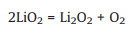
Superoxide lithium (LiO2), as an important intermediate in the discharge process, is insoluble and further decomposes to O2 and Li2O2 (the main discharge product) on the electrode surface. The discharge process is terminated by blocking the electrode surface with precipitated Li2O2 [4]. In the charge process, solid Li2O2 on the cathode is directly oxidized to decompose at the high charging voltage (> 4.3 V vs. Li+/Li) [9] due to its poor conductivity and insolubility, which also lead to low energy efficiency (limit to ~60% to 70%) [9, 10], poor cyclic stability, and irreversible decomposition of carbon materials and electrolyte. As one of the major challenges facing the Li–O2 cell [11, 12], finding ways to decompose Li2O2 at a low charging voltage is quite significant for improving the overall performance [13].
To efficiently decompose solid Li2O2 during the charge process, various solid catalysts, such as noble metals [14-16], metal oxides [17, 18] and carbon materials doped with N and S [19, 20], have been developed. However, the active sites on the above solid catalysts are gradually covered by the Li2O2 particles. Due to the inadequate contact between solid–solid particles [13, 21] and the poor electrical conductivity of Li2O2, the transport of electrons between Li2O2 particles and the electrode surface is very slow during the charge process, which leads to further high electrochemical polarization at the cathode. Compared with all kinds of heterogeneous catalysts, dissolved redox mediators (RMs) are more mobile and inclined to stably transform between RM+ and RM in an electrolyte, which results in its unique advantage of electronic conduction. Therefore, a RM achieves faster and more effective transport of electrons by reversible redox pairs when dissolved in an electrolyte, making it more accessible to discharge products and the cathode [22, 23]. The charge process without a RM on the cathode proceeds through the following step:

|
(5) |
The charge process with a RM on the cathode proceeds through the following steps [13, 24]:

|
(6) |

|
(7) |
To oxidize Li2O2, the redox potential of the RM+/RM couple needs to be higher than 2.96 V (theoretical voltage of forming Li2O2). Additionally, for maximization of energy efficiency, the redox potential of RM+/RM should not be much higher than 2.96 V. Therefore, a voltage in the range of 3.0–4.0 V (vs. Li+/Li) is recognized as the reasonable range for promising RM candidates [21]. The electrochemical decomposition of Li2O2 at the cathode during the charge process usually requires a voltage higher than 4.3 V without a RM. However, during the charge reaction with a RM, the RM is first oxidized to the RM+ at the cathode at a lower voltage (ERM+/RM) than 4.3 V. Then the RM+ oxidizes and decomposes Li2O2 particles by a chemical reaction. Meanwhile, the RM+ is reduced to the RM for regeneration. The decomposition of Li2O2 is transformed from a direct electrochemical pathway (step 5) to a chemical reaction (steps 6–7) by adding a RM [21].
In addition to a suitable potential of the redox pair, a possible RM should meet many applied requirements, such as good solubility in the electrolyte and good chemical stability in the electrochemical environment. To date, a few RMs have been reported to reduce electrochemical polarization during the charge process. For example, tetrathiafulvalene (TTF), lithium iodide (LiI) [13, 25], and 2, 2, 6, 6-tetramethylpiperidinyloxyl (TEMPO) have been applied to a Li–O2 battery. The cells with TTF and LiI showed a favorable ability to lower the charge voltage during the first cycle, while the overpotential rapidly increased with continuous discharge/recharge cycles. Additionally, it is widely reported that LiI is reduced by Li metal, which depletes both the redox mediator and the anode [26]. TEMPO with ketjen black showed a more stable cycling performance than LiI and TTF under the same testing conditions; however, the life of the cell with TEMPO was less than 50 cycles. The reported RMs are faced with poor cyclic stability in Li–O2 batteries.
Recently, research based on multivalent ferric organics as redox mediators has received increasing attention [27]. For example, Sun et al. [23] found that soluble iron phthalocyanine (FePc) shows good cyclic stability. Ferrocene (Fec) has also been reported as a RM in Li–O2 batteries; however, the CV and DEMS results show poor reversibility and stability [12]. Lim et al. [21] describe that the ionization energy (I.E.) values of RM molecules are directly related to the redox potential of the RM. Solid ruthenium and ruthenic oxide (Ru/RuO2) [28, 29] at the cathode exhibit an excellent ability to catalyze the Li2O2 decomposition during the charge process. Moreover, the I.E. value of RuⅢ/RuⅡ is close to that of FeⅢ/FeⅡ, which means that multivalent ruthenium organics may possess a suitable redox potential to act as possible RMs.
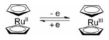
Here, we first report ruthenocene (Ruc) as a highly stable redox mediator to reduce the charging voltage and greatly increase the cycling life of Li–O2 batteries. The molecular structure and valance change of ruthenocene were shown in Scheme 1. During the electrochemical reaction, the valance of ruthenium as a center atom was changed between ruthenium(Ⅱ) and ruthenium(Ⅲ). To primarily judge Ruc as a possible candidate, the redox potential and the reversibility of Ruc in a Li–O2 cell environment were explored by cyclic voltammetry (CV). The first discharge and recharge curves of Li–O2 cells with and without Ruc are displayed, and their discharge/recharge potential platforms were compared. Additionally, the cycling life of Li–O2 cells with and without Ruc was investigated under the same conditions.

|
Download:
|
| Scheme 1. The molecular structure and valance change of ruthenocene. | |
Scanning electron microscopy (SEM) and X-ray diffraction (XRD) were used to observe the form, number and crystalline phase changes of the products on the cathode of Li–O2 batteries after full discharge and recharge, respectively. To explore the amount and components of the discharge products after different discharge and recharge cycles, X-ray photoelectron spectroscopy (XPS) was recorded and analyzed. Finally, free energy profiles of possible active sites and reaction mechanisms with Ruc were calculated and compared, which further explained why Ruc can reduce the charge voltage and enhance the cyclic stability in a Li–O2 battery.
The appropriate redox potential of RM means the RM has the ability to decompose Li2O2 and maximize energy efficiency. Thus, possessing a suitable redox potential is the primary condition that possible RM candidates must meet.
To explore the redox potential and the reversibility of Ruc, cyclic voltammetry (CV) was performed. During the CV test, a polished gold piece, a platinum wire and a silver wire were used as the working electrode, counter electrode and reference electrode, respectively.
From Fig. 1a, the formal potential of the redox couple O2/O2- was 2.36 V (vs. Li+/Li) in DMSO, which is consistent with previous reports. A formal voltage of 3.59 V was determined for the redox pair Ruc+/Ruc, which is consistent with the midpoint between the anodic and cathodic peaks [30]. The CV curves of Ruc show redox potentials (3.59 V vs. Li+/Li) greater than 2.96 V (theoretical voltage for forming Li2O2), which indicates that Ruc possesses a sufficiently high redox potential to oxidize Li2O2. The redox peak of Ruc+/Ruc in Ar is identical to that in O2 atmosphere, which shows that Ruc does not react with oxygen. Additionally, for the redox pair of Ruc+/Ruc in Fig. S1 (Supporting information), the ratio of the reduction peak current (Ip, c) and the oxidation peak current (Ip, a) is close to 1 (Ip, c/Ip, a = 0.92), which confirms the reversible redox pair of Ruc+/Ruc. The cathodic to anodic peak separation for Ruc is 68 mV (Fig. S1 in Supporting information), which is very close to 59 mV recognized for a reversible one-electron transfer process [30].
We evaluated the electrochemical function of Ruc as a redox mediator by assembling full Li–O2 cells to assess its practical advantages (Figs. 1b and c). To focus purely on the contribution of Ruc as an electron shuttle to reduce the charge potential and prolong the cycling life of Li–O2 batteries, we used ketjen black as a cathode material without other solid catalysts. Li metal was used as the negative electrode (anode). Fig. 1b shows the first discharge/ charge cycle of the Li–O2 batteries with (red) and without (black) 0.01 mol/L Ruc in 0.1 mol/L LiTFSI/tetraglyme at current density of 0.1 mA/cm2 and capacity of 500 mAh/g. Although the cell with Ruc shows a similar discharge voltage platform as that without RM, the charge potential platform was significantly reduced with Ruc to 3.65 V, a decrease of up to 610 mV, which indicates that Ruc, as a redox mediator, can actually reduce the charging potential of Li–O2 batteries.

|
Download:
|
| Fig. 1. (a) Cyclic voltammetry of 5 mmol/L Ruc dissolved in 0.1 mol/L TBAClO4 in DMSO. (b) The first charge/discharge curves. (c) Cycling stability of a Li–O2 cell; with (the red) and without (the black) Ruc. (d) Cycling stability comparison of several common RMs with a KB cathode at the same test condition. | |
To further examine the cycling stability of the RM in batteries between 2.0–4.5 V at current density of 0.1 mA/cm2 and limited capacity of 500 mAh/g, the cycling stability of Li–O2 batteries with and without Ruc was tested, and the results are shown in Fig. 1c. The Li–O2 batteries with Ruc showed superior stability and achieved 83 cycles with a pure KB electrode. Moreover, for the Li–O2 batteries without Ruc, only 23 stable cycles were possible, which are far less than those with Ruc. The cell with Ruc still maintained a low charge voltage after multiple cycles. The remarkable cycling life of the Li–O2 cell with Ruc benefits from the high stability of Ruc, which is significant for the practical application of a redox mediator.
In addition to comparing the cell without Ruc, the cycling stability of several RMs reported according to previous articles was compared, and the results are shown in Fig. 1d. All RMs were compared under the same test conditions, including electrode materials, current density, and specific capacity. The cells with 0.01 mol/L TTF, LiI and TEMPO performed well for 27, 20 and 50 cycles, respectively, with a pure KB electrode, and the cycling performance is much lower than that of Ruc in Li–O2 batteries. This result indicates that Ruc, as a unique redox mediator, provides remarkable stability, which greatly contributes to the cycle life of Li–O2 batteries.
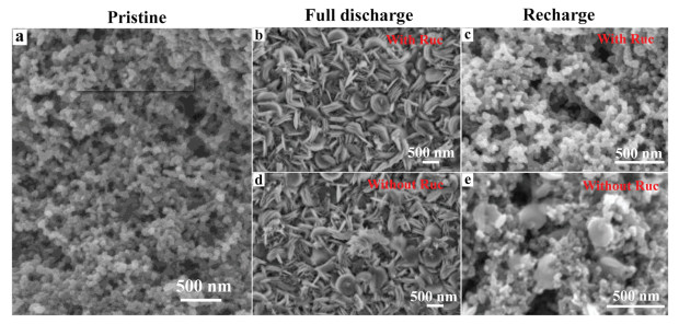
In order to further assess the ability of Ruc to dissolve in the electrolyte to decompose solid Li2O2 during the charge process, we used scanning electron microscopy (SEM) to investigate the form and amount of discharge products on the cathode after full discharge and recharge with and without Ruc. The SEM images were collected from the cathode of the Li–O2 cell with and without 0.01 mol/L Ruc in 0.1 mol/L LiTFSI/tetraglyme at current density of 0.1 mA/cm2. The Li–O2 cell was discharged to 2.5 V and subsequently charged to 4.5 V. The SEM images of the pristine cathode (Fig. 2a), the cathodes after full discharge and recharge with Ruc (Figs. 2b and c, respectively), and the cathodes after full discharge and recharge without Ruc (Figs. 2d and e, respectively) are shown.

|
Download:
|
| Fig. 2. SEM images of the KB electrodes after different discharge capacities in Li–O2 cells. (a) Pristine, (b) full discharge with Ruc, (c) recharge with Ruc, (d) full discharge without Ruc, (e) recharge without Ruc. | |
The full discharge and recharge pristine cathode consists of porous KB carbon, so the porous structure on the cathode is shown in Fig. 2a. After the full discharge process with and without Ruc, the surface of the cathode is completely covered by sheet discharge products. No porous KB materials were observed, as shown in Figs. 2b and d. The discharge products gradually decomposed during the charge process. From Fig. 2c, the cathode of the cell with Ruc was almost free of coverage of discharge products after recharging. However, the discharge product was only partially decomposed in the absence of Ruc at the same charge voltage (4.5 V) (Fig. 2e). Comparing the SEM images after recharge with and without Ruc shows that Ruc as the redox mediator contributes to decomposition of the discharge products.
To further explore the chemistry of the discharge products on the cathode surface and compare the reversibility of cells without and with Ruc, we used X-ray photoelectron spectroscopy (XPS) to examine the cathode in the O 1s (Figs. 3a and b) and Ru 3p (Fig. 3c) regions after different discharge/recharge cycles [36]. Due to the short cycling life of the Li–O2 batteries without Ruc, only the 1st, 5th and 10th cycle XPS spectra in the O 1s region are shown in Fig. 3a. In Fig. 3b, we show the XPS results for the pristine cathode in the O 1s region with Ruc and those after the 1st, 10th and 30th cycles. Typically the C-O (532 eV) [31] and C = O (533.2 eV) [32] features were related to the KB material in the pristine cathode. Additionally, the main discharge product, Li2O2, was detected at 531.4 eV [31, 32]. The Li2O2 peak appeared after discharging, and then, the Li2O2 peak decreased or disappeared as Li2O2 decomposed during the charge process. Features related to Li2CO3 (532.6 eV) [33, 34] are apparent for the degradation of carbon materials and electrolytes in the continuous cycling process [31, 32].

|
Download:
|
| Fig. 3. (a) O 1s XPS obtained on the air cathode of the cell without Ruc from the 1st, 5th, 10th discharge/recharge cycle electrodes. (b) O 1s XPS obtained on the air cathode of the cell with Ruc from the 1st, 10th, 30th discharge/recharge cycle electrodes. (c) Ex situ XPS obtained from the 80th cycle charged electrodes collected in the Ru 3p region. (d) Ex situ XRD collected from the pristine (the black), full discharged to 2.0 V and recharged to 4.5 V electrodes with (the green) and without Ruc (the red); black stars are symbols as Li2O2. | |
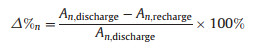
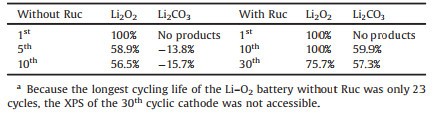
Based on the XPS results in the O 1s region, we assessed the amount of Li2O2 by calculating the ratio of the integral area of Li2O2 to the total integral area in the O 1s region, and the results are shown in Table S1 (Supporting information). The same strategy was applied to assess the amount of Li2CO3 as well. To better compare the change in the Li2O2(Li2CO3) amount after every cycling recharge, the change ratio (decomposition percentage, △%) of Li2O2(Li2CO3) after every recharge with and without Ruc was calculated by the following equation:
|
where n is the cycle number, An, discharge and An, recharge are the Li2O2(Li2CO3) residue amount after the nth discharge and recharge cycle, respectively, which are listed in Table S1.
All results of the change ratio are shown in Table 1. After the 5th and 10th recharge cycles without Ruc, the Li2O2 peak was still observed in Fig. 3a, and the change ratios of Li2O2 were merely 58.9% and 56%, respectively. However, after the 1st and 10th recharge cycles with Ruc, there was no Li2O2 peak, as shown in Fig. 3b, and the change ratio of Li2O2 after recharging with Ruc was 100% (Table 1). After the 30th recharge cycle with Ruc, the change ratio of Li2O2 was still higher than 75%. Even after a long cycle time, Ruc as the RM provided a remarkable ability to stably decompose Li2O2.
|
|
Table 1 The decomposition percentage of Li2O2 and Li2CO3 after recharge during cycling with and without Ruc according to the XPS data in the O 1s region.a |
From Fig. 3 and Table 1, as the cycle number increased, the Li2CO3 peak gradually became more obvious due to its accumulation during the cycling process. As shown in Table 1, the change ratios of decomposed Li2CO3 were -13.8% and -15.7% after the 5th and 10th recharge cycles without Ruc, respectively. These negative change ratios indicate that some electrode materials or electrolytes decomposed partly at high charge potentials. Interestingly, the Li2CO3 peak became weak after the 10th and 30th recharge cycles with Ruc in Fig. 3b, and the change ratios of decomposed Li2CO3 were 60% and 57.3%, respectively. By comparing the change ratios of Li2O2 and Li2CO3 with and without Ruc, we determined that adding Ruc favors decomposition of Li2O2 during long cycle time and decomposition of Li2CO3 to some degree. Therefore, in the Li–O2 batteries with Ruc, less Li2O2 and Li2CO3 residue accumulated on the surface of the cathode during the cycling process.
In practical terms, ruthenium was also used as the solid catalyst to accelerate the decomposition of Li2O2 on the cathode. To explore whether decomposition of Li2O2 results from soluble Ruc rather than a solid containing Ru from Ruc deposition, we performed XPS analysis on the cathode cycled 80 times in the Ru 3p region, as shown in Fig. 3c. There were no Ru 3p peaks observed from the 80th recharge cycle electrode, indicating that the Ruc molecule was not deposited and existed in the electrolyte as a soluble catalyst.
The XPS results above show the catalytic stability of Ruc during long cycle time with specific capacities. To further explore the ability of Ruc to decompose the discharge products after full discharge, XRD analysis (Fig. 2d) was investigated after discharging to 2.0 V and subsequently recharging to 4.5 V. Approximately equal strength peaks of Li2O2 (black star symbol) were observed after fully discharging with and without Ruc. As the charge process continued, there was almost no obvious Li2O2 peak recorded with Ruc. However, the Li2O2 residue was still detectable after recharging to a voltage of 4.5 V in the cathode without Ruc, which is coincident with the SEM results (Fig. 2) above. By comparing the XRD results after recharging with and without Ruc, we further proved that Ruc is favorable for the decomposition of Li2O2 in the potential range from 2.0 V to 4.5 V during the full discharge-charge process.
To further study the electrocatalytic activity of Ruc toward OER, in situ high resolution X-ray powder diffraction (HRXRD) experiments were conducted to monitor the Li2O2 decompositon in a cell containing Ruc as the RM with a Li2O2-based electrode. Fig. S2a (Supporting information) shows the in situ HRXRD data of the cathode collected every 40 min during the charge process at current density of 80 mA/gLi2O2. The 2θ of Li2O2 (100) and (101) peaks were 18.9° and 20.1°, respectively. Note that the intensities of Li2O2 peaks gradually decreased with raising charge time, indicating the Li2O2 degradation dominated the charge process. This is also proved by the analysis of ratio of carbon and Li2O2 based on the integrals of the peak areas, as seen in Fig. S2b (Supporting information), which indicates the positive effects of ruthenocene for eliminating Li2O2 and extending the cyclic life of Li–O2 batteries. Additionally, Figs. S2c and d (Supporting information) show the pictures of the in situ HRXRD device placed at the BL14B1 beamline of Shanghai Synchrotron Radiation Facility.
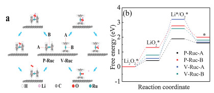
To investigate the intrinsic mechanisms of the charge process, the density functional theory (DFT)-based charge steps were studied, and their corresponding free energy profiles are shown in Fig. 4. To verify the reasonable reaction mechanisms of the mediator, vertical and parallel ruthenocene (Ruc) molecules on the surface of graphene, as two typical configurations, were considered and labeled with V-Ruc and P-Ruc, respectively. For each configuration, two possible active sites of ruthenocene, noted with A and B, were studied. In the calculations, the energy difference between the models V-Ruc and P-Ruc was 29 MeV, which indicates that there is a sufficient probability for a thermal fluctuation to drive the two configurations to transition from each other on the surface of graphene [35].

|
Download:
|
| Fig. 4. DFT-based (a) reaction pathways and (b) free energy profiles for A and B sites of the V-Ruc and P-Ruc RM models during the charge process in Li–O2 batteries. | |
The DFT-based reaction pathways during the charging process are shown in Fig. 4a. The whole reaction cycles are different for models V-Ruc and P-Ruc based on calculations. For model V-Ruc, the cycle is composed of the following elementary steps:
|
(8) |

|
(9-1) |

|
(10-1) |
For model P-Ruc, it has the same elementary step as model V-Ruc, and the other steps are as follows:

|
(9-2) |

|
(10-2) |
The free energy profiles for the A and B active sites of models V-Ruc and P-Ruc are shown in Fig. 4b. From the calculations, the charge processes are uphill reactions except the last elementary step for all the models, which means external potentials are needed to start the charge reactions. The Li2O2* dissociation process is considered as the first step in the charge reactions for all the models. The potential barriers are 0.43, 1.32, 0.58, and 0.79 eV for models P-Ruc-A, P-Ruc-B, V-Ruc-A and V-Ruc-B, respectively. Then, the second step for the P-Ruc model is LiO2* decomposition into O2* and LiO2* decomposition into Li* for the V-Ruc model. For this step, the potential barriers are 2.64, 1.81, 1.48 and 1.44 eV for V-Ruc-A, V-Ruc-B, P-Ruc-A and P-Ruc-B, respectively, which correspond to the overpotential values in the charge process [36, 37]. From the results, the potential barriers of the charge reactions on the active sites of the P-Ruc model are lower than those of the V-Ruc model. Lower potential barriers indicate the lower overpotential values of the charge reactions. Therefore, both the A and the B sites of P-Ruc are the most likely active sites in the charge process.
In conclusion, we first report that Ruc is an extremely suitable redox mediator for Li–O2 batteries. Ruc exhibits a suitable redox potential for the redox pair (Ruc+/Ruc) (3.59 V). The use of Ruc in Li–O2 batteries significantly reduced the charging voltage up to 610 mV. Additionally, compared with the poor cyclic life of the Li– O2 batteries without Ruc (23 cycles), Ruc increased the cyclic life of the Li–O2 batteries to 83 cycles. By comparing the results of SEM and XRD of the cathode after full discharge/recharge without and with Ruc, we reveal that Li2O2 was the main product and was almost entirely eliminated after recharging in the Li–O2 batteries with Ruc. The XPS results indicated that Ruc is effective at decomposing Li2O2 even after a long cycle time. Additionally, in the Li–O2 batteries without Ruc, the amount of Li2CO3 gradually increased after every recharge. Ruc contributed to the partial decomposition of Li2CO3 during the recharge process, and less product residue accumulated on the surface of the cathode with Ruc. The result of DFT-based charge steps confirms that the A and B sites of P-Ruc are the most likely active sites for the charge process.
Declaration of competing interestThe authors declare that they have no known competing financial interests or personal relationships that could have appeared to influence the work reported in this paper.
AcknowledgmentsQ. He acknowledges the financial support from the National Natural Science Foundation of China (Nos. U1732111 and 21676241), "The Recruitment Program of Global Youth Experts" from the Chinese government, and the "Hundred Talents Program" of Zhejiang University. Hubei Natural Science Foundation of China (No. 2018CFB531); Self-determined Research Funds of CCNU from Colleges' Basic Research and Operation of MOE (No. CCNU18TS045) are gratefully acknowledged.
Appendix A. Supplementary dataSupplementary material related to this article can be found, in the online version, at doi:https://doi.org/10.1016/j.cclet.2019.11.046.
| [1] |
X.W. Gao, Y.H. Chen, L.R. Johnson, et al., Nat. Energy 2 (2017) 7. |
| [2] |
Z.Q. Peng, S.A. Freunberger, Y.H. Chen, P.G. Bruce, Science 337 (2012) 563-566. DOI:10.1126/science.1223985 |
| [3] |
H. Gu, G. Wang, C. Zhu, et al., Electrochim. Acta 298 (2019) 806-817. DOI:10.1016/j.electacta.2018.12.152 |
| [4] |
D.J. Lee, H. Lee, Y.J. Kim, et al., Adv. Mater. 28 (2016) 857-863. DOI:10.1002/adma.201503169 |
| [5] |
B.J. Bergner, A. Schurmann, K. Peppler, et al., J. Am. Chem. Soc. 136 (2014) 15054-15064. DOI:10.1021/ja508400m |
| [6] |
X.W. Gao, Z.P. Jovanov, Y.H. Chen, et al., Angew. Chem. Int. Ed. 56 (2017) 6539-6543. DOI:10.1002/anie.201702432 |
| [7] |
Y.H. Chen, S.A. Freunberger, Z.Q. Peng, et al., Nat. Chem. 5 (2013) 489-494. DOI:10.1038/nchem.1646 |
| [8] |
X.W. Gao, Y.H. Chen, L. Johnson, P.G. Bruce, Nat. Mater. 15 (2016) 882-888. DOI:10.1038/nmat4629 |
| [9] |
S. Choudhury, C.T.C. Wan, W.I. Al Sadat, et al., Sci. Adv. 3 (2017) e1602809. DOI:10.1126/sciadv.1602809 |
| [10] |
Z.J. Liang, Y.C. Lu, J. Am. Chem. Soc. 138 (2016) 7574-7583. DOI:10.1021/jacs.6b01821 |
| [11] |
D. Kundu, R. Black, B. Adams, L.F. Nazar, ACS Central Sci. 1 (2015) 510-515. DOI:10.1021/acscentsci.5b00267 |
| [12] |
H.D. Lim, B. Lee, Y. Zheng, et al., Nat. Energy 1 (2016) 9. DOI:10.1038/nenergy.2016.66 |
| [13] |
H.D. Lim, H. Song, J. Kim, et al., Angew. Chem. Int. Ed. 53 (2014) 3926-3931. DOI:10.1002/anie.201400711 |
| [14] |
F. Tu, J. Hu, J. Xie, et al., Adv. Funct. Mater. 26 (2016) 7725-7732. DOI:10.1002/adfm.201603088 |
| [15] |
L. Leng, J. Li, X. Zeng, et al., Nanoscale 10 (2018) 2983-2989. DOI:10.1039/C7NR08358K |
| [16] |
C. Cao, Z. Lan, Y. Yan, et al., Energy Storage Mater. 12 (2018) 8-16. DOI:10.1016/j.ensm.2017.11.009 |
| [17] |
L. Wang, X. Zhao, Y. Lu, et al., J. Electrochem. Soc. 158 (2011) A1379-A1382. DOI:10.1149/2.068112jes |
| [18] |
W.H. Ryu, T.H. Yoon, S.H. Song, et al., Nano Lett. 13 (2013) 4190-4197. DOI:10.1021/nl401868q |
| [19] |
S.F. Jiang, B.L. Yi, J. Electrochem. 22 (2016) 213-218. |
| [20] |
P. Ganesan, M. Prabu, J. Sanetuntikul, S. Shanmugam, ACS Catal. 5 (2015) 3625-3637. DOI:10.1021/acscatal.5b00154 |
| [21] |
H.D. Lim, B. Lee, Y. Zheng, et al., Nat. Energy 1 (2016) 16066. DOI:10.1038/nenergy.2016.66 |
| [22] |
T. Zhang, K. Liao, P. He, H. Zhou, Energy Environmen. Sci. 9 (2016) 1024-1030. DOI:10.1039/C5EE02803E |
| [23] |
D. Sun, Y. Shen, W. Zhang, et al., J. Am. Chem. Soc. 136 (2014) 8941-8946. DOI:10.1021/ja501877e |
| [24] |
W.H. Ryu, F.S. Gittleson, J.M. Thomsen, et al., Nat. Commun. 7 (2016) 12925. DOI:10.1038/ncomms12925 |
| [25] |
T.H. Yoon, Y.J. Park, RSC Adv. 4 (2014) 17434-17442. DOI:10.1039/c4ra01015a |
| [26] |
W.J. Kwak, D. Hirshberg, D. Sharon, et al., Energy Environmen. Sci. 9 (2016) 2334-2345. DOI:10.1039/C6EE00700G |
| [27] |
Q. He, G. Wu, K. Liu, et al., Chemelectrochem 1 (2014) 1508-1515. DOI:10.1002/celc.201402054 |
| [28] |
M. Nazarian-Samani, H.D. Lim, S. Haghighat-Shishavan, et al., J. Mater. Chem. A 5 (2017) 619-631. DOI:10.1039/C6TA08427C |
| [29] |
J. Yang, H. Mi, S. Luo, et al., J. Power Sources 368 (2017) 88-96. DOI:10.1016/j.jpowsour.2017.09.073 |
| [30] |
K.P.C. Yao, J.T. Frith, S.Y. Sayed, et al., J. Phys. Chem. C 120 (2016) 16290-16297. DOI:10.1021/acs.jpcc.6b02932 |
| [31] |
W.H. Ryu, F.S. Gittleson, J.M. Thomsen, et al., Nat. Commun. 7 (2016) 10. DOI:10.1038/ncomms12925 |
| [32] |
M.A. Schroeder, A.J. Pearse, A.C. Kozen, et al., Chem. Mater. 27 (2015) 5305-5313. DOI:10.1021/acs.chemmater.5b01605 |
| [33] |
S.W. Jee, W. Choi, C.H. Ahn, et al., J. Mater. Chem. A 3 (2015) 13767-13775. DOI:10.1039/C5TA02442K |
| [34] |
S. Song, W. Xu, R. Cao, et al., Nano Energy 33 (2017) 195-204. DOI:10.1016/j.nanoen.2017.01.042 |
| [35] |
J. Taylor, M. Brandbyge, K. Stokbro, Phys. Rev. B 68 (2003) 121101. DOI:10.1103/PhysRevB.68.121101 |
| [36] |
C. Lei, H. Chen, J. Cao, et al., Adv. Energy Mater. 8 (2018) 1801912. DOI:10.1002/aenm.201801912 |
| [37] |
C. Lei, Y. Wang, Y. Hou, et al., Energy Environ. Sci. 12 (2019) 149-156. DOI:10.1039/C8EE01841C |