 2020, Vol. 31


b College of Resources and Environment, Chengdu University of Information Technology, Chengdu 610225, China
Photocatalysis is a potential technology for green energy production and environmental remediation because it can directly use solar energy [1-8]. However, photocatalytic activity remains low due to rapid charge carriers recombination. For efficient separation of charge carriers, photoelectrocatalysis is an excellent method combining the advantages of photocatalysis and electrocatalysis and has been successfully applied in many fields such as hydrogen production, oxygen production, carbon dioxide reduction, inorganic ion reduction, and organic compound oxidation [9-16]. In this method, a semiconductor is illuminated to generate charge carriers while being biased by a gradient potential to suppress charge carriers recombination. Since photoelectrocatalytic water splitting using a TiO2 electrode was reported in 1972 [17], enormous efforts have been made to develop highly efficient photoelectrocatalytic materials for solving the growing energy shortage and environmental remediation problems [18, 19]. So far, many review articles have been published discussing various topics related to photoelectrocatalysis, which mainly focus on typical photocatalytic materials, for example, TiO2 [20, 21], WO3 [22], NiO [23], and graphenes [24]. However, as far as we know, there is no specific review article on the application of metal-organic frameworks (MOFs) materials in photoelectrocatalysis.
Emerging MOFs have attracted extensive attention in the fields of sensors, drug delivery, gas separation, storage, and catalysis, due to their large surface area, porous structure, and tunable organic linkers [25-28]. Among catalysis, using MOFs for photoelectrocatalysis is a fascinating work in the future, as MOFs can promote substrate/product transport and active site exposure, and shorten the charge carriers transfer distance.
Therefore, in this review, we focus on recent advances in photoelectrocatalysis based on MOFs, including the representative MOFs and their applications. Finally, the future perspectives of MOFs-based photoelectrocatalysis are analyzed.
2. Fundamentals of photoelectrocatalysisIn photocatalysis process, when a photocatalyst (semiconductor) is illuminated with photons exceeding its bandgap energy, the electrons in the valence band (VB) are excited to conduction band (CB), generating negative sites in CB (eCB-) and leaving holes in VB (hVB+) [29, 30]. The eCB- and hVB+ can react with water or CO2, as shown in the following equations (Eqs. 1–14) [31-34]:

|
(1) |

|
(2) |

|
(3) |

|
(4) |
|
(5) |

|
(6) |
|
(7) |

|
(8) |

|
(9) |

|
(10) |
|
(11) |

|
(12) |

|
(13) |

|
(14) |
The main loss of photocatalytic efficiency is caused by eCB- directly combined with hVB+ or ·OH, as shown below (Eqs. 15 and 16):

|
(15) |

|
(16) |
Photoelectrocatalytic technology can improve photocatalytic efficiency by adding electrochemical techniques to the photocatalytic process.
In general, photoelectrocatalytic reactions are carried out in photoelectrochemical cells [35, 36]. These cells are based on interfacial behavior between a photocatalyst and an electrolyte, as illustrated in Fig. 1. A photocatalyst on the photoanode electrode is excited under light illumination, and the electrons in VB are transferred to CB, which produces electron-hole. The electrons are then conducted by an external circuit under bias potential to the cathode electrode where they participate in the reduction reaction, for example, water splitting for hydrogen generation or conversion of carbon dioxide. The photogenerated holes undergo an oxidation reaction at the photoanode electrode, such as water splitting for oxygen generation or oxidation of organic substances [11, 37].

|
Download:
|
| Fig. 1. Illustration of a typical photoelectrochemical cell. | |
A lot of studies have been reported on the catalytic performance of MOFs. MOFs can be used as a novel photoelectrocatalyst due to ordered structure and large specific surface areas. Through modulating their metal clusters or organic linking groups, combining with other metal or semiconductor, MOFs can improve charge separation efficiency, resulting in excellent photoelectrocatalytic properties [38]. In addition, MOFs can be used as sacrificial templates for the manufacture of MOFs derivatives such as porous metal materials [39, 40] and carbon materials [41] for photoelectrocatalytic applications. This review describes various MOFs-based materials as photoelectrocatalysts for hot spot applications, such as CO2 conversion and water splitting.
3.1. Ti-based MOFsTi-based MOFs have been extensively studied for photocatalysis and photoelectrocatalysis. However, the applications of single Tibased MOFs in photoelectrocatalysis are still limited due to the rapid recombination of photogenerated electron-holes. To overcome the disadvantages, constructing heterostructure by coupling with other semiconductors is a promising approach. As a typical semiconductor, TiO2 is considered as one of the most promising photocatalysts because of its low costs, good biocompatibility, structure stability [42, 43]. Recently, Ti-MOF (NH2-MIL-125(Ti)) modified TiO2 nanotube array (TNTAs) hybrid electrode was employed as an anode for photoelectrocatalytic water splitting H2 production [38]. In this electrode, Ti-MOF nanoparticles were about 300 nm in size and were mainly present in the pore of TNTAs. The TNTAs@Ti-MOF hybrid possessed excellent light absorption properties and could promote charge separation, which was beneficial for enhanced photoelectrocatalytic activity. As a result, when TNTAs@Ti-MOF was used as the photoanode, the hydrogen production rate was up to 132.86 μmol h-1 cm-2 irradiated by a Xenon lamp (300 W) with the light intensity of 336 mW/cm2. As shown in Fig. 2, under illumination, Ti-MOF and TNTAs were excited. Then, the photogenerated electrons on the LUMO of TiMOF were transferred to the CB of TNTAs, and the photogenerated holes in the VB of TNTAs were transported to the HOMO of Ti-MOF. Subsequently, under bias, the photogenerated electrons and holes were effectively separated to the cathode (Pt electrode) and the anode, respectively, and the electrons on the Pt electrode reduced water to produce H2.

|
Download:
|
| Fig. 2. Possible charge transfer mechanism of TNTAs@Ti-MOF heterostructures. Reporduced with permission [38], Copyright 2019, Elsevier. | |
Similarly, Lee et al. uniformly coated the NH2-MIL-125(Ti) layer on vertically ordered TiO2 nanorods (NRs) by hydrothermal reaction for photoelectrocatalysis under simulated AM 1.5 G solar irradiation (100 mW/cm2) [44]. TiO2 NRs were grown in-situ on an fluorine-doped tin oxide (FTO) glass substrate. The diameter and length of the TiO2 NRs could be varied by changing the hydrothermal conditions. The photocurrent density of TiO2 NRs was only 0.6 mA/cm2 at 1.23 V vs. RHE, while that of NH2-MIL-125 (Ti)/TiO2 NRs was 1.63 mA/cm2. In addition, the incident photon conversion efficiency of NH2-MIL-125(Ti)/TiO2 NRs was greatly enhanced at 340 nm, suggesting that water oxidation was promoted. The enhancement of photoelectrocatalytic activity was attributed to ⅰ) uniform NH2-MIL-125(Ti) coating on TiO2 NRs; ⅱ) suitable bandgap of NH2-MIL-125(Ti); ⅲ) improved light absorption and charge transport; ⅳ) NH2-MIL-125(Ti) and TiO2 type Ⅱ bandgap arrangement.
Apart from the MOFs themselves, MOFs derivatives were also reported as photoelectrocatalysts. Ti-based MOF (Sn4+ exchanged MIL-125(Ti))-derived dual-phase TiO2 was coupled with layered MoS2 as a photoanode for photoelectrochemical water splitting under simulated AM 1.5 G solar irradiation (100 mW/cm2) [45]. The MOFs-derived dual-phase TiO2 hybrid (denoted as DT) was prepared by adding SnCl4 to a precursor solution containing titanium isopropoxide and terephthalic acid, followed by hydrothermal treatment. This DT was added to a solution containing thiourea and sodium molybdate, and then hydrothermally reacted at 200 ℃ for 24 h to obtain the MoS2/MOFs-derived TiO2 hybrid (denoted as MDT). DT inherited the pore structure of the pristine MIL-125(Ti), which could prolong the light propagation length and promote carrier transport. After incorporation of MoS2, the visible light absorption and water oxidation kinetics of MDT were significantly improved. Furthermore, the heterojunction formed by the dual-phase TiO2 and the layered MoS2 suppressed the recombination of charge carriers, and greatly enhanced charge transfer. Therefore, the photocurrent density of MDT was 1.2 mA/cm2 at 1.23 V vs. RHE, which was 2 times that of the TiO2 photoanode.
Fe2O3 is a thermodynamically stable iron oxide, and acts as an n-type semiconductor with a narrow bandgap, which has been popular in recent years. However, the low electronic mobility and low electrical conductivity of Fe2O3 restrain its widespread applications in photoelectrocatalysis [46]. It has been confirmed that the photoelectrocatalytic (PEC) efficiency of Fe2O3 can be greatly improved by incorporating Ti into Fe2O3 [47]. Li et al. combined Fe2O3 nanorod arrays with NH2-MIL-125(Ti) and then calcined to obtain TixFe1-xOy shell/Fe2O3 core nanorod arrays for photoelectrocatalytic reaction under simulated AM 1.5 G solar irradiation (100 mW/cm2) [48]. Its photoelectrochemical performance was studied by photocurrent density measurement. Gas chromatographic analysis confirmed the production of oxygen and hydrogen at the anode and cathode, respectively. The TixFe1-xOy/Fe2O3 electrode with optimum TixFe1-xOy shell thickness showed the photocurrent density of 0.724 mA/cm2 at 1.23 V (vs. RHE), which was 26.7 times of that obtained by Fe2O3 electrode. Additionally, the current density retention of the TixFe1-xOy/Fe2O3 reached 98.9% under simulated sunlight for 5 h, showing excellent stability. In this photoelectrocatalytic process, the TixFe1-xOy shell derived from NH2-MIL-125(Ti) played a key role. In this TixFe1-xOy shell, the substitution of Ti in Fe2O3 created structural defects. These structural defects could capture photogenerated holes, which facilitated charge transfer and improved charge separation in the electrode, thereby significantly enhancing the photoelectrochemical activity of the TixFe1-xOy/Fe2O3 nanorod.
3.2. Zn-based MOFsZn-based MOFs combined with semiconductor materials have proven to be a promising method for photoelectrocatalysis. Among semiconductor materials, ZnO has attracted a lot of research attention due to its nontoxicity, low cost, and excellent electron mobility [49]. However, the slow kinetics at the ZnO/electrolyte interface results in a relatively low charge separation efficiency. To solve the above disadvantage of ZnO, surface modification strategies have been developed [50]. The use of Zn-based MOFs as surface layers to modify ZnO has been poorly investigated. Liu et al. coated Zn-based MOF (ZIF-8) as a passivation layer on a Nifoam (NF) supported ZnO nanorod array (NA) photoanode, which showed significantly enhanced photoelectrocatalytic water splitting performance under simulated AM 1.5 G solar irradiation (100 mW/cm2) [51]. As shown in Fig. 3, ZnO NR was prepared by the hydrothermal method on NF (ZnO/NF). Then, using the formed ZnO NA as a self-sacrificial template and precursor, the ZIF-8 cap layer was grown in-situ on ZnO NA to obtain core-shell structure (ZIF-8/ZnO/NF). Finally, Ni(OH)2/ZIF-8/ZnO/NF photoelectrode was obtained by surface adsorption and in-situ reaction with Ni(OH)2 to treat ZIF-8/ZnO/NF. The activity of water splitting could be enhanced by optimizing the thickness of ZIF-8 and adding cocatalyst Ni(OH)2. The photocurrent density of the optimized Ni(OH)2/ZIF-8/ZnO/NF photoanode was 1.95 mA/cm2, which was twice that of ZnO/NF. And the current conversion efficiency of incident photons was 40.05%, which was also twice that of ZnO/NF. The synergistic effect of surface passivation and cocatalyst was beneficial to extend charge lifetime, boost charge transfer, and reduce overpotential of water oxidation, thereby enhancing photoelectrocatalytic water splitting activity.

|
Download:
|
| Fig. 3. Preparation process diagram of Ni(OH)2/ZIF-8/ZnO/NF anode and possible water splitting mechanism. Reporduced with permission [51], Copyright 2018, John Wiley and Sons. | |
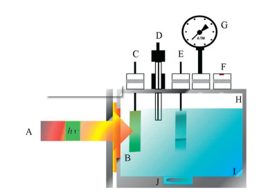
ZIF-8 can also decorate Ti/TiO2 nanotubes for CO2 photoelectrocatalytic reduction under 125 W mercury vapor lamp irradiation [52]. The photocurrent and the value of the solution saturated with CO2 were significantly increased after coating the Ti/TiO2 electrode with ZIF-8. Moreover, spectroscopic and voltammetric measurements confirmed that CO2 formed stable carbamates on the surface of ZIF-8. The photoelectrocatalytic reactor was shown in Fig. 4. At Eapp of +0.1 V, in 0.1 mol/L Na2SO4, CO2 was reduced to form 0.7 mmol/Lmethanol and 10 mmol/L ethanol.

|
Download:
|
| Fig. 4. Schematic diagram of photoreactor: (A) lamp, (B) quartz window, (C) working electrode, (D) reference electrode, (E) counter electrode, (F) septum, (G) manometer, (H) headspace, (I) supporting electrolyte, (J) magnetic bar. Reporduced with permission [52], Copyright 2018, Elsevier. | |
In addition, ZIF-8 derivatives have also been reported to be successfully used in photoelectrocatalytic reactions. Zou et al. prepared ZIF-8-derived carbon-doped ZnO (C-ZnO) with porous structure by two-step calcination of ZIF-8 for photoelectrocatalytic water splitting irradiated by a 300 W Xenon lamp (> 420 nm) [53]. ZIF-8 was synthesized by dropping an aqueous solution of zinc acetate into an ammonia solution of 2-methylimidazole, followed by stirring for 4 h. The prepared ZIF-8 was first calcined at 350 ℃ and then at 400 ℃ to obtain C-ZnO (labeled as ZnO (C350-400)). This two-step calcination method not only successfully doped C into the ZnO crystal lattice, but also maintained the cubic morphology of the ZnO with porous structure compared with the one-step calcination. Compared to ZnO (C450), the absorption edge of ZnO (C350-400) showed a redshift, indicating that the twostep calcined sample had better light absorption than the directly calcined sample. And the photoluminescence (PL) intensity of the two-step calcined sample was lower than that of the directly calcined sample, demonstrating that the former had higher charge separation efficiency. Finally, in the photoelectrochemical water splitting experiments, ZnO (C350-400) exhibited the highest activity with a photocurrent density of 83 μA/cm2 at 1.23 V vs. RHE, which was 4 times higher than that of C450.
Besides, Zn-based MOF ([Zn(bpcda)(bdc)]n, bpcda = N, N'-bis (pyridin-4-ylmethylene) cyclohexane-1, 4-diamine, bdc = benzenedicarboxylic acid) prepared by solvothermal method also exhibited significant photoelectrochemical catalytic activity under simulated AM 1.5 G solar irradiation (100 mW/cm2) [54]. In this Zn-based MOF, the metal center was attached to the bdc anion to generate one-dimensional chains that were connected by bipyridyl bpcda to construct a three-dimensional framework. Characterization demonstrated that [Zn(bpcda)(bdc)]n not only absorbed a long-range of light but also exhibited multiple LUMO/HOMO levels. The presence of metal centers and two different ligands resulted in these multiple absorption bands, promoting photogenerated electronhole separation, thereby increasing the oxygen evolution reaction (OER) activity of [Zn(bpcda)(bdc)]n. The maximum photocurrent density of [Zn(bpcda)(bdc)]n anode exceeded 31 μA/cm2 at 0.9 V (Ag/AgCl/Sat. KCl). In addition, the [Zn(bpcda)(bdc)]n anode exhibited reproducibility throughout the experimental time (more than 12 h), indicating high photoresponse stability and negligible photocorrosion.
3.3. Co-based MOFsCo-based MOF is also considered to be a promising material for photoelectrocatalysis, and it has been extensively studied. For instance, Co-MOF (ZIF-67) was coated on noble metal sensitized semiconductor (ZnO@M, M = Au, Pt, and Ag) for photoelectrochemical water splitting irradiated by a 150 W Xenon lamp (100 mW/cm2) [55]. The prepared ZnO@Au@ZIF-67 had the following advantages: (ⅰ) The narrow bandgap ZIF-67 could enhance effective light response, and its porous structure hardly blocked the light absorption of ZnO@Au. Compared with ZnO and ZnO@Au, the light absorption intensity of ZnO@Au@ZIF-67 increased significantly from the ultraviolet to the visible range. (ⅱ) The photogenerated electrons in the ZIF-67 shell were rapidly transferred to ZnO@Au because the well-contacted ZIF-67/ZnO@Au interface could accelerate charge transfer. Compared with ZnO, the photoluminescence intensity of ZnO@Au was decreased, indicating that Au was favorable for suppressing electron and hole recombination. In addition, after ZIF-67 growth, the photoluminescence intensity was further reduced, demonstrating that ZnO@Au@ZIF-67 can improve the transfer of photoelectron-hole. (ⅲ) The ZIF-67 could serve as a protecting layer to avoid aggregation or leaching of ZnO@Au, which improved the stability of the photoanode. As a result, the photocurrent density of ZnO@Au@ZIF-67 was 1.93 mA/cm2, and the onset potential of ZnO@Au@ZIF-67 displayed a cathodic shift from 0.05 V to -0.1 V. Moreover, this strategy could be extended to the preparation of ZnO@Ag@ZIF-67 and ZnO@Pt@ZIF-67, which also had high photoelectrochemical water splitting activity.
Recently, ZIF-67 was in-situ grown on Fe2O3 for photoelectrocatalytic OER irradiated by a 300 W Xenon lamp (100 mW/cm2) [56]. In the preparation process, a Fe2O3 film was prepared on FTO glass by a simple hydrothermal method. To prepare a Co-modified Fe2O3 film, the synthesized bare Fe2O3 film was spin-coated with a Co(NO3)2 aqueous solution, and then heated. Subsequently, this Co-modified Fe2O3 film was immersed in a 2-methylimidazole solution for a period of time, washed with water, and then dried to obtain an in-situ Co-MOF modified Fe2O3 photoanode (Fe2O3@- Co@MIm). Compared with bare Fe2O3, the Vonset of Fe2O3@Co@- MIm showed a significant cathodic shift (180 mV), indicating that surface treatment with Co-MOF enhanced OER. This enhancement was due to the fact that the porous Co-MOF was rich in Co active sites, which can rapidly transport electrons as a redox medium. In addition, the photocurrent density of optimized Fe2O3@Co@MIm showed a significant increase to 2.0 mA/cm2 at 1.23 V vs. RHE. However, an excessively thick Co-MOF layer weakened the interaction between the Fe2O3 and the electrolyte, thereby suppressing hole transfer and resulting in lower photocurrent density and a higher onset potential.
Co-based MOF (ZIF-9) was also used by Zhao et al. to modify Co3O4 nanowire to construct a biomimetic photoelectrocatalytic interface for photoelectrocatalysis under simulated AM 1.5 G solar irradiation (100 mW/cm2) [57]. Experiments revealed that CO2 can be well adsorbed on the ZIF-9 modified Co3O4 nanowire. Moreover, on this hybrid interface, the CO2 surface concentration increased by 3.44 times compared to that on Co3O4 nanowire. Density functional theory (DFT) showed that ZIF-9 has the ability to activate CO2 molecules by combining Co atoms with O atoms of CO2, leading to a positive shift in the CO2 reduction onset potential on ZIF-9-Co3O4 hybrid compared to Co3O4 nanowire. The photoelectrocatalytic conversion of CO2 to formate was 72.3 μmol L-1 cm-2 h-1, and the liquid product selectivity was close to 100% at a low overpotential (290 mV).
Apart from ZIF-67 and ZIF-9, Co2(benzimidazole)4 was also used to modify BiVO4 photoanode for OER under simulated AM 1.5 G solar irradiation (100 mW/cm2) [58]. Ultrathin CoO sheets were used as the metal source for in-situ preparation of small size CoMOF nanoparticle on BiVO4. The photocurrent density of Co-MOF modified BiVO4 photoanode was 3.1 mA/cm2 at 1.23 V vs. RHE, which was much better than that of BiVO4 photoanode (1.2 mA/cm2). In addition, after the incorporation of Co-MOF, a significant cathodic shift occurred at the onset potential of Co-MOF modified BiVO4, indicating that Co-MOF had OER activity. Highly dispersed and small-sized Co-MOF acted as a cocatalyst to rapidly transfer the photogenerated holes in BiVO4 and enhance the surface reaction kinetics of photoelectrochemical OER. Moreover, Co-MOF with abundant metal sites and porosity displayed high charge separation efficiency (83%), also resulting in boosted OER activity of the Co-MOF modified BiVO4 photoanode. Recently, another Co-based MOF, (Co-MIm) nanosheets were grown on BiVO4 for photoelectrocatalytic overall water splitting [59]. The photocurrent density of BiVO4@Co-MIm at 1.23 V vs. RHE was 3.16 mA/cm2, which was 2.4 times that of BiVO4 photoanode. CoMIm coating caused a 230 mV cathode shift of onset potential, demonstrating that Co-MIm had excellent water oxidation properties. Studies also confirmed that BiVO4@Co-MIm photoanodes had high charge separation efficiency compared with BiVO4 photoanodes. As shown in Fig. 5, the photoelectrocatalytic process of the BiVO4@Co-MIm photoanode was carried out under AM 1.5 G irradiation (100 mW/cm2) using an H-type cell. The oxygen and hydrogen produced after 3 h were 79 μmol and 161 μmol, respectively, which were in accordance with Faraday efficiency of 92.3% and 91.8%, respectively. During this process, BiVO4 was excited and produced photogenerated electron-hole pairs under illumination. Co3+ of Co-MIm was first oxidized by holes to Co4+. Then, Co4+ was reduced to Co2+ in the water while generating oxygen. Subsequently, Co2+ was oxidized by holes to Co3+. At the same time, electrons were transferred to the cathode for hydrogen production.

|
Download:
|
| Fig. 5. The proposed photoelectrocatalytic process on the BiVO4@Co-MIm anode. Reporduced with permission [59], Copyright 2019, Elsevier. | |
Co-MOF derivatives were also reported as photoelectrocatalysts. The ZIF-67-derived Co3C/TiO2 heterostructure was constructed by the hydrothermal method for photoelectrocatalytic water oxidation irradiated by a 150 W Xenon lamp [60]. First, a layer of TiO2 was coated on the Cu2O template by hydrothermal. Then, the synthesized TiO2/Cu2O was added to a solution of Co(NO3)2 and 2-methylimidazole. Under electrostatic attraction, ZIF- 67 was deposited on TiO2/Cu2O. Finally, the synthesized ZIF-67/TiO2/Cu2O was calcined under argon to obtain ZIF-67-derived Co3C/TiO2 nanocage. ZIF-67-derived Co3C could enhance light capture and promote water oxidation kinetics. At the same time, the type Ⅱ heterojunction formed by TiO2 and Co3C enhanced the separation of photogenerated electron-hole. Moreover, as a cocatalyst, ZIF-67-derived Co3C could oxidize OH- to O2 to fast consume the trapped photogenerated holes, thereby significantly suppressing the recombination of surface carriers. As a result, the ZIF-67-derived Co3C/TiO2 photoanode significantly increased the photoelectrocatalytic water oxidation activity. The optimized ZIF- 67-derived Co3C/TiO2 anode had a photocurrent density of 2.6 mA/cm2 and a charge separation efficiency of 92.6%, which was 201% and 152% higher than that of TiO2, respectively. Besides, ZIF-67 derived Co3O4 coated TiO2 nanorod arrays on Si were constructed as photoanode for efficient photoelectrochemical water oxidation under simulated AM 1.5 G solar irradiation (100 mW/cm2) [61]. This Co3O4/TiO2/Si ternary heterojunction could promote carrier separation. The CB and VB potentials of Si were higher than that of TiO2, and the photogenerated electrons from the CB of TiO2 were rapidly transferred to the VB of Si, thereby effectively separating the electrons from TiO2 and the holes from Si. In addition, because of the large specific surface area and porous channel structure, MOFs-derived Co3O4 significantly enhanced the photoresponse and water oxidation kinetics of Co3O4/TiO2/Si. Particularly, the onset potential of TiO2/FTO was 0.48 V vs. RHE, and the photocurrent density of TiO2/FTO was 0.83 mA/cm2 at 1.23 V vs. RHE under illumination. When TiO2/FTO was coupled with Co3O4, the onset potential shifted to 0.43 V (vs. RHE), and the photocurrent density increased to 2.00 mA/cm2 at 1.23 V vs. RHE. After incorporation of Si, the synergistic effect of Co3O4/TiO2/Si anode resulted in a photocurrent density of 2.71 mA/cm2 and the light conversion efficiency was greatly increased to 0.54%.
Very recently, Gimenez et al. developed a simple strategy to modify BiVO4-based photoanode with a porous CoOx cocatalyst for photoelectrocatalytic water splitting irradiated by a 300 W Xenon lamp (100 mW/cm2) [62]. The surface of BiVO4 was first modified with benzene-1, 3, 5-tricarboxylic acid, and then ZIF-67 was assembled by simply mixing 2-methylimidazole and cobalt nitrate in methanol. By this method, uniform growth and strong adhesion of MOF particles were produced on the surface of BiVO4 (labeled as BiVO4-ZIF-67). Subsequently, the MOF particles were converted to porous CoOx cocatalysts (labeled as BiVO4-CoOx) by calcining the BiVO4-ZIF-67 sample in air. Benefited from the high surface area, this porous CoOx cocatalyst exposed sufficient catalytically active sites for OER. In addition, MOF-converted CoOx cocatalyst significantly enhanced light scattering and bandgap absorption on BiVO4, which facilitated light trapping. Therefore, water oxidation kinetics could be significantly accelerated. Photoelectrochemical characterization of the BiVO4-CoOx photoanode showed a significant increase in catalytic performance compared with the BiVO4 electrode (about 4 times higher photocurrent and 300 mV cathode offset of the catalytic onset potential).
3.4. Fe-based MOFsFe-based MOFs attract a lot of attention because they have strong light absorption and iron is an earth-abundant element. Jiao et al. used Fe-based MOF (MIL-100(Fe)) to modify nanoporous Fe/W co-doped BiVO4 photoelectrodes for photoelectrochemical water splitting irradiated by a 300 W Xenon lamp (100 mW/cm2) [63]. The distribution of MIL-100(Fe) on the Fe/W codoped BiVO4 photoanode was confirmed by scanning electron microscopy (SEM) images. Since the bandgap of MIL-100(Fe) was about 2 eV, the absorption edge was greatly red-shifted on the Fe/W co-doped BiVO4 film after MIL-100(Fe) decoration. The photocurrent density of MIL-100(Fe) modified Fe/W co-doped BiVO4 was 2.76 mA/cm2, which was 14 times that of BiVO4. Here, MIL-100(Fe) was used as a cocatalyst because of its low photoelectrochemical performance, small amount, and the significant effect of Efb on Fe/W co-doped BiVO4. In this case, electrons and holes generated from Fe/W co-doping BiVO4 can be rapidly separated in the interface of MIL-100(Fe) and Fe/W co-doped BiVO4. The electrons were transported to the counter electrode under bias for reduction reaction, and the holes are rapidly migrated to MIL-100(Fe) for the oxidation reaction. Additional, MIL-100(Fe) possessed a porous structure that was advantageous for its contact with the electrolyte, which may also contribute to an increase in photoelectrochemical activity.
MIL-53(Fe) was used as a cocatalyst to efficiently promote hole transport, significantly improving the photoelectrocatalytic activity of Mo-doped BiVO4 photoanodes for water oxidation under simulated AM 1.5 G solar irradiation (100 mW/cm2) [64]. Modoped BiVO4-MIL-53(Fe) (FMBV) photoanode was prepared by simply coating a Mo-doped BiVO4 film on FTO and then spincoating a MIL-53(Fe) co-catalyst. By doping Mo6+, the charge transport properties of BiVO4 could be enhanced, thereby improving the water oxidation efficiency of Mo-doped BiVO4. Moreover, in the presence of MIL-53(Fe), not only the charge carrier density was increased but also the photogenerated electron-hole separation was accelerated. Specifically, after the spin coating of MIL-53(Fe), FMBV showed a significantly improved photoresponse. The photocurrent density of FMBV was 2.2 mA/cm2 at 1.23 V vs. RHE, while that of pure BiVO4 was only 0.57 mA/cm2. A possible mechanism was that the VB electrons of Mo-doped BiVO4 were excited to CB under illumination and then transferred to the FTO. At the same time, photogenerated holes were transported to MIL-53(Fe). MIL-53(Fe) could rapidly transfer the holes from Modoped BiVO4 to the electrolyte due to the three-dimensional framework structure of MIL-53(Fe). The junction formed between MIL-53(Fe) and Mo-doped BiVO4 further suppressed photogenerated electrons and photogenerated holes recombination, thereby improving the photoelectrocatalytic performance.
Recently, Chen et al. prepared an ultrathin Fe-based MOF (NH2- MIL-101(Fe)) film coated Fe2O3 nanorod array anode for effective photoelectrocatalytic water oxidation [65]. First, a Ti-doped Fe2O3 nanorod array was vertically grown on FTO glass. After modification with polyvinyl pyrrolidone (PVP), the NH2-MIL-101(Fe) shell was prepared by solvothermal. In this preparation process, Ti dopants were intended to increase the conductivity of Fe2O3. Besides, the PVP was used as a bridging agent because it could be easily adsorbed on Fe2O3 and then provided a nucleation site for the growth of MOF. Under simulated AM 1.5 G solar irradiation (100 mW/cm2), the photoanode of the Ti-doped Fe2O3 nanorods had a photocurrent density of 0.98 mA/cm2 at 1.23 V vs. RHE. After modification by NH2-MIL-101(Fe), the photocurrent density was raised to 2.27 mA/cm2. And the Ti-doped Fe2O3/NH2-MIL-101(Fe) core/shell anode displayed the highest photoelectrocatalytic water oxidation performance. Since the Fe2O3 photoanode was greatly affected by poor conductivity and short hole diffusion length, the charge separation efficiency of Ti-doped Fe2O3/NH2-MIL-101(Fe) electrodes was enhanced because of the type Ⅱ heterostructure formed. Under light irradiation, the photogenerated electrons were transferred from the LUMO of NH2-MIL-101(Fe) to the CB of Tidoped Fe2O3, and the photogenerated holes migrated inversely to the HOMO of NH2-MIL-101(Fe), promoting rapid separation of photogenerated electrons and holes. In addition, efficient charge separation would cause more photogenerated holes to accumulate on the photocatalyst surface, resulting in superior oxidizing power.
3.5. Cu-based MOFsCu-based MOFs have been explored in depth for photoelectrocatalysis because Copper is an earth-abundant element and relatively low in cost. As a typical Cu-based MOF, HKUST-1 (Cu3(BTC)2, BTC = benzene-1, 3, 5-tricarboxylate)-reduced graphite oxide (rGO)/Pt-Cu foam was prepared as a cathode catalyst for photoelectrochemical reduction of CO2 irradiated by a 300 W Xenon lamp [66]. The bonding of rGO to Cu3(BTC)2 not only produced more active sites but also promoted the faster transfer of electrons on the catalyst surface. The CO2 conversion rate reached 3256 nmol h-1 cm-2, which was much higher than pure Cu3(BTC)2 as a cathode catalyst. When -2 V voltage was applied to this photoelectrochemical system, the liquid product had a selectivity to alcohol of up to 94.6%. The Pt nanoparticles on the Cu foam and rGO in the catalyst first transferred electrons to CO2 to produce C1 intermediate. Due to the good selectivity of Pt for CO production, more CO was produced than other C1 organics. Then, the porous structure of Cu3(BTC)2 promoted C—C bonding to produce alcohol.
In addition, HKUST-1 was also reported to be coated on Cu2O cathode to inhibit photocorrosion and provide reactive sites for the reduction of CO2 under simulated AM 1.5 G solar irradiation (100 mW/cm2) [67]. This photocathode was formed by depositing Cu2O film on indium tin oxide (ITO) glass and then growing Cu3(BTC)2 by a solution-phase reaction using Cu2O as a copper source. Various characterizations verified that the Cu3(BTC)2 coating not only does not change the bandgap of Cu2O but also significantly promotes photogenerated charge separation and transport in Cu2O. Photoelectrocatalytic reduction of CO2 was completed in a threeelectrode quartz photoelectrocatalytic (PEC) cell containing tetrabutylammonium hexafluorophosphate (TBAPF6) in CO2 saturated acetonitrile as an electrolyte, as shown in Fig. 6. The 13C isotope labeling experiment confirmed that only CO was produced by reduction, and there were no liquid hydrocarbons and other gaseous products. In the absence of light, the CO yield increased with the applied potential, but the yield of Cu3(BTC)2/Cu2O was 2 times higher than that of Cu2O. When the PEC cell was irradiated with visible light, the yield of Cu3(BTC)2/Cu2O was significantly improved about 4 times as compared with that of Cu2O.

|
Download:
|
| Fig. 6. Illustration for photoelectrochemical CO2 reduction utilizing Cu3(BTC)2/Cu2O cathode. Reporduced with permission [67], Copyright 2019, American Chemical Society. | |
Mixed metal-based MOFs were defined by Chen et al. [68] in 2011 and have been explored for efficient photoelectrocatalysis. For example, Cui et al. fabricated a ternary semiconductor that coated ZIF-8/67 on ZnO nanorod arrays (NAs), which exhibited high-efficiency photoelectrocatalytic water splitting activity under simulated AM 1.5 G solar irradiation (100 mW/cm2) [69]. ZnO-NAs were synthesized on FTO, then added with Co(NO3)2 and 2- methylimidazole for hydrothermal reaction to obtain ZnO@ZIF-8/67-NAs. ZnO@ZIF-8/67-NAs exhibited a strong visible light response, while the absorption edge of ZnO was located near 390 nm due to its wide bandgap. In addition, the one-dimensional structure of ZnO NAs was also beneficial to the rapid transmission of electrons. Under visible light irradiation, the photogenerated electrons generated by ZnO@ZIF-8/67-NAs were transported to the Pt electrode by an external circuit to generate hydrogen, and the photogenerated holes reacted with water to generate oxygen. As a result, the photocurrent density of the ZnO@ZIF-8/67-NAs anode at 1.23 V vs. RHE was 0.11 mA/cm2, while that of the ZnO-NAs was only 0.012 mA/cm2.
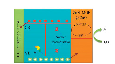
Similarly, mixed metal-based MOF (ZnNi-MOF) was successfully coated on the surface of the ZnO nanowire array for photoelectrochemical reactions under simulated AM 1.5 G solar irradiation [70]. First, ZnO nanowire arrays were synthesized by the hydrothermal method. Then, 1, 4-phthalic acid was added to form MOF-5. Here, ZnO not only provided Zn2+ ions for synthesizing MOF-5 but also served as a template. Finally, part of the Zn2+ was replaced by Ni2+ through ion exchange, thereby obtaining a ZnNi-MOF@ZnO nanowire array. In the dark conditions, the current densities of the three photoanodes (ZnO, MOF-5@ZnO, and ZnNi-MOF@ZnO nanowire arrays) were very low and all about 0.04 mA/cm2 at 1.2 V vs. RHE. Under illumination, the photocurrent densities of ZnO, MOF-5@ZnO, and ZnNi-MOF@ZnO at 1.20 V vs. RHE were 0.6, 0.88, and 1.40 mA/cm2, respectively, showing a considerable enhancement in photocurrent. The possible mechanism of photoelectrocatalysis of ZnNi-MOF@ZnO was shown in Fig. 7. The photogenerated electrons generated in ZnO by illumination moved to the substrate and then to the counter electrode for producing hydrogen. At the same time, the photogenerated holes generated in ZnO moved to the ZnNi-MOF, and then oxidize Ni2+ to Ni3+/Ni4+. Subsequently, the Ni3+/Ni4+ interacted with nearby water to produce oxygen.

|
Download:
|
| Fig. 7. The possible mechanism of photoelectrocatalysis of ZnNi-MOF@ZnO. Reporduced with permission [70], Copyright 2019, Elsevier. | |
Besides, mixed metal-based MOF derivatives can also act as highly efficient photoelectrocatalyst due to their unique structure and the synergistic effect of two uniformly distributed metals. An example of a mixed metal-based MOF derivative was reported by Dou's group [71]. In this article, mixed metal-based MOF (ZIF-8/67) was coated onto ZnO and then sulfurized to prepare ZnO@ZnS/CoS for photoelectrocatalytic water oxidation irradiated by a 300 W Xenon lamp (100 mW/cm2). Due to the framework structure of the original ZIFs, the surface area of ZnO@ZnS/CoS was 191.8 m2/g, which was much larger than that of ZnO powder (15.1 m2/g). And the pore size was mainly distributed between 2 nm and 5 nm, indicating that ZnO@ZnS/CoS possessed a hierarchical microporous and mesoporous structure. For ZnO and ZnO@ZnS/CoS, the fluorescence lifetime values were measured to be 3.03 and 7.06 ns, respectively, showing that the addition of ZIFs derivatives favored charge transfer and surface reactions. The onset potential of ZnO@ZnS/CoS showed a significant negative shift from -0.20 V to -0.35 V, and the photocurrent density was 2.46 mA/cm2 at 0.6 V vs. SCE, which was 5.1 times that of ZnO. The improved photoelectrocatalytic activity was due to the unique structure imparting rich exposure sites and efficient light capture to ZnO@ZnS/CoS photoanode. In addition, the cocatalyst CoS could accept photogenerated holes to accelerate rapid hole transport and water oxidation reaction, while photogenerated electrons were quickly guided to the counter electrode through the ZnO rod, effectively suppressing electron-hole recombination.
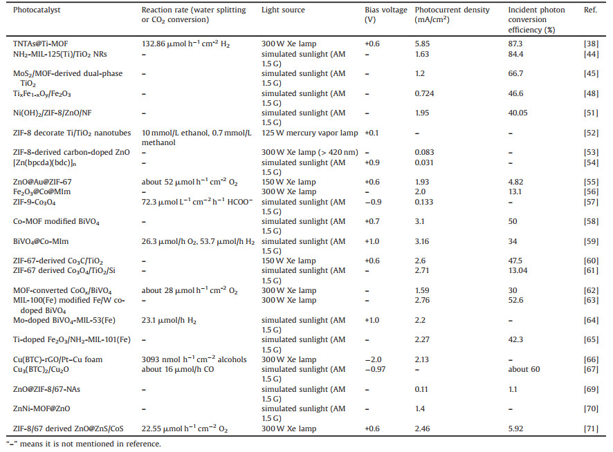
3.7. Comparison of MOFs photoelectrodes with other photoelectrodesTable 1 summarizes the photoelectrocatalysis based on MOFs materials in this review, and Table S1 (Supporting information) lists recently reported photocatalysis based on other heterogeneous materials. It can be seen that MOFs materials exhibit comparable or better performance in photoelectrocatalytic water splitting and CO2 conversion compared to other materials.
|
|
Table 1 Overview of photoelectrocatalysis based on MOFs. |
In summary, recent studies have demonstrated that photoelectrocatalysis has great potential for application in many fields including CO2 conversion, water splitting for hydrogen evolution reaction (HER), and OER. Photoelectrocatalysis, coupled with heterogeneous photocatalysis and electrocatalysis, possesses the advantages of both methods. Various researches have shown that photoelectrocatalysis has better catalytic performance under similar conditions than photocatalysis and electrolysis. Since the anode material is a key component in the photoelectrocatalytic device, enormous efforts have been made to develop photoelectrocatalytic materials that achieve excellent catalytic performance under mild conditions. Among these photoelectrocatalysts, the emerging MOFs have attracted much attention because of their porosity, large surface area, and tunable structure. MOFs can form heterojunctions with other semiconductor materials and can be used as co-catalysts for photoelectrocatalytic processes. Moreover, MOFs derivatives can also be used to construct photoelectrodes due to their inherited porous structures from the pristine MOFs. In photocatalytic processes, MOFs photoelectrodes play triple roles: (ⅰ) promoting charge separation and transfer of electrons to the active sites, (ⅱ) improving photoelectrode stability and protecting photoelectrode from photocorrosion, and (ⅲ) providing more active sites to catalyze CO2 conversion and water splitting. There is no doubt that the photoelectrodes containing various metal-based MOF materials exhibit high activity.
However, in order to finally realize the practical application of this technology, there are still a lot of challenges for MOFs in photoelectrocatalysis. First, the bandgap of MOFs determines the range of light absorption. For MOFs with a narrower bandgap, a stronger visible light response can be expected. Therefore, it is feasible to decrease the bandgap of MOFs by various methods such as modifying MOFs and developing new MOFs. In addition, the transmission speed of photogenerated electrons and photogenerated holes is also critical to the photoelectrode material. Constructing a rational heterostructure consisting of MOFs with other semiconductor materials is essential to promote charge separation. Moreover, the stability of the photoelectrode material must be high for long-term photoelectrocatalytic reactions. Therefore, because the stability of MOFs is usually limited, improving its stability is also an important research direction. Apart from these, the mechanism of photoelectrocatalytic reactions has not yet been fully elucidated, and more research efforts are needed. Combining experimental results with theoretical calculation (e.g., density functional theory calculation) to explore photoelectrocatalytic reaction mechanisms is a promising approach. Although there is still a lot of work to be done, MOFs are still good candidates for photoelectrocatalytic reactions, and the prospects for this field are bright.
Declaration of competing interestThe authors declare that no conflict of interest exits in the submission of this manuscript, and the manuscript is approved by all authors for publication.
AcknowledgmentsThis work was supported by the Natural Science Foundation of Jiangsu Province of China (Nos. BK20160430, BK20181070), the National Natural Science Foundation of China (No. 51808250), the Project Funded by China Postdoctoral Science Foundation (Nos. 2016M591757, 2017M610336), and the Jiangsu Planned Projects for Postdoctoral Research Funds of China (No. 1601179C).
Appendix A. Supplementary dataSupplementarymaterial related to this article can befound, in the online version, at doi: https://doi.org/10.1016/j.cclet.2019.12.015.
| [1] |
Y. Wang, H. Suzuki, J. Xie, et al., Chem. Rev. 118 (2018) 5201-5241. DOI:10.1021/acs.chemrev.7b00286 |
| [2] |
Z. Wang, C. Li, K. Domen, Chem. Soc. Rev. 48 (2019) 2109-2125. DOI:10.1039/C8CS00542G |
| [3] |
W. Zhao, Y. Feng, H. Huang, et al., Appl. Catal. B 245 (2019) 448-458. DOI:10.1016/j.apcatb.2019.01.001 |
| [4] |
M. Volokh, G. Peng, J. Barrio, M. Shalom, Angew. Chem. Int. Ed. 58 (2019) 6138-6151. DOI:10.1002/anie.201806514 |
| [5] |
A. Naldoni, M. Altomare, G. Zoppellaro, et al., ACS Catal. 9 (2019) 345-364. DOI:10.1021/acscatal.8b04068 |
| [6] |
J. Liang, Y.B. Huang, R. Cao, Coord. Chem. Rev. 378 (2019) 32-65. DOI:10.1016/j.ccr.2017.11.013 |
| [7] |
Y. Zhao, Y. Zhao, R. Shi, et al., Adv. Mater. 31 (2019) 1806482. DOI:10.1002/adma.201806482 |
| [8] |
F. Chen, H. Huang, L. Ye, et al., Adv. Funct. Mater. 28 (2018) 1804284. DOI:10.1002/adfm.201804284 |
| [9] |
I. Roger, M.A. Shipman, M.D. Symes, Int. Rev. Chem. Eng. 1 (2017) 0003. |
| [10] |
C. Ding, J. Shi, Z. Wang, C. Li, ACS Catal. 7 (2017) 675-688. DOI:10.1021/acscatal.6b03107 |
| [11] |
H. Wang, Y. Liang, L. Liu, J. Hu, W. Cui, J. Hazard. Mater. 344 (2018) 369-380. DOI:10.1016/j.jhazmat.2017.10.044 |
| [12] |
T. Yao, X. An, H. Han, J.Q. Chen, C. Li, Adv. Energy Mater. 8 (2018) 1800210. DOI:10.1002/aenm.201800210 |
| [13] |
M. Faraji, M. Yousefi, S. Yousefzadeh, et al., Energy Environ. Sci. 12 (2019) 59-95. DOI:10.1039/C8EE00886H |
| [14] |
X. Cao, X. Zang, X. Zhou, M. Chen, Y. Ding, Chin. Chem. Lett. 29 (2018) 811-814. DOI:10.1016/j.cclet.2017.12.010 |
| [15] |
W. Zhao, J. Li, B. Dai, et al., Chem. Eng. J. 369 (2019) 716-725. DOI:10.1016/j.cej.2019.03.115 |
| [16] |
W. Zhao, X. Tu, X. Wang, et al., Chem. Eng. J. 361 (2019) 1173-1181. DOI:10.1016/j.cej.2018.12.120 |
| [17] |
A. Fujishima, K. Honda, Nature 238 (1972) 37-38. DOI:10.1038/238037a0 |
| [18] |
Y. Feng, H. Cheng, J. Han, et al., Chin. Chem. Lett. 28 (2017) 2254-2258. DOI:10.1016/j.cclet.2017.10.025 |
| [19] |
K.K. Paul, N. Sreekanth, R.K. Biroju, et al., J. Mater. Chem. A 6 (2018) 22681-22696. DOI:10.1039/C8TA06783J |
| [20] |
H. Zhang, G. Chen, D.W. Bahnemann, J. Mater. Chem. 19 (2009) 5089-5121. DOI:10.1039/b821991e |
| [21] |
Y. Zhang, X. Xiong, Y. Han, et al., Chemosphere 88 (2012) 145-154. DOI:10.1016/j.chemosphere.2012.03.020 |
| [22] |
T. Zhu, M.N. Chong, E.S. Chan, ChemSusChem 7 (2014) 2974-2997. DOI:10.1002/cssc.201402089 |
| [23] |
M. Bonomo, D. Dini, F. Decker, Front. Chem. 6 (2018) 601. DOI:10.3389/fchem.2018.00601 |
| [24] |
A. García, C. Fernandez-Blanco, J.R. Herance, J. Albero, H. García, J. Mater. Chem. A:Mater. Energy Sustain. 5 (2017) 16522-16536. DOI:10.1039/C7TA04045H |
| [25] |
J. Qiu, X. Zhang, Y. Feng, et al., Appl. Catal. B 231 (2018) 317-342. DOI:10.1016/j.apcatb.2018.03.039 |
| [26] |
S. Wang, S. Hou, C. Wu, Y. Zhao, X. Ma, Chin. Chem. Lett. 30 (2019) 398-402. DOI:10.1016/j.cclet.2018.06.021 |
| [27] |
Z. Han, W. Shi, P. Cheng, Chin. Chem. Lett. 29 (2018) 819-822. DOI:10.1016/j.cclet.2017.09.050 |
| [28] |
W. Li, Prog. Mater. Sci. 100 (2019) 21-63. DOI:10.1016/j.pmatsci.2018.09.003 |
| [29] |
Y. Yang, Z. Zeng, C. Zhang, et al., Chem. Eng. J. 349 (2018) 808-821. DOI:10.1016/j.cej.2018.05.093 |
| [30] |
M. Ji, Z. Zhang, J. Xia, et al., Chin. Chem. Lett. 29 (2018) 805-810. DOI:10.1016/j.cclet.2018.05.002 |
| [31] |
E. Zarei, R. Ojani, J. Solid State Electrochem. 21 (2016) 305-336. |
| [32] |
H. Zhang, J. Li, Q. Tan, et al., Chem.-Eur. J. 24 (2018) 18137-18157. DOI:10.1002/chem.201803083 |
| [33] |
H. Rao, L.C. Schmidt, J. Bonin, M. Robert, Nature 548 (2017) 74-77. DOI:10.1038/nature23016 |
| [34] |
T. Ouyang, H.H. Huang, J.W. Wang, D.C. Zhong, T.B. Lu, Angew. Chem. Int. Ed. 56 (2017) 738-743. DOI:10.1002/anie.201610607 |
| [35] |
N. Wu, Nanoscale 10 (2018) 2679-2696. DOI:10.1039/C7NR08487K |
| [36] |
M.Z. Iqbal, S. Siddique, Int. J. Hydrogen Energy 43 (2018) 21502-21523. DOI:10.1016/j.ijhydene.2018.09.157 |
| [37] |
Z. Zeng, Y.B. Li, S. Chen, P. Chen, F.X. Xiao, J. Mater. Chem. A 6 (2018) 11154-11162. DOI:10.1039/C8TA02802H |
| [38] |
H. Song, Z. Sun, Y. Xu, et al., Sep. Purif. Technol. 228 (2019) 115764. DOI:10.1016/j.seppur.2019.115764 |
| [39] |
H.C. Li, Y.J. Zhang, X. Hu, et al., Adv. Energy Mater. 8 (2018) 1702734. DOI:10.1002/aenm.201702734 |
| [40] |
J. Wang, C. Xue, W. Yao, et al., Appl. Catal. B 250 (2019) 369-381. DOI:10.1016/j.apcatb.2019.03.002 |
| [41] |
F.Z. Song, Q.L. Zhu, X. Yang, et al., Adv. Energy Mater. 8 (2018) 1770139. DOI:10.1002/aenm.201870006 |
| [42] |
M. Ge, J. Cai, J. Iocozzia, et al., Int. J. Hydrogen Energy 42 (2017) 8418-8449. DOI:10.1016/j.ijhydene.2016.12.052 |
| [43] |
Z. Wei, F. Liang, Y. Liu, et al., Appl. Catal. B 201 (2017) 600-606. DOI:10.1016/j.apcatb.2016.09.003 |
| [44] |
J.W. Yoon, D.H. Kim, J.H. Kim, H.W. Jang, J.H. Lee, Appl. Catal. B 244 (2019) 511-518. DOI:10.1016/j.apcatb.2018.11.057 |
| [45] |
R. Tang, R. Yin, S. Zhou, et al., J. Mater. Chem. A 5 (2017) 4962-4971. DOI:10.1039/C6TA10511D |
| [46] |
S. Kment, F. Riboni, S. Pausova, et al., Chem. Soc. Rev. 46 (2017) 3716-3769. DOI:10.1039/C6CS00015K |
| [47] |
R. Franking, L. Li, M.A. Lukowski, et al., Energy Environ. Sci. 6 (2013) 500-512. DOI:10.1039/C2EE23837C |
| [48] |
C.H. Li, C.L. Huang, X.F. Chuah, et al., Chem. Eng. J. 361 (2019) 660-670. DOI:10.1016/j.cej.2018.12.097 |
| [49] |
M. Shao, F. Ning, M. Wei, D.G. Evans, X. Duan, Adv. Funct. Mater. 24 (2014) 580-586. DOI:10.1002/adfm.201301889 |
| [50] |
M. Li, K. Chang, T. Wang, et al., J. Mater. Chem. A 3 (2015) 13731-13737. DOI:10.1039/C5TA02901E |
| [51] |
X. Li, S. Liu, K. Fan, et al., Adv. Energy Mater. 8 (2018) 1800101. DOI:10.1002/aenm.201800101 |
| [52] |
J.C. Cardoso, S. Stulp, J.F. de Brito, et al., Appl. Catal. B 225 (2018) 563-573. DOI:10.1016/j.apcatb.2017.12.013 |
| [53] |
L. Pan, T. Muhammad, L. Ma, et al., Appl. Catal. B 189 (2016) 181-191. DOI:10.1016/j.apcatb.2016.02.066 |
| [54] |
M. Altaf, M. Sohail, M. Mansha, et al., ChemSusChem 11 (2018) 542-546. DOI:10.1002/cssc.201702122 |
| [55] |
Y. Dou, J. Zhou, A. Zhou, J.R. Li, Z. Nie, J. Mater. Chem. A 5 (2017) 19491-19498. DOI:10.1039/C7TA06443H |
| [56] |
Q. Zhang, H. Wang, Y. Dong, et al., Sol. Energy 171 (2018) 388-396. DOI:10.1016/j.solener.2018.06.086 |
| [57] |
Q. Shen, X. Huang, J. Liu, C. Guo, G. Zhao, Appl. Catal. B 201 (2017) 70-76. DOI:10.1016/j.apcatb.2016.08.008 |
| [58] |
W. Zhang, R. Li, X. Zhao, et al., ChemSusChem 11 (2018) 2710-2716. DOI:10.1002/cssc.201801162 |
| [59] |
S. Zhou, P. Yue, J. Huang, et al., Chem. Eng. J. 371 (2019) 885-892. DOI:10.1016/j.cej.2019.04.124 |
| [60] |
R. Tang, S. Zhou, L. Zhang, L. Yin, Adv. Funct. Mater. 28 (2018) 1706154. DOI:10.1002/adfm.201706154 |
| [61] |
R. Tang, S. Zhou, Z. Yuan, L. Yin, Adv. Funct. Mater. 27 (2017) 1701102. DOI:10.1002/adfm.201701102 |
| [62] |
D. Cardenas-Morcoso, R. Ifraemov, M. García-Tecedor, et al., J. Mater. Chem. A 7 (2019) 11143-11149. DOI:10.1039/C9TA01559K |
| [63] |
Z. Jiao, J. Zheng, C. Feng, et al., ChemSusChem 9 (2016) 2824-2831. DOI:10.1002/cssc.201600761 |
| [64] |
B. Zhang, G. Dong, L. Wang, et al., Catal. Sci. Technol. 7 (2017) 4971-4976. DOI:10.1039/C7CY01765K |
| [65] |
Y.J. Dong, J.F. Liao, Z.C. Kong, et al., Appl. Catal. B 237 (2018) 9-17. DOI:10.1016/j.apcatb.2018.05.059 |
| [66] |
J. Cheng, X. Xuan, X. Yang, J. Zhou, K. Cen, RSC Adv. 8 (2018) 32296-32303. DOI:10.1039/C8RA05964K |
| [67] |
X. Deng, R. Li, S. Wu, et al., J. Am. Chem. Soc. 141 (2019) 10924-10929. DOI:10.1021/jacs.9b06239 |
| [68] |
M.C. Das, S. Xiang, Z. Zhang, B. Chen, Angew. Chem. 50 (2011) 10510-10520. DOI:10.1002/anie.201101534 |
| [69] |
G. Jia, L. Liu, L. Zhang, et al., Appl. Surf. Sci. 448 (2018) 254-260. DOI:10.1016/j.apsusc.2018.04.102 |
| [70] |
Z. Peng, S.C. Abbas, J. Lv, et al., Int. J. Hydrogen Energy 44 (2019) 2446-2453. DOI:10.1016/j.ijhydene.2018.12.064 |
| [71] |
J. Zhou, A. Zhou, L. Shu, et al., Appl. Catal. B 226 (2018) 421-428. DOI:10.1016/j.apcatb.2017.12.065 |