 2020, Vol. 31


b Jiangxi Key Laboratory of Organic Chemistry, Jiangxi Science and Technology Normal University, Nanchang 330013, China;
c Materials Science and Technology Program, College of Arts and Sciences, Qatar University, Doha PO Box 2713, Qatar;
d State Key Laboratory for Modification of Chemical Fibers and Polymer Materials, College of Materials Science and Engineering, Donghua University, Shanghai 201620, China
In recent years, more and more severe effects of water pollution to the environment and human health have aroused the extensive attention [1]. Among all the pollutants in wastewater, the dyestuff organics discharged from printing and dyeing industries are considered to be the most refractory ones, exhibiting the characteristics of high toxicity, potential carcinogenicity and difficult degradation [2, 3]. Therefore, a great number of methodologies, such as advanced oxidation processes [4], enzymatic degradation [5], photocatalytic degradation [2, 4, 6, 7], have been developed to reduce such environmental organic hazards. Compared to other methods for eliminating organic pollutants in wastewater, the photocatalytic degradation pathway possesses many attractive advantages including facile operations, low cost and good sustainability, which is highlighted as one of the most promising and environmental-friendly techniques in handling the increasing water pollutants under the irradiation of ultraviolet light or even visible light [2, 4, 6, 8]. Titanium dioxide (TiO2), as a wide-band-gap semiconducting metal oxide (band gap energy of 3.0–3.2 eV), is widely used in the fields of energy storage [9, 10] and photocatalysis [11-14], mainly due to its intrinsic properties of high photocatalytic efficiency, good chemical stability, low cost and nontoxicity to environment. However, one of the most prominent limits of pure TiO2 photocatalysts is the relatively low utilization of visible light because of their wide band gap and the quick recombination of photogenerated electron-hole pairs, which are produced by exciting the valence band electrons of TiO2 into the conduction band by absorption of ultraviolet light. Therefore, in order to enhance the photocatalytic activity of TiO2 under visible light irradiation, a large number of modification strategies have been extensively explored, such as decoration with noble metals (Au, Pt, Pd, etc.) [12, 13, 15-19], doping with nonmetals (C, N, F, S, B, etc.) [20, 21], mixing two TiO2 phases among anatase, rutile and brookite [14], creation of amorphous peroxoTiO2, etc. [22]. Besides, the design of functional photocatalysts with suitable morphologies and large surface area, such as core-shell or yolk-shell nanostructures [12, 17, 23], nanofibers [14], mesoporous structures [15, 18], hollow thin sheets [24], hollow spheres [25, 26], nanotubes [16] and so on, is another strategy to precisely adjust the migration distance of electrons and holes, which can distinctly improve the photocatalytic efficiency. Thus, it is acceptably recognized that a high-performance photocatalyst used under visible light can be rationally synthesized through combining more than one methodology described above.
Although the nanoscale functional photocatalysts based on TiO2 show the promising catalytic efficiency in degradation of organics under visible light irradiation, they still suffer the unavoidable drawbacks of difficult separation and recycling from the heterogeneous catalysis systems [17]. In past decades, magnetite (Fe3O4) nanoparticles have attracted a great deal of interest because of their super paramagnetic property that is beneficial to their recovery usage under an external magnetic field [27]. Core-shell microspheres consisting of magnetic core and mesoporous outer shell are being developed as an important kind of recyclable composite heterogeneous catalysts [28]. However, the magnetic photocatalysts synthesized by directly coating TiO2 onto magnetite particles showed a decreased photoactivity, due to an increase of electron-hole recombination caused by the unfavorable heterojunction between TiO2 shells and iron oxide cores [26]. The insulator polyelectrolytes were found to act as the corrosion protective membrane and prohibit the negative influence of iron oxide on photocatalysis [29]. In a photocatalyst of core-shell Fe3O4/ SiO2/polythiophene submicron composite, the specific semiconductor/insulator/semiconductor structure was highlighted to be helpful for the separation of photo-electrons and holes due to the introduction of SiO2 as the insulating shell, and the catalytic efficiency of methyl orange photodegradation was greatly enhanced [23], but the UV light irradiation and the oxidizing agent of H2O2 were still needed for the catalytic reaction.
Herein, we reported the photocatalytic performance of magnetic core-shell oxygen-deficient titania microspheres (Fe3O4@SiO2@Pt/mTiO2-x) for the first time, which were obtained by a simple stepwise sol-gel coating strategy and further modified with Pt nanoparticles. The unique core-shell structure of magnetic Fe3O4 cores, nonporous SiO2 insulating layers and oxygen-deficient mesoporous anatase TiO2-x shells containing highly dispersed Pt nanoparticles endows the catalyst with significantly increased photocatalytic activity under visible light irradiation and superior recyclability, when used in photodegradation of organic pollutants and dyes (e.g., RhB).
Scheme 1 illustrates the synthesis strategy of core-shell structured Fe3O4@SiO2@Pt/mTiO2-x microspheres. Firstly, using the classical Stöber method, uniform nonporous SiO2 was deposited on magnetic Fe3O4 nanoparticles to obtain the coreshell Fe3O4@SiO2 microspheres through the controlled hydrolysis and condensation of TEOS in ethanol/water/NH4OH mixed solution. Secondly, a compact amorphous TiO2 layer was coated on the surface of Fe3O4@SiO2 by a similar sol-gel method via controlling the hydrolysis and condensation of TBOT. Thirdly, calcination in N2 atmosphere at 400 ℃ was conducted to promote TiO2 crystallization and mesopore formation in the shell, leading to the production of core-shell Fe3O4@SiO2@mTiO2 microspheres. Finally, with the treatment of wet impregnation and H2 reduction, Pt nanoparticles were decorated inside mesopores of TiO2 shells, and at the same time TiO2 was partially reduced to black TiO2-x, to obtain the photocatalysts of Fe3O4@SiO2@Pt/mTiO2-x microspheres.

|
Download:
|
| Scheme1. Illustration of the synthesis procedure of Fe3O4@SiO2@Pt/mTiO2-x microspheres. | |
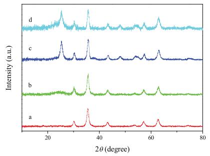
X-ray diffraction (XRD) pattern of the as-prepared Fe3O4 particles displays six well-resolved diffraction peaks centered at 30.4°, 35.6°, 43.3°, 53.7°, 57.3° and 62.7°/2θ (Fig. 1a), which are indexed to (220), (311), (400), (422), (511) and (440) reflections of the typical cubic Fe3O4 (JCPDS card No. 190629) [30]. After coating SiO2 on Fe3O4 surface, the pattern containing six diffraction peaks in Fe3O4@SiO2 is quite similar to that of the parent Fe3O4 microspheres, but a broad peak at around 22°/2u appears, which is corresponding to the amorphous SiO2 phase (Fig. 1b) [31]. Without calcination, the deposited TiO2 shell still shows the amorphous phase in Fe3O4@SiO2@TiO2 (Fig. S1 in Supporting information). Calcination at 400 ℃ promotes TiO2 crystallization into anatase phase with the characteristic diffraction peaks at 25° and 48°/2θ (Fig. 1c), that can be assigned to the (101) and (200) crystal planes of anatase TiO2 (JCPDS card No. 21-1272) [32], indicating that crystallized TiO2 was successfully coated on Fe3O4@SiO2. Nevertheless, after decorating Pt nanoparticles by wet impregnation and H2 reduction, the diffraction pattern of Fe3O4@SiO2@Pt/mTiO2-x remains unchanged, and no diffraction peaks about Pt nanoparticles were detected (Fig. 1d), which may be due to their low loading content and high dispersity in TiO2-x layer.

|
Download:
|
| Fig. 1. XRD patterns of (a) Fe3O4, (b) Fe3O4@SiO2, (c) Fe3O4@SiO2@mTiO2 and (d) Fe3O4@SiO2@Pt/mTiO2-x composites. | |
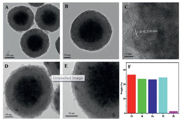
Using the solvothermal synthesis method, we have synthesized the hydrophilic magnetic Fe3O4 particles, which present the uniform spherical morphology with a mean diameter of 200 nm (Fig. S2A in Supporting information). These particles actually consist of a great number of magnetite nanocrystals in size of about 10 nm, so they have rough surface and pomegranate-like microstructures with superparamagnetic property. Notably, the surface of Fe3O4 particles is anchored with a great number of citrate groups, thus they can be well dispersed in polar solvents of water and ethanol, which is conductive to the subsequent deposition of silica layer. After controllable hydrolysis and condensation of TEOS through a sol-gel process, a nonporous SiO2 layer was uniformly coated on Fe3O4 particles to form the core-shell Fe3O4@SiO2 microspheres, presenting spherical morphology but much smoother surface and larger particle size of about 300 nm (Fig. S2B in Supporting information). TEM images indicate that the thickness of the silica shell is around 50 nm (Figs. 2A and B), in good consistence with the SEM image in Fig. S2B. As a transitional and protective layer, the SiO2 shell provides an appropriate interface for following deposition of TiO2 layer, and it can also enhance the stability and reusability of Fe3O4 particles and promote the photocatalytic activity of TiO2 by decreasing the adverse influence of Fe3O4 cores. Under the similar sol-gel coating procedure and followed calcination treatment, the second layer of anatase TiO2 was controllably deposited on SiO2 surface, leading to the well-defined Fe3O4@SiO2@mTiO2 microspheres with much larger particle diameter of ~340 nm but rough surface (Fig. S2C in Supporting information), mainly due to faster hydrolysis and condensation rate of TBOT than TEOS and formation of crystallized TiO2 nanoparticles by calcination. TEM images in Figs. 2A and B clearly reveal the typical three-layer sandwich structure of Fe3O4@SiO2@mTiO2, which consists of a dark Fe3O4 core, a lightcolored silica interlayer and a TiO2 shell with rough surface and thickness of around 20 nm. Notably, the TiO2 layer is composed of numerous highly crystallized nanocrystals with the lattice spacing of 0.316 nm (Fig. 2C), assigned to the (101) plane of anatase TiO2 [33], and the disordered mesopores are ascribed to the voids aggregated by these nanoparticles. After decorating Pt nanoparticles through wet impregnation and H2 reduction, the sample of Fe3O4@SiO2@Pt/mTiO2-x still shows the spherical morphology, uniform particle size and good dispersibility (Fig. S2D in Supporting information). From TEM images of Figs. 2D and E, it can be seen that Pt nanoparticles of ~3.5 nm in size are highly dispersed inside the mesoporous TiO2-x shells. The energy-dispersive X-ray spectroscopy (EDX) spectrum confirms the existence of Fe, Si, Ti and Pt elements in these core-shell microspheres (Fig. 2F), in which Pt content is calculated to be about 1.45%.

|
Download:
|
| Fig. 2. TEM (A, B) and HRTEM images (C) of Fe3O4@SiO2@mTiO2; TEM images (D and E) and EDS spectrum (F) of Fe3O4@SiO2@Pt/mTiO2-x. | |
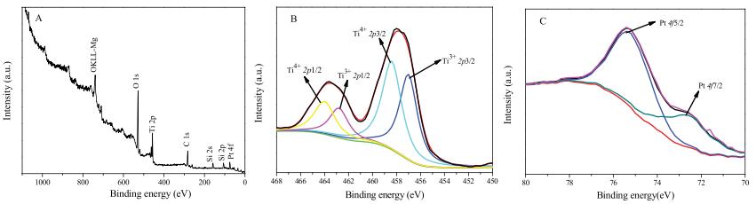
X-ray photoelectron spectroscopy (XPS) was used to examine the compositions and valence states of surface elements in Fe3O4@SiO2@Pt/mTiO2-x, in which the elements of O, Si, Ti and Pt could be detected but no peaks about Fe element appear (Fig. 3A), proving that the magnetic Fe3O4 core is well encapsulated inside the core-shell microspheres. Two main peaks centered at 458.2 and 464.1 eV (Fig. 3B) can be assigned to the Ti4+ 2p3/2 and Ti4+ 2p1/2, respectively. In addition, two additional peaks at 456.7 and 462.8 eV can be attributed to Ti3+ 2p3/2 and Ti3+ 2p1/2 respectively [34-36], revealing the existence of Ti3+ in the shell with Ti3+/Ti4+ ratio as high as 0.72. The result demonstrates that most of the tetravalent titanium was reduced to Ti3+ through H2 treatment at high temperature, which can greatly suppress the recombination of photoinduced electron-hole pairs and promote charge separation [37], thus enhancing the photocatalytic activity of the core-shell microspheres. Two fitted peaks at 75.5 and 72.2 eV demonstrate the production of Pt0 4f5/2 and Pt0 4f7/2, respectively (Fig. 3C), which indicates that Pt nanoparticles reduced by H2 treatment are uniformly decorated in TiO2-x shells [38].

|
Download:
|
| Fig. 3. XPS characterization of Fe3O4@SiO2@Pt/mTiO2-x. (A) XPS survey spectrum, (B) Ti 2p spectrum and (C) Pt 4f spectrum. | |
Fig. S3A (Supporting information) shows the nitrogen adsorption-desorption isotherm curves of Fe3O4@SiO2@mTiO2 and Fe3O4@SiO2@Pt/mTiO2-x, both of which display Type Ⅳ isotherm with an obvious hysteresis loop, indicating the formation of welldeveloped mesopores in the core-shell structured samples [39]. The Brunauer-Emmett-Teller (BET) surface area and total pore volume of Fe3O4@SiO2@Pt/mTiO2-x are 72.4 m2/g and 0.060 cm3/g, respectively, quite close to those of Fe3O4@SiO2@TiO2 (69.2 m2/g and 0.057 cm3/g). The pore size distributions derived from the adsorption branches of the isotherms by using Barrett-JoynerHalenda (BJH) model display a mean pore size of around 4.5 nm for both samples (Fig. S3B in Supporting information), indicating that the mesopores in TiO2 shell are completely open even after loading Pt nanoparticles, which can effectively contribute to fast adsorption and mass diffusion during the photocatalytic reaction.
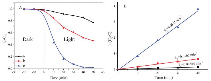
Due to the intrinsic magnetic property and the unique coreshell structure with high surface area and Pt-decorated oxygendeficient mesoporous TiO2-x, it is believed that the sample of Fe3O4@SiO2@Pt/mTiO2-x may have a potential use as the photocatalyst for RhB degradation under visible light irradiation, in comparison with the catalytic performance of Fe3O4@SiO2 and Fe3O4@SiO2@mTiO2 under the same evaluation conditions (Fig. 4). The Fe3O4@SiO2 core-shell hybrids show a negligible adsorption of RhB without visible light irradiation (in dark), mainly due to the low adsorption capacity of nonporous SiO2 shell. Whereas, both Fe3O4@SiO2@mTiO2 and Fe3O4@SiO2@Pt/mTiO2-x give an obvious increase in RhB adsorption, because of large surface area of the deposited mesoporous TiO2 shells and their strong affinity with RhB. Under the visible light irradiation, the Fe3O4@SiO2@Pt/ mTiO2-x core-shell hybrids exhibit the best catalytic performance with RhB degradation efficiency up to 98% within 50 min (Fig. 4A, curve c and Fig. S4B in Supporting information). For comparison, Fe3O4@SiO2 and Fe3O4@SiO2@mTiO2 can only convert 24% and 55% of RhB under the same conditions, respectively (Fig. 4A, curves a and b and Fig. S4A in Supporting information), indicating that the photocatalytic activity can be significantly enhanced by coating highly crystallized mesoporous anatase TiO2-x shell and decorating Pt nanoparticles as well. It is well known that most of the photocatalytic reactions can be fitted with the typical LangmuirHinshelwood model [4], and here the equation of ln(C0/C) = kt is adopted to calculate the apparent rate constant (k), where C0 and C are the initial concentration and the concentration of RhB at different exposed time, respectively. The k value of RhB degradation for Fe3O4@SiO2@Pt/mTiO2-x is calculated to be 0.0942 min-1 (Fig. 4B), which is 24.5 and 5.71 times higher than that of Fe3O4@SiO2 (0.00384 min-1) and Fe3O4@SiO2@mTiO2 (0.0165 min-1), respectively, further indicating the superior photocatalytic performance of the Fe3O4@SiO2@Pt/mTiO2-x coreshell hybrids towards RhB degradation.

|
Download:
|
| Fig. 4. (A) Photocatalytic degradation performance of RhB on various core-shell structured catalysts; (B) Pseudo-first-order linear relationship between reaction time and ln (C0/C), where C0 and C represent the initial concentration and the concentration of RhB at different exposed time, respectively: Fe3O4@SiO2 (a), Fe3O4@SiO2@mTiO2 (b) and Fe3O4@SiO2@Pt/mTiO2-x (c). | |
The stability and reusability of catalysts for continuous degradation of organics are quite important for practical application in industry. Five-cycle experiments were conducted to demonstrate the recyclability of Fe3O4@SiO2@Pt/mTiO2-x for RhB photodegradation in Fig. S5 (Supporting information). In each run, the photocatalyst can stably receive higher than 98% of degradation efficiency within 50 min, which was then completely and quickly separated from the aqueous solution held in an applied magnetic field for the consecutive catalytic evaluations. After five cycles of photocatalytic determinations, there was no significant loss of catalytic activity and magnetic strength even under visible light irradiation longer than the total exposed time of 250 min, indicating that the Fe3O4@SiO2@Pt/mTiO2-x core-shell microspheres are very stable and highly reactive with a long life time during the photocatalytic test.
Fig. S6 (Supporting information) describes the mechanism of photocatalytic degradation of RhB over oxygen-deficient Fe3O4@SiO2@Pt/mTiO2-x microspheres under visible light irradiation. At first, the irradiation of visible light can inspire the generation of conduction band electrons (e-) and valence band holes (H+) of TiO2-x in mesoporous shell. Due to the effective combination of highly-dispersed Pt nanoparticles and partiallyreduced anatase TiO2-x, the photogenerated electrons in the conduction bands can easily transfer to the Pt surface, which greatly prohibits the electron-hole recombination rate. Then O2 molecules capture electrons from the surface of Pt nanoparticles, to form the highly active O2- species, which can quickly oxidize organics into CO2 and water. From the mechanism investigation, the excellent photocatalytic performance of Fe3O4@SiO2@Pt/ mTiO2-x photocatalyst can be attributed to the following characteristics: (1) The mesoporous structure of thin TiO2-x shell, which is beneficial for the adsorption and diffusion of large organic molecules; (2) High crystallization of the TiO2-x layer, which contains rich defects and active sites exposed to reactants; (3) The loaded Pt nanoparticles could act as the electron traps to facilitate the separation of photogenerated electron-hole pairs and promote the electron transfer process between the interface of TiO2-x and Pt; (4) The silica interlayer and magnetic Fe3O4 core can enhance the stability and recyclability of the photocatalyst, respectively.
In summary, we report a conventional stepwise sol-gel coating approach to synthesize the magnetic core-shell Fe3O4@SiO2@mTiO2 microspheres, which exhibit the novel three-layer sandwich structure containing Fe3O4 cores of ~200 nm in diameter, nonporous SiO2 insulating layers of about 50 nm in thickness and mesoporous anatase TiO2 shells of 4.5 nm in pore size and 20 nm in thickness. Using the facile wet impregnation and H2 reduction routes, the magnetic core-shell photocatalyst of oxygendeficient Fe3O4@SiO2@Pt/mTiO2-x nanocomposites were obtained by uniform decoration of Pt nanoparticles in size of ~3.5 nm within the mesopores of TiO2-x shells, which were formed by TiO2 reduction combined with Pt deposition through H2 treatment. The photocatalytic activity of the core-shell Fe3O4@SiO2@Pt/mTiO2-x microspheres was evaluated by RhB degradation under visible light irradiation, and the photocatalytic efficiency can exceed 98% within 50 min, showing the highest k in comparison with other core-shell nanocomposites of Fe3O4@SiO2 and Fe3O4@SiO2@mTiO2. The recycling experiments indicate the promising stability and reusability in RhB photodegradation. The catalytic mechanism based on this core-shell Fe3O4@SiO2@Pt/mTiO2-x photocatalyst was supposed to further interpret the superior photocatalytic performance, which mainly originates from the magnetic coreshell structures and the synergistic effects of uniformly dispersed Pt nanoparticles, highly crystallized mesoporous anatase TiO2-x and nonporous SiO2 transitional layer.
Declaration of competing interestThe authors declare that they have no known competing financial interests or personal relationships that could have appeared to influence the work reported in this paper.
AcknowledgmentsThis work was supported by the National Natural Science Foundation of China (Nos. 51372041, 51422202, 21673048, 21875044, 51822202 and 51772050), Key Basic Research Program of Science and Technology Commission of Shanghai Municipality (No. 17JC1400100), Youth Top-notch Talent Support Program of China, Shanghai Rising-Star Program (No. 18QA1400100) and DHU Distinguished Young Professor Program.
Appendix A. Supplementary dataSupplementary material related to this article can be found, in the online version, at doi:https://doi.org/10.1016/j.cclet.2019.10.016.
| [1] |
J.L. Martinez, Environ. Pollut. 157 (2009) 2893-2902. DOI:10.1016/j.envpol.2009.05.051 |
| [2] |
N. Pugazhenthiran, P. Sathishkumar, P. Maruthamuthu, S. Anandan, J. Porous Mater. 20 (2013) 489-499. DOI:10.1007/s10934-012-9620-z |
| [3] |
M Eisenstein, Nature 521 (2015) S52. DOI:10.1038/521S52a |
| [4] |
L. Tang, Y. Liu, J. Wang, et al., Appl. Catal. B:Environ. 231 (2018) 1-10. DOI:10.1016/j.apcatb.2018.02.059 |
| [5] |
S. Fang, X. An, H. Liu, et al., Bioresour. Technol. 185 (2015) 28-34. DOI:10.1016/j.biortech.2015.02.078 |
| [6] |
L. Qin, D. Huang, P. Xu, et al., J. Colloid Interface Sci. 534 (2019) 357-369. DOI:10.1016/j.jcis.2018.09.051 |
| [7] |
B. Huang, J. He, S. Bian, et al., Chin. Chem. Lett. 29 (2018) 1698-1701. DOI:10.1016/j.cclet.2018.01.004 |
| [8] |
Y. Lv, L. Yu, C. Li, L. Yang, Sci. Chin. Chem. 59 (2016) 142-149. DOI:10.1007/s11426-015-5438-2 |
| [9] |
X. Lu, G. Wang, T. Zhai, et al., Nano Lett. 12 (2012) 1690-1696. DOI:10.1021/nl300173j |
| [10] |
J. Du, J. Qi, D. Wang, Z. Tang, Energy Environ. Sci. 5 (2012) 6914-6918. DOI:10.1039/c2ee21264a |
| [11] |
J.B. Joo, Q. Zhang, I. Lee, et al., Adv. Funct. Mater. 22 (2012) 166-174. DOI:10.1002/adfm.201101927 |
| [12] |
M. Wang, J. Han, H. Xiong, R. Guo, Langmuir 31 (2015) 6220-6228. DOI:10.1021/acs.langmuir.5b01099 |
| [13] |
S.I. Naya, A. Inoue, H. Tada, J. Am. Chem. Soc. 132 (2010) 6292-6293. DOI:10.1021/ja101711j |
| [14] |
D. Yang, H. Liu, Z. Zheng, et al., J. Am. Chem. Soc. 131 (2009) 17885-17893. DOI:10.1021/ja906774k |
| [15] |
J. Lu, P. Zhang, A. Li, et al., Chem. Commun. 49 (2013) 5817-5819. DOI:10.1039/c3cc42029a |
| [16] |
T. Yui, A. Kan, C. Saitoh, et al., ACS Appl. Mater. Interfaces 3 (2011) 2594-2600. DOI:10.1021/am200425y |
| [17] |
H. Liang, B. Zhang, H. Ge, et al., ACS Catal. 7 (2017) 6567-6572. DOI:10.1021/acscatal.7b02032 |
| [18] |
H. Li, Z. Bian, J. Zhu, et al., J. Am. Chem. Soc. 129 (2007) 4538-4539. DOI:10.1021/ja069113u |
| [19] |
X. Li, J. Wang, M. Li, et al., Chin. Chem. Lett. 29 (2018) 527-530. DOI:10.1016/j.cclet.2017.09.007 |
| [20] |
R. Asahi, T. Morikawa, T. Ohwaki, et al., Science 293 (2001) 269-271. DOI:10.1126/science.1061051 |
| [21] |
D. Chen, D. Yang, Q. Wang, Z. Jiang, Ind. Eng. Chem Res. 45 (2006) 4110-4116. DOI:10.1021/ie0600902 |
| [22] |
J. Seo, H. Lee, H.J. Lee, et al., Appl. Catal. B:Environ. 225 (2018) 487-495. DOI:10.1016/j.apcatb.2017.12.009 |
| [23] |
F. Zhang, Y. Shi, Z. Zhao, et al., Appl. Catal. B:Environ. 150-151 (2014) 472-478. |
| [24] |
W. Wang, D. Zhu, Z. Shen, et al., Ind. Eng. Chem. Res. 55 (2016) 6373-6383. DOI:10.1021/acs.iecr.6b00618 |
| [25] |
H. Li, J. Li, Y. Zhu, et al., Anal. Chem. 90 (2018) 5496-5502. DOI:10.1021/acs.analchem.8b01178 |
| [26] |
D. Beydoun, R. Amal, G.K.C. Low, S. McEvoy, J. Phys. Chem. B 104 (2000) 4387-4396. DOI:10.1021/jp992088c |
| [27] |
Y. Zhang, Q. Yue, L. Yu, et al., Adv. Mater. 30 (2018) e1800345. DOI:10.1002/adma.201800345 |
| [28] |
Y. Deng, D. Qi, C. Deng, et al., J. Am. Chem. Soc. 130 (2008) 28-29. DOI:10.1021/ja0777584 |
| [29] |
V. Belessi, D. Lambropoulou, I. Konstantinou, et al., Appl. Catal. B:Environ. 87 (2009) 181-189. DOI:10.1016/j.apcatb.2008.09.012 |
| [30] |
X.W. Lou, L.A. Archer, Adv. Mater. 20 (2010) 1853-1858. |
| [31] |
Y. Zhu, E. Kockrick, T. Ikoma, et al., Chem. Mater. 21 (2009) 2547-2553. DOI:10.1021/cm900956j |
| [32] |
S.D. Perera, R.G. Mariano, K. Vu, et al., ACS Catal. 2 (2012) 949-956. DOI:10.1021/cs200621c |
| [33] |
T. Yang, J. Peng, Y. Zheng, et al., Appl. Catal. B:Environ. 221 (2018) 223-234. DOI:10.1016/j.apcatb.2017.09.025 |
| [34] |
J. Chen, W. Song, H. Hou, et al., Adv. Funct. Mater. 25 (2016) 6793-6801. |
| [35] |
G. Li, Z. Lian, X. Li, et al., J. Mater. Chem. 3 (2015) 3748-3756. DOI:10.1039/C4TA02873B |
| [36] |
S.T. Myung, M. Kikuchi, S.Y. Chong, et al., Energy Environ. Sci. 6 (2013) 2609-2614. DOI:10.1039/c3ee41960f |
| [37] |
S.H. Szczepankiewicz, J.A. Moss, M.R. Hoffmann, J. Phys. Chem. B 106 (2002) 2922-2927. DOI:10.1021/jp004244h |
| [38] |
J.S. Jang, S. Yu, S.J. Choi, et al., Small 12 (2016) 5989-5997. DOI:10.1002/smll.201602204 |
| [39] |
L. Pinho, M.J. Mosquera, J. Phys. Chem. C 115 (2011) 22851-22862. DOI:10.1021/jp2074623 |