 2020, Vol. 31


b Beijing Key Laboratory for Theory and Technology of Advanced Battery Materials, Department of Materials Science and Engineering, College of Engineering, Peking University, Beijing 100871, China
Oxygen reduction reaction (ORR) is a key reaction for various energy conversion and storage systems, such as fuel cell and metal-air battery [1-3]. Their commercial application is limited by sluggish kinetics of ORR at the cathode, thus efficient catalysts are highly required. Up to now, the only commercialized Pt-based catalysts suffer from poor stability, crustal rarity, and prohibitive price. Hence, great efforts are devoted to developing non-precious metal catalysts to replace Pt-based catalysts. As one of the most promising candidates, transition metal (such as Fe and Co) atomically dispersed on nitrogen-doped carbon (M–N/C) catalysts exhibit superb ORR electrocatalytic activity and excellent stability [4-7]. Recently, single-atom catalysts are attracting increasing interests because of the presence of abundant highly active atomically dispersed metal sites (ADMS) [8-11]. Unique electronic structure and 100% atomic utilization of ADMSs lead to desirable electrochemical activity for ORR. However, the rational design of ideal ADMS-based carbon supports with expected structures and compositional features still remains a great challenge to date.
Electrospinning technique becomes a new research focus for energy conversion and storage field, which is a facile and scalable method to prepare carbon nanofibers [12-14]. The interpenetrating one-dimensional structure provides excellent passway for electron transportation and large surface for high expose of ADMSs. By structuring metal-organic frameworks (MOFs) into nanofibers, porous carbon nanofibers with well-dispersed ADMSs can be procured after carbonization [15, 16]. Fastened mass transport can be achieved by hierarchical pore structure bring by MOF nanocrystals. Herein, we fabricated atomically Fe-N4 sites dispersed hierarchical porous carbon nanofibers (Fe0.25@CNF) carbonized from electrospun of polyacrylonitrile (PAN) nanofibers embedded with aerogel of Fe0.25Al0.75-BTC. The resulting carbon nanofibers own hierarchical pore structure, high N-doping level and well dispersed ADMSs active sites. The special characteristics make Fe0.25@CNF exhibits high ORR activity with an onset potential of 0.994 V and a half-wave potential of 0.876 V, comparable to the benchmark commercial Pt/C catalyst.
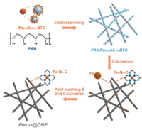
The synthesis procedure for Fex@CNF is schematically depicted in Scheme 1. First, FexAl1-x-BTC metal-organic aerogels (MOAs) were synthesized through the previously reported method [17, 18]. Due to poor crystallinity, the 3D microlites networks FexAl1-x-BTC-MOAs possess weak diffraction peaks in powder X-ray diffraction (PXRD) patterns (Figs. S1 and S2a in Supporting information). Then, FexAl1-x-BTC-MOAs were embedded into PAN nanofibers by a facile single-nozzle electrospinning method, which was support and carbon source to carbon nanofibers. For the purpose of conforming MOAs' dispersion, PXRD, scanning electron microscopic (SEM), and transmission electron microscopic (TEM) characterizations were performed. The diffraction peaks of FexAl1-x-BTC-MOAs could be identified in the PXRD patterns of FexAl1-x-BTC-PAN (Fig. S2b in Supporting information). Both SEM and TEM images illustrated the homogeneously loading of aerogels and the continuity and uniformity of MOA-PAN nanofibers precursor with average diameters of ca. 200 nm (Figs. S3 and S4 in Supporting information). During pyrolysis at 900 ℃ under an argon atmosphere, Fe3+ ions would be reduced by adjacent carbon species, and some of them were trapped by N and form Fe-Nx clusters through the Lewis acid-base interactions [13, 19]. The MOA-PAN precursors transformed into N-doped carbon nanofibers with atomically dispersed Fe-Nx sites. Extra Fe and Al species were removed by acid leaching, forming abundant pore structures. The second calcination is necessary to improve the graphitization of carbon and remove unstable functional groups bring by acid etching. For comparison, FexAl1-x-BTC MOAs were treated by the same processes obtaining porous carbon materials named Fex/C.

|
Download:
|
| Scheme 1. Schematic illustration of the synthetic process for Fe0.25@CNF. | |
The board peaks at≈26 in PXRD patterns of Fex@CNF corresponded to the (002) plane of graphitic carbon, and the diffraction peaks shifted to 26.5, indicating more formation of graphitized carbon with increasing of iron content (Fig. 1a). Additionally, diffraction peaks of Fe1@CNF are indexed to Fe3C (JCPDS No. 89-2867) phase. The graphitization degree information of Fex@CNF could be further provided by Raman spectra (Fig. 1b) [20]. The intensity ratios of the tangential stretch G band (≈1350 cm 1) to the disorder-induced D band (≈1580 cm 1) for Fex@CNF increase from 0.94 to 0.98 with the increase of Fe3+ molar ratio from 0 to 1. The surface areas and pore characteristics of all samples were characterized by 77 K isothermal N2 sorption measurements (Fig. 1c, Figs. S5 and S6 in Supporting information). N2 sorption curves of Fe0.25@CNF showed type-IV isotherms with obvious hysteresis loops indicating the existence of mesopores. The specific Brunauere Emmette Teller (BET) surface area and pore size distribution (PSD) of Fex@CNF were summarized in Table S1 (Supporting information). The BET surface area of Fe0.25@CNF was calculated to be 386 m2/g. PSD revealed that micro- and mesopores constructed hierarchical structures in nanofibers (Fig. 1c insert). The full X-ray photoelectron spectroscopic (XPS) spectrum revealed surface nitrogen content in Fe0.25@CNF was 4.99 at% (Fig. S7 in Supporting information). The total nitrogen of Fe0.25@CNF was 8.51 wt% revealed by element analysis (EA) (Table S2 in Supporting information). Inductively coupled plasma-atomic emission spectroscopy (ICP-AES) analysis indicated that the Fe content of Fe0.25@CNF was 0.18 wt%, while no significant Fe 2p peak could be detected due to low content (Fig. S7 in Supporting information). As shown in Fig. 1d, high-resolution spectra of N 1s could be deconvoluted into five peaks with binding energies of 398.0, 399.3, 400.4, 401.0 and 403.5 eV corresponded to pyridinic N (Py-N), iron-coordinated (Fe-N), pyrrolic (Pyr-N), graphitic-like (G-like), and oxidized type (Py-N-O) nitrogen, respectively (Fig. 1d) [5].

|
Download:
|
| Fig. 1. (a) PXRD patterns of Fex@CNF catalysts. (b) Raman spectra of Fex@CNF catalysts. (c) N2 sorption isotherms at 77 K for Fe0.25@CNF, inset shows the corresponding pore size distributions. (d) High-resolution N 1s XPS spectrum of Fe0.25@CNF. | |
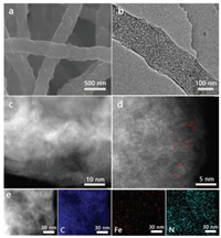
SEM and TEM images revealed that Fe0.25@CNF consists of uniform and continuous nanofibers with average diameters of ca. 200 nm (Figs. 2a and b). Lots of uniform pore structures distributed on the surface and inside of the fibers, which attribute to iron particles removed by acid etching. Other four Fex/C samples possessed metal bulks and nonporous carbon, which impeded the accessibility of active sites (Fig. S10 in Supporting information). As shown in TEM images of Fe0.25@CNF, there are no crystalline iron nanoparticles or Fe clusters are observed, this provides the significant evidence that the iron has deposited in single-atom sites rather than aggregating into large assemblies. To confirm the existence of ADMSs in Fe0.25@CNF, atomic-resolution high-angle annular dark-field scanning transmission electron microscopy (HAADF-STEM) was performed (Figs. 2c and d). Numerous isolated bright dots indicated the existence of Fe-N4 ADMSs, and some of them marked with red cycles in Fig. 2d. Energy-dispersive X-ray spectroscopy (EDS) mapping analysis indicated the uniform elemental distribution of C, N and Fe in Fe0.25@CNF (Fig. 2e).

|
Download:
|
| Fig. 2. (a) SEM, (b) TEM, (c, d) Aberration-corrected HAADF-STEM images and (e) corresponding EDS elemental mappings of Fe0.25@CNF. | |
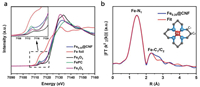
X-ray absorption near-edge structure (XANES) and extended X-ray absorption fine structure (EXAFS) analysis were performed to investigate the oxidation states and local coordination environment of Fe0.25@CNF (Fig. 3). The Fe K-edge XANES showed that Fe oxidation state was close to FeII as in FePc. The magnitude of Fourier transformed k2-weighted Fe K-edge EXAFS spectrum exhibited the main peak at 1.44 Å. Using FePc as basic structure model, the fitting result proves that the main peak was assigned to Fe–N1 coordination in the first shell. The second peak around 2.3 Å was assigned to Fe-C1/C2 coordination in the second shell. The absence of metallic Fe–Fe coordination certified that Fe sites were atomically dispersed in Fe0.25@CNF.

|
Download:
|
| Fig. 3. (a) Fe K-edge XANES spectra of Fe0.25@CNF, Fe foil, Fe2O3, FePC and Fe3O4. Inset shows the Fe K-edge pre-edge XANES. (b) Magnitude of Fourier transformed Fe K-edge EXAFS spectrum and the corresponding fitting curve of Fe0.25@CNF. | |
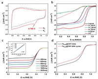
In consideration of the advantages of single atomic Fe-N4 active sites well-distributed in abundant pores, the Fe0.25@CNF was considered to be an efficient catalyst for the oxygen reduction reaction with high stability. The performance of Fex@CNF was measured by cyclic voltammetry and linear sweep voltammetry in a 0.1 mol/L KOH solution using a three-electrode configuration. Fig. 4a reveals that a well-defined cathodic peak with a positive peak potential for Fe0.25@CNF was measured in O2-saturated electrolyte, which implied the electrocatalytic activity towards ORR. The ORR performance of Fex@CNF was further investigated by linear sweep voltammetry (LSV) using rotating-disk electrode (RDE). As shown in Fig. 4b and Table S3 (Supporting information), the best ORR catalytic performance was achieved by Fe0.25@CNF with a positive onset potential of 0.994 V and half-wave potential of 0.876 V, which close to that of the commercial Pt/C catalyst.

|
Download:
|
| Fig. 4. (a) CVs of Fe0.25@CNF in O2-saturated 0.1 mol/L aqueous KOH (scan rate: 50 mV/s). (b) ORR polarization curves of Fex@CNF and Pt/C catalysts in O2-saturated 0.1 mol/L KOH (scan rate: 10 mV/s, rotating speed: 1600 rpm). (c) ORR polarization curves of Fe0.25@CNF at various rotating speeds in O2-saturated 0.1 mol/L KOH (scan rate: 10 mV/s), inset shows corresponding Koutecky-Levich plots at various potentials. (d) ORR activity of Fe0.25@CNF before and after durability tests. | |
For further insight into the reaction mechanism, the kinetic parameters including electron transfer number (n) and kinetic-limiting current density (jK) were collected based on the polarization curves at various rotating speeds and corresponding Koutecky-Levich (K–L) plots (Fig. 4c). The electron transfer number for the Fe0.25@CNF sample provided direct evidence of the catalyst performance. The K–L plots displayed excellent linearity and near coincidence, indicating similar electron transfer number of per oxygen molecule in ORR at different potentials. The electron transfer number was calculated to be 3.90 for Fe0.25@CNF over the potential ranging from 0.25 V to 0.65 V, suggesting a preferred efficient four-electron pathway.
The long-term stability of Fe0.25@CNF was tested by accelerated durability tests by cycling the electrode potential between 0.6 V and 1.0 V for 8000 cycles. Fe0.25@CNF shown only a slight activity loss by ca. 20 mV negative shift in half-wave potential (Fig. 4d). Chronoamperometric measurements were employed to evaluate the long-term stability of Fe0.25@CNF during ORR process, showing a low attenuation with high retention of 62% over 30, 000 s (Fig. S12 in Supporting information). The outstanding stability of Fe0.25@CNF might be attributed to the strong interaction between Fe-N4 ADMSs and nitrogen-doped carbon substrates, which is consistent with reported works [21-23]. Furthermore, methanol crossover test showed that after addition of methanol into the electrolyte solution, no noticeable disturbance of the current density was observed for Fe0.25@CNF, whereas the Pt/C catalyst exhibited a dramatic change in the current density due to the methanol oxidation (Fig. S13 in Supporting information). These results indicated that Fe0.25@CNF possesses better electrocatalytic performance and durability than the commercial Pt/C catalyst for ORR in alkaline solutions.
The superb electrocatalytic performance of Fe0.25@CNF could be attributed to the following key aspects: (1) The 1D structure of Fe0.25@CNF provides a large exposed surface area and high electrical conductivity, which greatly enhances the electron-transfer capability and promoting the electrocatalytic performance for ORR. (2) Hierarchical pore structure could enhance mass transportation, where macro- and mesopores work as a reservoir for an electrolyte, which shortens the diffusion distance. (3) The special structure of Fe0.25@CNF creates extensive efficient Fe-N4 sites that could actually participate in ORR reaction with ultrahigh current density and superb stability.
In summary, we prepared a hierarchical structure of Fe-N4 sites well-dispersed porous carbon nanofibers via the thermal treatment of electrospun Fe0.25Al0.75-BTC@PAN composite precursor. The outstanding electrocatalytic performance of Fe0.25@CNF for ORR could be attributed to the special structure of 1D carbon nanofibrous structure with high surface area and pore volume, the proper degree of the graphitization, and high content of the active species. The present results open up new avenues for developing novel open carbon nanostructures with controllable morphology and functionality for the next generation of nonprecious electrocatalysts.
Declaration of competing interestThe authors declare no conflict of interest.
AcknowledgmentThis work was supported by the National Natural Science Foundation of China (Nos. 51772329, 51972340).
Appendix A. Supplementary dataSupplementary material related to this article can be found, in the online version, at doi:https://doi.org/10.1016/j.cclet.2019.12.004.
| [1] |
A. Kulkarni, S. Siahrostami, A. Patel, et al., Chem. Rev. 118 (2018) 2302-2312. DOI:10.1021/acs.chemrev.7b00488 |
| [2] |
M. Shao, Q. Chang, J. Dodelet, et al., Chem. Rev. 116 (2016) 3594-3657. DOI:10.1021/acs.chemrev.5b00462 |
| [3] |
Z. Wang, D. Xu, J. Xu, X. Zhang, Chem. Soc. Rev. 43 (2014) 7746-7786. DOI:10.1039/C3CS60248F |
| [4] |
H. Ren, Y. Wang, Y. Yang, et al., ACS Catal. 7 (2017) 6485-6492. DOI:10.1021/acscatal.7b02340 |
| [5] |
H. Shen, E. Gracia, J. Ma, et al., Nano Energy 35 (2017) 9-16. DOI:10.1016/j.nanoen.2017.03.027 |
| [6] |
A. Zitolo, V. Goellner, V. Armel, et al., Nat. Mater. 14 (2015) 937-942. DOI:10.1038/nmat4367 |
| [7] |
D. Li, H. Xu, L. Jiao, H. Jiang, Energ. Chem. 1 (2019) 100005. |
| [8] |
Z. Liang, C. Qu, D. Xia, et al., Angew. Chem. Int. Ed. 57 (2018) 9604-9633. DOI:10.1002/anie.201800269 |
| [9] |
R. Zhao, Z. Liang, S. Gao, et al., Angew. Chem. Int. Ed. 58 (2019) 1975-1979. DOI:10.1002/anie.201811126 |
| [10] |
J. Wang, Z. Huang, W. Liu, et al., J. Am. Chem. Soc. 139 (2017) 17281-17284. DOI:10.1021/jacs.7b10385 |
| [11] |
X. Xiao, Q. Li, X. Yuan, et al., Small Methods 2 (2018) 1800240. DOI:10.1002/smtd.201800240 |
| [12] |
C. Zhang, B. Lu, F. Cao, et al., Nano Energy 55 (2019) 226-233. DOI:10.1016/j.nanoen.2018.10.029 |
| [13] |
H. Yang, Y. Wu, G. Li, et al., J. Am. Chem. Soc. 141 (2019) 12717-12723. DOI:10.1021/jacs.9b04907 |
| [14] |
J. Zheng, Y. Yang, X. Fan, et al., Energy Environ. Sci. 12 (2019) 615-623. DOI:10.1039/C8EE02836B |
| [15] |
Z. Liang, R. Zhao, T. Qiu, et al., Energ. Chem. 1 (2019) 2589-7780. |
| [16] |
X. Wang, W. Chen, L. Zhang, et al., J. Am. Chem. Soc. 139 (2017) 9419-9422. DOI:10.1021/jacs.7b01686 |
| [17] |
W. Xia, B. Qiu, D. Xia, et al., Sci. Rep. 3 (2013) 1935. DOI:10.1038/srep01935 |
| [18] |
A. Mahmood, S. Li, Z. Ali, et al., Adv. Mater. 31 (2019) e1805430. DOI:10.1002/adma.201805430 |
| [19] |
P. Geng, S. Cao, X. Guo, et al., J. Mater. Chem. A:Mater. Energy Sustain. 7 (2019) 19466-19470. |
| [20] |
H. Huang, S. Yang, R. Vajtai, et al., Adv. Mater. 26 (2014) 5160-5165. DOI:10.1002/adma.201401877 |
| [21] |
Y. Chen, S. Ji, Y. Wang, et al., Angew. Chem. Int. Ed. 56 (2017) 6937-6941. DOI:10.1002/anie.201702473 |
| [22] |
H. Zhang, S. Hwang, M. Wang, et al., J. Am. Chem. Soc. 139 (2017) 14143-14149. DOI:10.1021/jacs.7b06514 |
| [23] |
L. Zhao, Y. Zhang, L. Huang, et al., Nat. Commun. 10 (2019) 1278. DOI:10.1038/s41467-019-09290-y |