 2020, Vol. 31


Crystalline porous materials with regular porosity, such as zeolites, metal-organic frameworks (MOFs), and covalent organic frameworks (COFs) have uniform pore size distribution, framework versatility and chemical diversity, which can be used as sorbents with high adsorption capacities, catalysts with high catalytic performance [1-4]. Various synthetic methods have been developed for porous materials, and hydrothermal or solvothermal synthesis is the most common way. Conventional synthesis of porous materials including MOFs, COFs, zeolites has been dominated by one-pot solution processing conditions carried out by bulk mixing under conventional electric heating via hydrothermal/solvothermal/ionothermal reactions where high temperatures and pressures are the standard [5]. These methods suffer from long operation times, low efficiencies and batch-dependent product properties or difficulty in controlling the stages of nucleation and particle growth. A series of new methods have been developed based on the conventional synthesis method, such as microwave-assisted synthesis [6], electrochemical synthesis [7], mechano-chemical synthesis [8], spray drying and sonochemical synthesis [6, 9, 10] methods to obtain new compounds with different particle sizes and size distributions as well as morphol-ogies [5]. Through an integrated use of these methods, crystalline porous materials containing diversity structure and special aperture can be obtained, which show excellent potential in energy efficiency. Besides, flow chemistry and continuous processing methods are receiving attention for the synthesis of porous materials [11-13].
Flow chemistry and continuous flow systems have received increasing attention in recent years. The assembly and use of continuous flow systems has been the subject of several reviews and articles [14-16]. A number of commercial units are also available. For lab-scale purposes, syringe, HPLC, or peristaltic pumps can be used to drive fluid through reactor coils or microfluidic chips, with the residence time of the fluid dictated by the total flow rate and reactor volume [16]. In some cases, these systems employ an inert, immiscible phase, typically silicone oil, to segment the flow, creating "slugs" of reactant solution, preventing particle aggregation and channel blockages, and further promoting internal mixing. The key advantages of microfluidic or flow chemistry systems include efficient mass and heat transfer, precise control of residence times, improved opportunities for automation and feedback control of synthesis, scaling-up reactions and improved safety parameters. The high degree of temperature control is achieved on small scales due to high surface area-to-volume ratios which essentially leads to beneficial isothermal reaction conditions. Mixing is often dictated by diffusion in flow systems due the laminar flow regimes within such microchannels. Diffusion timescales can be long which may slow reaction processes, however, if the diffusion path length is short, as it often is with the case of microchannels, then diffusion dominated mixing can in fact be fast. Turbulence can be induced in such systems in order to reduce mixing times by increasing flow rates, introducing an active mixer or by changing the channel size or structure. A range of reactor configurations can also be accessed and fabricated in a variety of materials [17]. The flow synthesis of a particular material can be easier to scale-up either by increasing the number of reactor units (socalled scaling-out) or by allowing the process to simply run continuously until enough material is produced. Production of materials in this way can be achieved without significant changes to the process and without compromising the product quality. Such flow processes are often much more efficient in terms of laboratory space usage and typically display much higher space-time yields (STYs) compared to batch reactions. Therefore, microfluidic devices and continuous flow systems have found numerous applications in the fine chemical/pharmaceuticals sector, polymer synthesis, biosensing, analytical chemistry and catalysis [18-27].
Production of porous materials via flow chemistry systems has key advantages in terms of safety, scalability and improving yields/selectivities compared to traditional batch scale synthetic methods. Microfluidic reactors reduce the characteristic reaction vessel length scale from centimeters to hundreds of micrometers, thus result in several important advantages including waste reduction, better temperature control and improvement in the kinetics of diffusion-limited reactions. In order for the production of a porous material to be industrially viable a number of key aspects have to be considered including the versatility, the possibility to avoid harsh processing conditions, a switch from batch to continuous processing and a high space-time yield parameter [11]. Microchannels have superior qualities for solvent extraction due to the small scale used (i.e., high surface-to-volume ratio, large specific interface area and short diffusion distance with short diffusion times). It is possible to develop solvent extraction systems with both high performance and speed in a microchannel without any mechanical shaking, mixing, or stirring required. Therefore, flow chemistry can be used in liquid-liquid extraction to separate and extract products effectively, allowing for the mechanism of the two-phase reaction to be explored [28]. In the reported examples, proper precursor solubility is required for continuous flow synthesis of porous materials. Additionally the concentration of precursor solution should be kept low to avoid channel blocking. Flow synthesis reactors can be divided into continuous single-phase laminar flow reactors and segmented or droplet-based reactors. Due to contact with the channel wall, the situation of gradual pollution of the channel may occur. The precursor solutions are dispersed as droplets and the flow comprises alternating segments of two immiscible liquids. Flow synthesis reactors lead to the high specific interfacial areas and the Taylor circulation vortices [29-32].
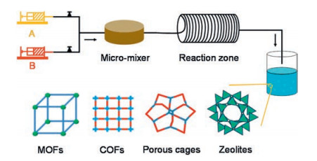
A number of excellent reviews have been devoted to various synthesis methods of porous materials [5-10], while the main purpose of this review is summarizing the continuous flow synthesis of various porous materials such as metal-organic frameworks (MOFs), covalent-organic frameworks (COFs), porous organic cages and zeolites (Fig. 1). The synthesis of crystalline porous materials is mainly focused on although other porous materials have been developed as well (e.g., continuous flow synthesis of porous silicas [33-35]). This review aims to give some inspiration on the future work of continuous flow synthesis of crystalline porous materials.

|
Download:
|
| Fig. 1. Schematic representation of the flow synthesis of MOFs, COFs, porous cages and zeolites. | |
2. Continuous flow synthesis of metal-organic frameworks (MOFs)
Several catalogues of MOFs have been investigated in detail and the synthetic methods have been developed, including MIL-series MOFs and analogs, UiO-66 and analogs, ZIF-8 and analogs, and others (Table 1).
|
|
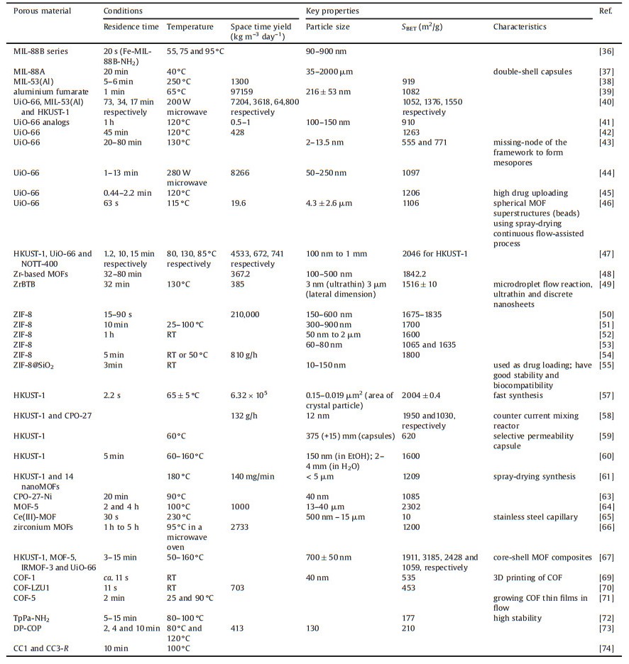
Table 1 Continuous flow synthesis of porous materials MOFs, COFs, and porous organic cages. |
2.1. MIL-series MOFs and analogs
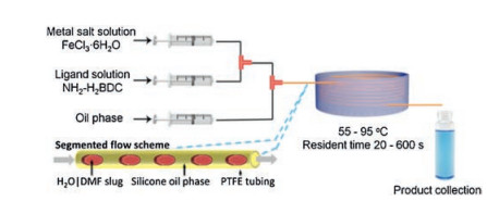
A number of MIL-series MOFs have been prepared by continuous flow approach [36-40]. MIL-88 series including Fe-MIL-88B-NH2 (NH2), Fe-MIL-88B (4H) and Fe-MIL-88B-Br (Br) with controlled particle sizes were prepared by microfluidic approach with segmented flow pattern by Coronas and co-workers [36]. As shown in Fig. 2, two reactant streams with a silicone oil stream are transferred to the mixing zone and then are injected into the reaction-hot zone. Residence times ranging from 60 s to 600 s are tuned according to the modification of the total flow rates, keeping the microreactor volume and the silicone oil/aqueous phase rate constant. With the use of microfluidic approach, the synthesis is significantly accelerated and Fe-MIL-88B-NH2, Fe-MIL-88B, and Fe-MIL-88B-Br are obtained after 20 s, 4 min and 6 min, respectively. Apart from ultrafast synthesis, the resulting crystals are clearly below 1 μm with narrow particle size distributions. Particle size distribution can be controlled by microfluidics. As demonstrated for Fe-MIL-88B-NH2, particle size increases continuously from average values of 180 nm to 900 nm as a function of residence time from 20 s to 600 s and a clear augmentation of the dispersion of the distributions was also observed.

|
Download:
|
| Fig. 2. Schematic representation of the microfluidic setup with reactants and silicone oil streams, and synthesis details. Copied with permission [36]. Copyright 2013, American Chemical Society. | |
MIL-88A framework hollow spheres were synthesised by Falcaro and co-workers via interfacial reaction in-droplet microfluidics, where a dispersion of metal precursor aqueous solution and a continuous oil phase of organic linker are introduced into a microfluidic channel through a T-junction [37]. The obtained MOF hollow spheres prepared at different residence times show a typical spherical morphology with tuneable size and uniform spherical shape, while higher crystallinity is obtained for a longer residence time (Fig. 3). With the use of microfluidics, it is able to achieve one-pot synthesis of the MOF as well as encapsulating biomolecules during the MOF formation. Additionally, microfluidic synthesis is continuous and scalable, and is able to control the size and shape of the MOF carrier, as well as achieve multishell architectures.

|
Download:
|
| Fig. 3. SEM images of single-shell MIL-88A microcapsules with various sizes: (a) 35 μm, (b) 200 μm, (c) 350 μm obtained via in-droplet microfluidic approach; (d) XRD patterns of MIL-88A microcapsules synthesized at different retention times; (e) SEM image of double-shell MIL-88A microcapsule with 310 μm of inner shell and 440 μm of outer shell (scale bars: 100 μm). Copied with permission [37]. Copyright 2015, American Chemical Society. | |
2.2. UiO-66 and analogs
Continuous synthesis of UiO-66 has been investigated in detail in a number of reports [40-47]. UiO-66 nanoparticles were prepared in a microfluidic system, in which the particle size can be tuned from hundreds to dozens of nanometers by controlling of the residence time [41]. Two streams of ZrCl4 in DMF solution and 1, 4-benzenedicarboxylic acid in DMF solution were supplied into a microflow reactor and mixed on-line by a T-mixer, and pumped to the hot reaction region. While the streams were smoothly passed through once the temperature was stable, products with different flow rate range from 0.1 mL/min to 0.5 mL/min were collected. The UiO-66 nanoparticles obtained at different rate in the microfluidic system show irregular shapes, and the particle size decreases from hundreds of nanometers to dozens of nanometers, confirming that the particle size can be well tuned by simply adjusting the residence time. Flow-synthesised UiO-66 material has been shown to possess higher thermal stability, lower symmetry, and defect rich regions incorporated within the structure, and the material has increased surface area due to defects [42].
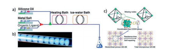
Hierarchical UiO-66 composed of mesopores with intercon-necting intrinsic micropores was prepared continuously through a microdroplet flow reaction strategy, and the engineering of pore structures was realized (Fig. 4) [43]. At a short reaction time, such as 20 min and 80 min, some metal-nodes are absent due to the incomplete coordination of metals with the carboxylate groups. With the increasing residence time, the decreasing content of defect rate of metal-nodes means that the missing-nodes are gradually repaired by self-healing of the coordination spheres in frameworks. On the contrary, no products are obtained in the solvothermal synthesis of UiO-66 at short reaction times. The portion of mesopores is linearly correlated to the missing-nodes, and the surface acidity is enhanced due to a large amount of coordinated-free carboxylate groups pending in pores. Owing to the enhanced porosity and the polarized coordinated-free carboxylate groups, these hierarchical porous MOFs exhibit 20% higher uptake capacity for CO2 and 16% higher uptake capacity for CH4 at high pressures.

|
Download:
|
| Fig. 4. (a) Schematic illustration of the microdroplet flow reaction system; (b) Photograph of segmented droplets in the coil; (c) Schematic illustration of the missing-node induced hierarchical porous structure of UiO-66. Copied with permission [43]. Copyright 2017, Royal Society of Chemistry. | |
Microwave-assisted continuous flow techniques have been developed for UiO-66 [40, 44]. The combination of microwave irradiation with continuous flow techniques offers considerable potential because microwave irradiation is an alternative method of heating. Ranocchiari and co-workers study the in situ high-resolution powder X-ray diffraction of the crystallization of UiO-66 in the continuous-flow microwave reactor [44], and found that the synthesis can be identified as two stages, a preliminary stage where the crystallite size increases, and a steady stage where the quality of the product is constant. The yield and crystallite size of the product primarily depend on the H2O/AcOH ratio, and increasing the absolute amounts of additives at fixed ratios leads to a higher yield of larger crystallites, while aging of the metal stock solution leads to a higher yield of smaller crystallites. The synthetic method of combing microfluidic and microwave assisted heating has been applied for MIL-53(Al) and HKUST-1 as well [40]. The calculated space-time yield for HKUST-1 is 66650 kg m-3 day-1, and can be up-scaled to process a total 500 mL of reaction mixture in 17 min using the same residence time and power, but working at 6 bar. When the reaction is conducted under continuous flow conditions with conventional heating replacing microwave irradiation, a decrease in space-time yield is observed (up to 42, 100 kg m-3 day-1).
Other Zr-MOFs were also synthesized through a microdroplet flow reaction [48]. Four types of Zr-based MOFs with different ligands and topologies (MF-MOF-801, MFMOF-804, MF-DUT-67, and MF-MOF-808, where MF represents "microdroplet flow") were produced as a pure phase of high quality crystalline with uniform morphologies. Zr-MOFs obtained from microdroplet flow reaction possess a higher degree of crystallinity and more uniform morphologies compared to conventional solvothermal synthesis, and show higher CO2/N2 selectivity over other Zr-MOFs. The space-time yield values for MF-MOF-801, MF-MOF-804, MF-DUT-67 and MF-MOF-808 are highly up to 367.2, 247.1, 114.3, and 136.4 kg m-3 day-1, respectively.
Functionalized analogs of UiO-66 have been investigated using microfluidic method [41, 45]. A continuous, scalable nanodroplet-based microfluidic route was reported to be efficient in the synthesis of functionalized UiO-66 analogs with desired functional groups (e.g., —COCH3, fluorescein isothiocyanate FITC) at a nanoscale (Fig. 5) [41]. Among them FITC functionalized UiO-66-NH2 is obtained in a very short time (1 h) compared to batch process (6-20 d). Activated nano-UiO-66-2-NH2 particles were used to load 5-fluorouracil for drug delivery [45]. The prepared nano-UiO-66-2-NH2 allows up to 27 wt% uploading of 5-fluorouracil and has a good sustained release ability with a calculated release rate of k constant 0.27 h-1 in phosphate buffer solution (PBS) solution at 37 ℃.

|
Download:
|
| Fig. 5. (a) Schematic illustration of FITC functionalization onto UiO-66-NH2, and SEM images of (b) UiO-66-NH2, (c) UiO-66-NHCOCH3 and (d) UiO-66-NH-FITC synthesized from the microfluidic system. Copied with permission [41]. Copyright 2016, Springer Nature. | |
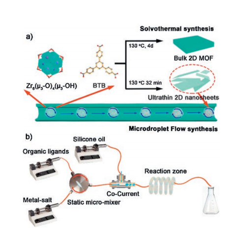
The dynamic reaction process is dominated by diffusion, forced convection and mass transfer processes in the microdroplet flow system, and it helps to limit the growth of 2D MOF along the vertical direction. This has been applied to produce ultrathin 2D ZrBTB nanosheets (MF-ZrBTB) with a high space-time yield of up to ~385 kg m-3 day-1 (Fig. 6) [49]. About 3 nm high ultrathin multilayered nanosheets are obtained for MF-ZrBTB. MF-ZrBTB has much higher BET surface area (1516±10 m2/g) than those of solvothermal ZrBTB, which arose from the larger external surface area of the ultrathin isolated or separated nanosheets. Due to the increased surface area, the ultrathin MF-ZrBTB nanosheets show a considerably better gas adsorption performance (~3 times for CO2 and 2.6 times for CH4) compared with the corresponding solvothermal ZrBTB.

|
Download:
|
| Fig. 6. Schematic illustrations of (a) the overall process to produce ZrBTB via microdroplet flow reaction and conventional solvothermal methods and (b) the experimental arrangement for microdroplet flow synthesis of ZrBTB. Copied with permission [49]. Copyright 2018, American Chemical Society. | |
2.3. ZIF-8 and analogs
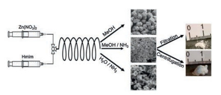
Continuous synthesis of ZIF-8 has been investigated by several groups [50-54]. Kaskel and co-workers reported that it is possible to intentionally tailor both the microscopic (crystal form and size) and macroscopic morphology of the product by modifying the reaction and process conditions (e.g., solvents, aging time) [50]. Experiments in pure MeOH exhibit generally low reaction yields (3%-10%), but no further purification and activation steps are required. The product is obtained at production rates of up to 640 g/day while synthesised in MeOH/NH3 (aq), which corre-sponds to a theoretical space-time yield of 210, 000 kg m-3 day-1. The modular process setup allows easy scale-up into the several-kilogram range. Additionally, by modifying the reaction and process conditions it is possible to intentionally tailor both the microscopic (crystal form and size) and macroscopic morphology of the product (Fig. 7). The high space-time yield achieved with this approach favours quantitative production, bringing these materi-als a step closer to a broader industrial exploitation.

|
Download:
|
| Fig. 7. Schematic illustration of the process used for the continuous synthesis of ZIF-8, and morphology of ZIF-8 crystals obtained via various solvents. Copied with permission [50]. Copyright 2016, Elsevier. | |
The synthesis of ZIF-8 via continuous processes was also studied by Schneider and co-workers [51]. ZIF-8 particles are synthesized either in a single-phase microfluidic system (water as sole solvent) or in a multi-phase flow where the water droplets are constrained in alkane to achieve narrow residence time distributions. The microfluidic technology enables the rapid synthesis (10 min) of ZIF-8 crystals with stable rhombic dodecahedron shape over a wide size range (from ca. 300-900 nm) simply by varying the experimental parameters such as flow rates and temperature, while maintaining the high specific surface of this material (ca. 1700 m2/g) and the sodalite crystalline structure. The crystal size increases when increasing the temperature (ca. 355±71 and 666 140 nm for reactions conducted at 25, 50 ℃, respectively) and then reaches a plateau (ca. 738 nm for reactions performed at 75 and 100 ℃).
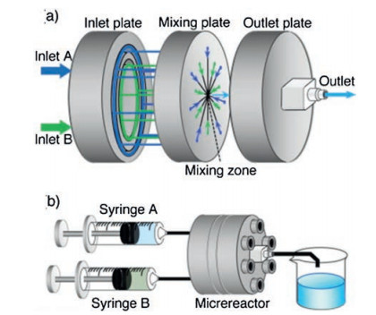
ZIF-8 particles were also synthesized using a central collision-type microreactor by Watanabe, Miyahara and co-workers [52]. A central collision-type microreactor is composed of inlet, mixing, and outlet plates (Fig. 8). Each of the two inlet solutions branches into seven channels at the inlet plate, and flow along the radially-arranged channels towards the centre of the mixing plate. The separated fluid streams collide with each other in the mixing zone, breaking into micron-sized segments of fluids owing to the shear forces acting among the colliding fluids. Thus, quick and homogeneous mixing is realized due to the shortened diffusion distance. The synthesis is additive-free and allows control of both particle size from 50 nm to 2 μm and particle shape from cube to chamfered cube to rhombic dodecahedron, simply by adjusting the concentration of feed solutions and reaction temperature. Particle size is determined by the mixing process in the microreactor while the particle shape is controlled by the temperature during the aging process after mixing. ZIF-8 particles synthesized using the microreactor have a narrower size distribution compared to those prepared using the batch-type reactor, and the particle size distributions for the different experimental runs are nearly identical, which showed improved reproducibility.

|
Download:
|
| Fig. 8. Schematic illustration of (a) central collision-type microreactor and (b) the experimental setup. Copied with permission [52]. Copyright 2017, Elsevier. | |
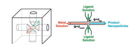
ZIF-8 nanoparticles with uniform diameters in the range of 60-80 nm involving a jet-mixing reactor were produced by Brunelli and co-workers [53]. A jet-mixing reactor involves using the kinetic energy of introduced impinging jet-streams to generate turbulence in the reactor volume, which can lead to increased mixing intensity, and provide more uniform reaction conditions. The jet-mixing reactor is built in-house using a cube of polyether ether ketone. It consists of a main line that has an inlet and outlet port, as shown in Fig. 9. The jet-mixing reactor is operated by pumping the metal solution through the main line and introducing the ligand solution through the jets, and the product suspension is collected downstream. While the synthesis of ZIF nanoparticles typically involves using excess ligand, the jet-mixing reactor is operated at ambient conditions using preferred solvents and stoichiometric quantities of ligand and metal (i.e., ligand:metal = 2:1) with yields as high as 89%. ZIF-8 synthesized using jet-mixing possess higher BET surface area (1534 m2/g) and larger t-plot pore volume (0.635 cm3/g) with narrower size distribution (74±15 nm).

|
Download:
|
| Fig. 9. Schematic illustration of jet-mixing reactor, reactor design with dj = jet inlet diameter and dr = main through-line diameter (dr/dj = 2), and flow pattern in the reactor. Copied with permission [53]. Copyright 2017, American Chemical Society. | |
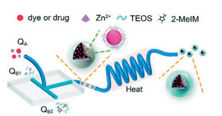
Stable and biocompatible drug-loaded ZIF-8@SiO2 nanocom-posites with optimal sizes (10-150 nm) were synthesized by microfluidic approach by Wang and co-workers [55]. A mixture of tetraethyl orthosilicate and 2-methylimidazole are simultaneously injected into two inlets QB1 and QB2 at a flow rate of 50 μL/min with a peristaltic pump at room temperature, then converge with a mixture of dye/drug and Zn2+ injected into inlet QA at a flow rate of 100 μL/min in the microfluidic system (Fig. 10). The product solution is continuously collected from the outlet. It is noticed that rose bengal (RB)-loaded ZIF-8@SiO2 nanocomposites have uniform shape, narrow size distribution (average size of 93.8±17.3 nm), and good stability. High loading dosage of 35.3 mg/mg and excellent biocompatibility make photodynamic therapy have anticancer value photodynamic therapy for cancers and demon-strate the enormous potential for this novel manufacturing strategy in the biomedical field.

|
Download:
|
| Fig. 10. Schematic illustration of the microfluidic system for the synthesis of drug@ZIF-8@SiO2. Inlet QA: A mixture of dye/drug and Zn2+; Inlets QB1 and QB2: A mixture of tetraethylorthosilicate and 2-methylimidazole. Copied with permission [55]. Copyright 2018, Royal Society of Chemistry. | |
2.4. Other MOFs
High-rate synthesis of HKUST-1 has been achieved using continuous flow chemistry method [40, 47, 56-62]. Polyzos, Hill and co-workers reported the products are rapidly synthesised without loss in quality with a space-time yield of HKUST-1 to be estimated to 4533 kg m-3 day-1 [56]. The crystal sizes of the products are smaller than the crystals obtained under standard solvothermal conditions, which is attributed to the rapid crystallization kinetics induced by the flow chemistry approach. Microwave heating has benefits such as significantly reducing production times (many hours to minutes), increasing product yield and purity, and improving product properties. Oscillatory baffled reactors were used to produce a homogeneous mixture of reactants and solid suspensions and to facilitate rapid heat transfer to the bulk mixture by Laybourn and co-workers [57]. Compared with other processing methods, microwave heating and continuous flow oscillatory baffled reactor show great potential in energy savings, enhanced process control and optimization, and improved product properties. HKUST-1 was fabricated at the 97.42 g/h scale, with a space-time yield of 6.32×10⁵ kg m-3 day-1 and surface area production rate of 1.12×10¹² m2 m-3 day-1.
Among a number of other MOFs [63-66], CPO-27-Ni was synthesized with a continuous synthesis route using tubular reactor techniques by Blom and co-workers [63]. When the reaction is performed at 90 ℃, a conversion of above 90% is reached in just 20 min. The resulting MOF has a specific surface area of around 1085 m2/g. SEM clearly shows that crystallite sizes around 40 nm are obtained when using the tubular reactor approach, while state-of-the-art batch synthesis in water typically gives micrometer-sized crystallites as product. The tubular reactor setup can be easily up-scaled by parallelization.
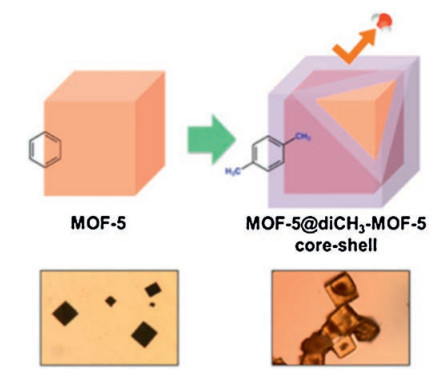
Core-shell MOF composites MOF-5@diCH3-MOF-5 was synthe-sized by exploiting a two-step integrated microfluidic synthesis scheme in a continuous-flow mode [67]. As shown in Fig. 11, this core-shell structure is prepared using the two-step serial microfluidic system. MOF-5@diCH3-MOF-5 comprises two types of organic ligands. The serial microfluidic process not only dramatically reduces the reaction time but also enables effective protection of the MOF-5 core from exposure to moisture during handling. In comparison with bare MOF-5, MOF-5@diCH3-MOF-5 shows enhanced structural stability in the presence of moisture. The XRD pattern of MOF-5@diCH3-MOF-5 core-shell crystals does not change even after exposure to humidity for 4 d, which indicates significantly enhanced structural stability against moisture.

|
Download:
|
| Fig. 11. Schematic view of the synthetic of MOF-5@diCH3-MOF-5 core-shell structure and corresponding optical images. Copied with permission [67]. Copyright 2013, American Chemical Society. | |
3. Continuous flow synthesis of covalent-organic frameworks (COFs)
The facile synthesis of COFs with good crystallinity, high porosity, and stability remains challenging but highly desirable for their scaled-up production and wide applications. Continuous flow synthesis has been shown to reduce the reaction time and to improve the reaction efficiency and COF products' crystallinity and porosity with high space-time yields in comparison with other synthetic methods developed for COFs, such as microwave heating, ionothermal, sonochemical, and mechanochemical synthesis. A few reports using continuous flow techniques to prepare COFs have been presented to date (Table 1).
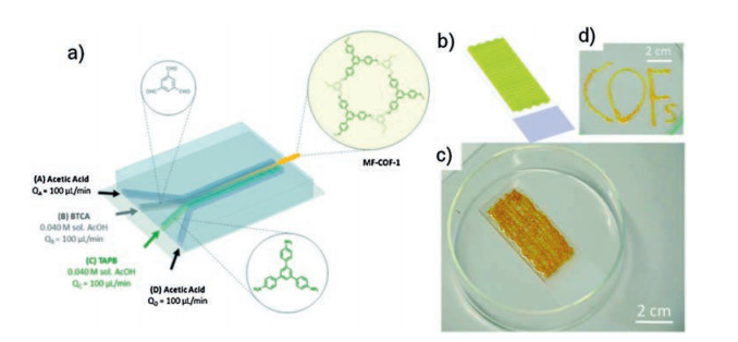
An imine-based COF was studied using the dynamic control over the mixing of reagents between 1, 3, 5-benzenetricarbaldehyde (BTCA) and 1, 3, 5-tris(4-aminophenyl)benzene (TAPB) under bulk chaotic mixing conditions [68, 69]. A greater degree of crystallinity of the resulting MF-COF-1 is favored, giving rise to the formation of jelly-like macroscopic fibres. As shown in Fig. 12, the microfluidic device used is comprised of four input channels leading to a main microfluidic channel, and the reaction can be controlled by varying the input flow rates of the reagent-laden flows (B and C) and the sheath flows (A and D). The resulting MF-COF possesses unique morphological features that are composed of meshes of fibres with macroporous sponge-like 3D branched structure. Due to the particular limited diffusion imposed during the microfluidic synthetic process, the fibres are formed by 40 nm particles anisotropically aggregated in a linear fashion. Furthermore, the microfluidic synthetic method enables the rapid synthesis of MF COF fibres at ambient temperature and pressure within a few seconds, which is possible to be employed as a printing tool to create complex two-or three-dimensional COF structures on different orientations and complex forms on surfaces.

|
Download:
|
| Fig. 12. Schematic illustration of (a) the microfluidic synthesis of MF-COF-1, (b) 3D printed network and (c, d) micrographs of the word "COFs" printed on glass. Copied with permission [68]. Copyright 2017, Journal of Visualized Experiments. | |
Continuous flow synthesis of COF-LZU1 with a production rate of 41 mg/h at an extremely high space-time yield of 703 kg m-3 day-1 was reported by Khan and co-workers [70]. Stock solutions of 1, 3, 5-triformylbenzene and 1, 4-phenylenediamine are injected together into a flow reactor, and the synthesis is conducted at room temperature with a residence time of 11 s. These COFs exhibit good crystallinity and high porosity comparable to their counterparts synthesized solvothermally at higher temperatures. The facile formation under mild synthetic conditions may be attributed to high solubility of monomers and the strong π-π stacking interactions between monomers and p-systems of oligomers. The resulting COF-LZU1 has a high BET surface area of 453 m2/g, possibly due to the improved crystallization process under flow conditions enabled by high local supersaturation at the interface between the two flowing streams.
COF-5 thin film formation has been adapted to a continuous flow process, which provides unprecedented control of film thickness while avoiding contamination by bulk COF powders [71]. Initially homogeneous monomer solutions polymerize while pumped through heated tubing for a given residence time, after which they pass over a substrate. While the monomers react slowly at 25 ℃ and condense to form COF-5 at 90 ℃, growth in flow is achieved by pumping the reaction mixture through a reservoir heated to 90 ℃. SEM indicates that films grown in flow are smoother and contaminated by fewer particulates over large areas. Moreover, COF films grown in flow exhibit constant rates of mass deposition, enabling thickness control as well as access to thicker films than are available from previous static growth procedures. Notably, the crystallinity of COF films is observed only at longer residence times, suggesting that oligomeric and polymeric species play an important role in forming the 2D COF lattice.
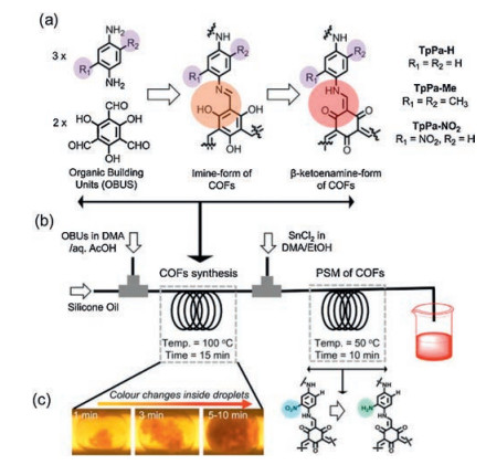
The continuous flow of microdroplets technique was used to realize intensified synthesis of β-ketoenamine-linked COFs (TpPa-H, TpPa-Me and TpPa-NO2) by using 1, 3, 5-triformylphloroglucinol (Tp) and 1, 4-phenylenediamine (Pa-H) as organic building units by Kim and co-workers (Fig. 13) [72]. Post-synthetic modification of TpPa-NO2 to TpPa-NH2 results in improved stability under varying chemical and thermal stresses compared to imine-and/or boronic acid-based COFs. This one-step synthesis serial microfluidic strategy avoids long separation and purification steps which may realize mass production of suitably functionalized COFs. To evaluate the applicability of the continuously synthesized COFs, Pd(OAc)2-loaded TpPa-H was adopted as an active catalyst in the Suzuki-Miyaura coupling reaction and biphenyl products were achieved in > 90% yields.

|
Download:
|
| Fig. 13. (a) Schematic representation of the synthesis of β-ketoenamine-linked COFs through initial imine formation and subsequent tautomerization; (b) The synthesis of the COFs (TpPa-H, TpPa-Me and TpPa-NO2) and serial post-synthetic modification of TpPa-NO2 to TpPa-NH2; (c) Monitoring of the 'in-droplet' reaction progress with a deep-red precipitate. Copied with permission [72]. Copyright 2018, Springer Nature. | |
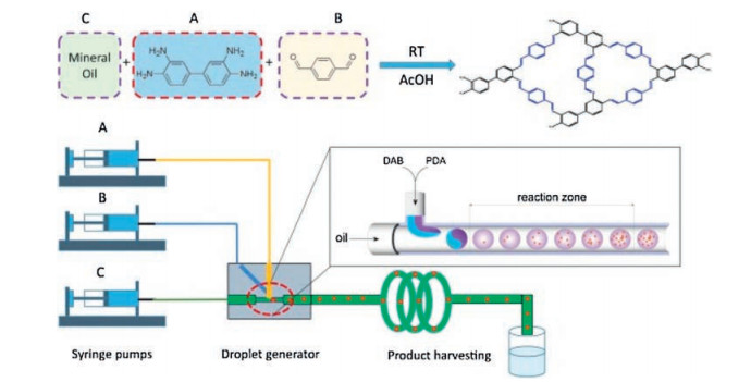
Polymorphous and hierarchical porous covalent organic poly-mer (COP) monoliths had been continuously synthesized via imine chemistry by Xiang and co-workers [73]. 3, 3-Diaminobenzidine and 1, 4-phthalaldehyde are mixed in droplet generator fabrication to form DP-COP monolith (Fig. 14). Its shape can vary from spherical to rod-like shape by simply changing the flow rate ratio between continuous flow and dispersive flow, which may satisfy the various requirements of catalyst packing density in industrial applications. The DP-COP particles tended to cluster together, formed large pores inside the products and gave the hierarchical porosity. It is considered to be an effective way to increase the catalyst's ability to diffuse and to enhance the distribution of active sites during catalyst preparation. The microreactor can produce spherical DP COP monolith with an estimated space-time yield of 413 kg m-3 day-1 in microfluidic system under optimized conditions.

|
Download:
|
| Fig. 14. Illustration of microfluidic setup and COP synthesis. Copied with permission [73]. Copyright 2019, Elsevier. | |
4. Continuous flow synthesis of porous organic cages
Continuous flow techniques have been also applied to regulate the synthesis of porous organic cages, although only one report has been demonstrated so far (Table 1). Unlike polymeric MOFs and COFs, porous organic cages are soluble in many common organic solvents, which allows their isolation to be decoupled from their synthesis, making them ideal candidates for flow chemistry. Synthesis of imine cage molecules in a flow reactor was reported by Cooper and coworkers [74]. CC1 and CC3-R are synthesized via a microfluidic reactor, and two porous organic cages share the same optimised conditions (0.62 mL/min R, R-1, 2-cyclohexanedi-amine (CHDA) (0.083 mol/L in CH2Cl2); 0.38 mL/min 1, 3, 5-trifor-mylbenzene (TFB) (0.083 mol/L in CH2Cl2); 10 min residence time; 100 ℃), which are opposed to batch synthesis conditions. By using the flow reactor to control the reactant ratio, it is able to produce scrambled cage mixtures, and running the flow reactor with a 1:5 ethylenediamine to CHDA ratio afforded the scrambled cage mixture with the greatest proportion of desymmetrised cage CC1135.
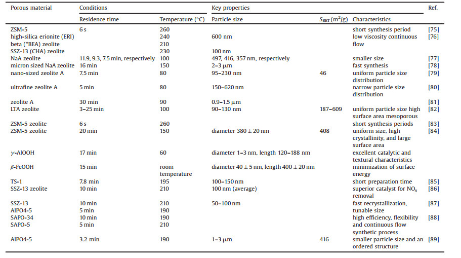
5. Continuous flow syntheses of zeolitesZeolites, a class of crystalline aluminosilicates, are the most widely used porous materials in industry. But the hydrothermal synthesis of zeolites has many disadvantages such as time-consuming and slow crystallization. The challenges of the continuous-flow synthesis of zeolites include slow crystallization, solid reactants and products. In addition, gelation of the polymerized and condensated (alumino)silicate species leads to sharp increase in viscosity. So far a number of microfluidic synthetic methods have also been reported for zeolites (Table 2) [75].
|
|
Table 2 Continuous flow synthesis of zeolites. |
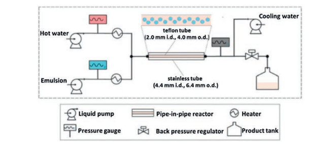
Segmented flow in continuous flow synthesis is of great help to the synthesis of zeolites. With the assistance of emulsion, the product suspensions flow out of the continuous flow reactor to overcome the viscosity challenge. Three industrially important zeolites, namely erionite (ERI), beta (*BEA) and chabazite (CHA) type zeolites were synthesized by Okubo, Wakihara and co-workers [76]. As shown in Fig. 15, the well-blended emulsion flows through a Teflon-lined pipe system, where a Teflon tube is putted inside a stainless steel tube to prevent the formation of solid phase from adhering to the reactor wall, and pressurized hot water is injected from the other inlet as a heating medium for rapid heating. The zeolite is obtained in the outlet because cyclohexane provides a segmented flow so that the product can flow out of the device. It is worth noting that the type and amount of surfactants can remarkably influence the local reaction environment, allowing change of grain size and possibly altering the crystallization process of zeolites.

|
Download:
|
| Fig. 15. Flowchart of the continuous flow synthesis of ERI zeolite where a Teflon tube is placed inside a stainless steel tube. Copied with permission [76]. Copyright 2018, Royal Society of Chemistry. | |
Continuous synthesis of zeolite NaA was developed in a stainless steel microchannel reactor by Zhang and co-workers [77]. Firstly, the silicate solution is added to the aluminate solution. After aging of the synthesis solution (about 6 d) to avoid the blockage of the reactor, the synthesis mixture is vigorously stirred for 2 h. Then the synthesis solution is injected into the stainless steel microchannel reactor for the continuous synthesis of zeolite NaA. The crystallization time required to synthesize zeolite NaA with good crystallinity in the microchannel reactor is significantly reduced to one tenth compared to what is required in the batch system. On the other hand, the average particle size (357 nm) and particle size distribution (310-400 nm) of zeolite NaA synthesized by the microchannel reactor are smaller and narrower than the batch system, respectively. It is worth noting that the zeolite NaA synthesized at high temperature has a short residence time and a large average particle size, while narrow particle size distribution, which is caused by the rapid heat transfer and the auto-creation segmentation flow of the synthesis solution in the microchannel reactor.
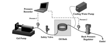
A pilot scale continuous-flow reactor was used for the rapid synthesis of NaA zeolite crystals by De Malsche and co-workers [78]. The Si/Al precursor gel is fed into a stainless steel reaction tube submerged in the circulating oil, and the temperature inside the reaction tube can be controlled by a constant-flow pump of the thermostat (Fig. 16). After the solution flows through another stainless steel coil immersed in cold water to cool the fluid/gel to room temperature, NaA zeolite can be obtained under a constant pressure of 5 bar by using a pressurized air cylinder. Because of its high specific surface area, this continuous-flow reactor has many advantages such as accelerating of heat transfer and mass transfer, quick changing of temperature in the liquid during heating and cooling, reducing of residence time and thermal lag. Therefore, the NaA zeolite is crystallized quickly and controllably. With an ideal synthesis environment acquired by using the continuous flow reactor, the NaA zeolite is yielded at 160 g/h per liter reactor volume in 16 min. In comparison, the batch process produces 33 g/h per liter reactor volume and it performs 10 times slower than in the continuous-flow reactor. In the continuous-flow reactor, the precursor gel can be heated or cooled down to a specified temperature in a few seconds, and the synthetic process can be stopped almost immediately. The risk of clogging is reduced a lot yielding maximal productivity without impurities.

|
Download:
|
| Fig. 16. Flowchart of the continuous-flow reactor setup for the rapid synthesis of NaA zeolite. Copied with permission [78]. Copyright 2016, Elsevier. | |
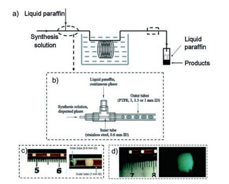
A synthetic strategy to ultrafine zeolite A crystals with LTA (Linde Type A) structure with narrow particle size distribution was developed using water-liquid paraffin two-phase segmented microfluidic reactors by Zhang and co-workers [79]. The synthesis solution (as a dispersed phase) is injected into the inner tube by a constant flow pump, and the liquid paraffin (as a continuous phase) is transported to the outer tube immersed in an oil bath by a piston pump to obtain zeolite A crystals (100-240 nm) with well-developed crystal faces (Fig. 17). The crystallization time, mean particle sizes and narrow particle size distribution of zeolite A can be controlled by adjusting the aging of the synthesis solution, the temperature and the sizes of the outer tube. The rate of crystallization in the segmented microfluidic reactor is slightly slower than that in the microwave-heated batch reactor, but is significantly higher than those in the conventional batch reactor and single-phase microfluidic reactor. Meanwhile, in comparison with products synthesized in the conventional batch reactor, single-phase microfluidic reactor, and microwave-heated reactor, the zeolite A crystals produced in the segmented microfluidic device have smaller particle sizes and narrower particle size distribution. The same group also synthesized uniform sized zeolite A nanocrystals in a two-phase liquid segmented microfluidic reactor by using manipulated organic template-free zeolite A synthesis solutions [80]. Firstly, synthesis solutions are prepared by adding silica clear solution, silica-alumina clear solution or alumina clear solution into the milky gel solution, then they are pumped into a stainless steel capillary microreactor to obtain uniform sized zeolite A nanocrystals with mean particle sizes of 408 and 262 nm and particle size distributions of 150-620 nm and 100-420 nm.

|
Download:
|
| Fig. 17. Scheme of a two-phase liquid segmented microfluidic system and flow patterns in the reaction tube for zeolite A synthesis. (a) General flowchart; (b) Detailed illustration of the coaxial dual pipe assembly; (c) View of flow patterns at the outlet of the inner tube; (d) View of flow patterns at the outlet of the outer tube. Copied with permission [79]. Copyright 2009, Royal Society of Chemistry. | |
One-step continuous synthesis of zeolite A crystals using the silica and alumina solutions as the raw materials to form the hydrogel micro-droplets in a continuous paraffin phase segmented microfluidic device was also presented by Zhang and co-workers [81]. Firstly, silica solutions and alumina solutions are pumped into the PTFE inner tubes and hydrogel droplets are formed in the microfluidic reactor, then the synthesis of zeolite A occurs in the PTFE outer tube. The nucleation process and the crystallization process can be controlled separately by change of the length and temperature. By changing the velocity ratios of the silica to alumina solutions, the composition of the gel synthesis solution can be conveniently adjusted, obtaining versatile synthesis of zeolite A crystals having different particle sizes with the range of 0.9-1.5 μm and different crystallinities. Reducing the dimension of outer tube or ultrasonic radiation can reduce the sizes of hydrogel segments, thereby increasing the mixing efficiency, intensifying the heat and mass transfer rate, accelerating the crystallization rate, and subsequent forming high crystalline zeolite A crystals. This one-step continuous synthesis method not only avoids the difference between product batches, but also reduces the cost of large-scale zeolite synthesis.
A microfluidic system consisting of a lab-on-a-chip part for droplet generation and capillary tube part was designed and used for the hydrothermal synthesis of zeolite A by Kim and co-workers, where the precursor solution was dispersed into monodisperse nanolitre droplets (Fig. 18) [82]. The aqueous droplets encapsulated in oil medium prevent the growing nanocrystals from contacting the microchannel wall, thus preventing channel clogging, which opens an avenue for producing high quality inorganic nanoparticles continuously. Moreover, the hierarchically mesoporous-microporous zeolite A crystals with high surface areas (609 m2/g) and uniform particle size around 100 nm are synthesized by addition of water-soluble alginate polymer as a pore-expanding agent into the gel precursor solution, presenting excellent catalytic activity in the synthesis of alkylborate with higher conversion yields and improved stability.

|
Download:
|
| Fig. 18. (a) Schematic diagram of the droplet microfluidic system composed of a lab-on-a-chip fluoropolymer part and capillary tube part; (b) optical image of the zeolite precursor solution droplets in the fluoropolymer device. The scale bar is 500 mm. Copied with permission [82]. Copyright 2012, Royal Society of Chemistry. | |
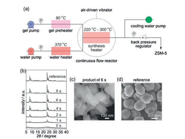
The continuous flow synthesis of ZSM-5 with MFI structure on the order of seconds was reported by Wakiharaa and co-workers[83]. A water heater full of pressurized hot water with extremely high temperature (370 ℃) and the gel precursor obtained by aging the initial aluminosilicate gel at 90 ℃ for 16 h are already prepared in advance. Then the pressurized hot water in a millimeter-sized continuous flow reactor results in immediate heating of the gel up to high temperature (220-300 ℃) (Fig. 19). Consequently, the fully crystalline ZSM-5 with a particle size of around 20 mm without the addition of any seed can be obtained in 6 s with a very high space-time yield (~7000 kg m-3 h-1).

|
Download:
|
| Fig. 19. (a) Flowchart for the continuous flow synthesis of ZSM-5. (b) XRD patterns for the products synthesized over different periods at 260 ℃ (the reference ZSM-5 was synthesized in a conventional autoclave at 170 ℃ for 24 h. (c, d) SEM images for the ZSM-5 product synthesized in 6 s at 260 ℃ and the reference ZSM-5, respectively. Copied with permission [83]. Copyright 2016, National Academy of Sciences. | |
ZSM-5 was also synthesized using a droplet and ionic liquid-assisted microfluidic (DIM) synthesis method from a mixed precursor solution [84]. ZSM-5 shows irregular shape, wider size distribution and lower crystallinity in the case of continuous microreactor systems without droplet generators. It is worth noting that a DIM process integrated by ionic liquids and droplet microfluidics induces the uniform and high crystalline zeolite nanoparticles (380 20 nm) by effectively regulating their growth even with simple instrumentation. The resulting ZSM-5 shows 53.6% and 71.8% conversion yields of benzaldehyde when reacted with 1-butanol and glycol, respectively, which are significantly higher than 30.4% and 52.9% yielded by the conventional ZSM-5.
Ultrafast synthesis of TS-1 (MFI structure) nanoparticles with all Ti species existing in the tetrahedral coordination state was achieved in a continuous-flow system by Luo and co-workers [85]. The precursor solution is obtained by mixing tetraethyl orthosi-licate, tetra-butyl orthotictanate and tetrapropylammonium hy-droxide, then it is pumped into the stainless steel tubular reactor to obtain the products, and finally the synthetic products are calcined in air to obtain TS-1 products. The TS-1 nanoparticles grown with a continuous-flow system exhibit significantly higher energy utilization and shorter crystallization time than batch reactors, suggesting that the tubular reactor plays a crucial role in the fast heating rate and uniform experimental environment. This possibly increases the proportion of titanium into the silicon skeleton, and almost all titanium species existing in the tetrahedral coordination state have a grain size of 42 nm.
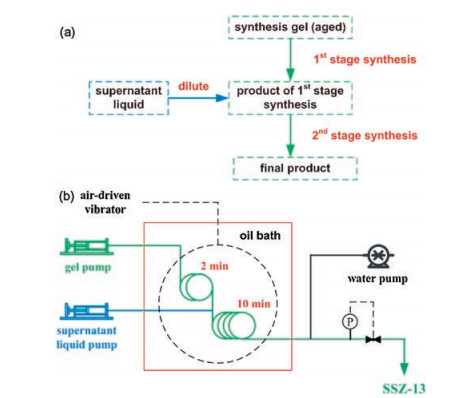
SSZ-13 (CHA topology) is a zeolite which can be used as a catalyst for conversion of nitrogen oxides, methanol-to-olefins reaction and other reactions. With the help of added SSZ-13 seed ultrafast continuous-flow synthesis of SSZ-13 could complete in 10 min compared with the typical method in Teflon-lined autoclaves (more than 6 d) [86]. A two-stage synthesis method is developed to overcome the viscosity problem of the reaction mixture in which the gel is diluted with a supernatant liquid in the middle of the process (Fig. 20). An air-driven vibrator is used to improve the mixing of the supernatant liquid as well as to prevent precipitation inside the flow reactor. This design allows a smooth continuous synthesis without any blockage problem. In addition, continuous-flow recrystallization is established with the slurry of milled SSZ-13 fed into a stainless steel flow reactor [87]. Nanosized SSZ-13 is obtained within a short residence time of 10 min under high temperature to avoid the blockage.

|
Download:
|
| Fig. 20. (a) Scheme of the procedure for two-stage continuous-flow synthesis; (b) Flow chart for the continuous-flow preparation of SSZ-13. Copied with permission [86]. Copyright 2015, Wiley-VCH. | |
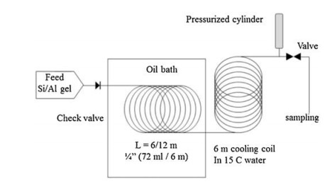
Phosphate-based zeolites include aluminophosphates and silicoaluminophosphates. SAPO CHA (also called SAPO-34) and SAPO-AFI (also called SAPO-5) are two representative structures of silicoaluminophosphates. AlPO4-5 (AFI-topology) silicoalumino-phosphates are generated by incorporation of Si atoms into the framework of aluminophosphates. An ultrafast synthesis route for the preparation of crystalline microporous aluminophosphate material AlPO4-5 by combining fast heating provided by continu-ous-flow synthesis with a seed-assisted method skipping spontaneous nucleation was achieved by Okubo and co-workers [88]. The Al source gel containing the AlPO4-5 seed is fed into the stainlesssteel tube, which is sealed and immersed in an oil bath under a certain pressure and temperature to achieve ultrafast and continuous flow synthesis of aluminophosphate (Fig. 21). AlPO4-5 crystals synthesized by the continuous flow reactor possess well-controlled morphology like a smaller particle size of about 1 mm and an ordered structure of parallel needle-like crystals due to the rapid heating and uniform crystallization environment. In addition, using the product in the continuous flow reactor as seeds, AlPO4-5 crystals with analogous morphology are obtained, indicating good reusability which can avoid the long time reaction required for the preparation of seed using a conventional autoclave.

|
Download:
|
| Fig. 21. Schematic diagram of the continuous synthesis system for AlPO4-5. Copied with permission [88]. Copyright 2014, American Chemical Society. | |
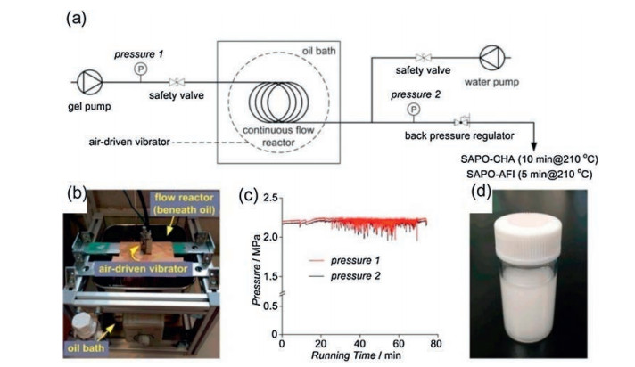
SAPO-CHA and SAPO-AFI were also rapidly synthesized in a tubular reactor with a continuous flow process by Okubo and co-workers [89]. The Al and Si source precursor containing the milled SAPO-CHA seed is pumped into the tubular reactor, which is sealed and immersed in an oil bath preheated to a certain temperature to achieve ultrafast and continuous flow synthesis of silicoaluminophosphates (Fig. 22). The fast-synthesized SAPO-CHA have only isolated Si(OAl)4 species without Si islands, indicating great potential as an excellent catalyst because of high hydrothermal stability and appropriate acidity. In addition, due to the characteristics of rapid heating, the tubular reactor proved itself to be a facile and accurate platform for controlling the phase selection between SAPO-CHA and SAPO-AFI by regulating the crystallization kinetics, which could not be achieved in conventional autoclaves.

|
Download:
|
| Fig. 22. Continuous flow synthesis of silicoaluminophosphates. (a) Diagram of the continuous flow synthesis of silicoaluminophosphates. (b) Photograph of the oil bath and the flow reactor immersed therein. (c) Pressure log showing the synchronized fluctuation of the pressures at both ends of the flow reactor. (d) Photograph of the milky slurry flowing out of the flow reactor. Copied with permission [89]. Copyright 2016, American Chemical Society. | |
6. Conclusions and outlooks
In summary, a wide range of porous materials have been developed using microfluidic, or flow chemistry techniques. To date, a number of crystalline porous materials such as MOFs, COFs, porous organic cages and zeolites have been investigated in detail and their synthetic methods have been developed under micro-fluidic conditions. Traditional synthetic methods generally require high temperature and high pressure, but microfluidic synthesis can make the synthetic conditions less harsh. Certain porous materials can be prepared ultrafast by continuous flow synthesis compared to other synthetic methods, which can even reach nearly several seconds. In addition, porous materials with good crystallinity, high porosity, high stability, controllable particle size, high specific surface area and high space-time yield can be prepared by continuous flow synthetic methods. Microfluidic synthesis pro-vides an efficient approach for the preparation of the porous materials. Despite the relative immaturity of the method, the microfluidic synthesis of porous materials is demonstrating enormous promise.
The microfluidic techniques of organic porous materials (COFs and porous organic cages) have been far less developed although significant progress has been made in MOFs and zeolites. In the future, reducing the energy consumption of the synthesis process, such as reducing the reaction time and lowering the reaction temperature, may play an important role in the synthetic field. Continuous flow synthesis methods have shown great advantages in comparison with other methods in preparing porous materials, however, the combination of continuous flow techniques with other methods also offer considerable potential in the synthesis of porous materials. Microfluidic techniques can be combined with different heating ways. For example, synthetic methods combining microfluidic and microwave assisted heating have been developed for several MOFs as shown above, because microwave-assisted continuous flow techniques is an effective method of heating which has benefits such as significantly reducing production times (from hours to minutes), increasing product yield and purity, and improving product properties. Microfluidic reactors can be changed by different methods of substrate adding which can increase mixing intensity and provide more uniform reaction conditions, such as central collision-type reactor with short diffusion distance and jet-mixing reactor using the kinetic energy of introduced impinging jet-streams as shown. With the fast development of flow chemistry techniques, it is expected that continuous flow synthetic method and their combination with porous materials will show great potential and continue to be a rich area of research moving forward.
Declaration of competing interestThe authors declare that they have no known competing financial interests or personal relationships that could have appeared to influence the work reported in this paper.
AcknowledgmentsWe gratefully acknowledge the National Natural Science Foundation of China (NSFC, No. 51573216) and the NSF of Guangdong Province for financial support.
| [1] |
G. Li, S. Zhao, Y. Zhang, Z. Tang, Adv. Mater. 30 (2018) 1800702. DOI:10.1002/adma.201800702 |
| [2] |
M.M. Sadiq, K. Suzuki, M.R. Hill, Chem. Commun. 54 (2018) 2825-2837. DOI:10.1039/C8CC00331A |
| [3] |
J. Zhang, J. Chen, S. Peng, et al., Chem. Soc. Rev. 48 (2019) 2566-2595. DOI:10.1039/C8CS00657A |
| [4] |
H. Wang, Z. Zeng, P. Xu, et al., Chem. Soc. Rev. 48 (2019) 488-516. DOI:10.1039/C8CS00376A |
| [5] |
N. Stock, S. Biswas, Chem. Rev. 112 (2012) 933-969. DOI:10.1021/cr200304e |
| [6] |
N.A. Khan, S.H. Jhung, Coord. Chem. Rev. 285 (2015) 11-23. DOI:10.1016/j.ccr.2014.10.008 |
| [7] |
H. Al-Kutubi, J. Gascon, E.J.R. Sudhölter, L. Rassaei, ChemElectroChem 2 (2015) 462-474. DOI:10.1002/celc.201402429 |
| [8] |
S.L. James, C.J. Adams, C. Bolm, et al., Chem. Soc. Rev. 41 (2012) 413-447. DOI:10.1039/C1CS15171A |
| [9] |
L. Garzón-Tovar, M. Cano-Sarabia, A. Carné-Sánchez, et al., React. Chem. Eng. 1 (2016) 533-539. DOI:10.1039/C6RE00065G |
| [10] |
P. Pal, J.K. Das, N. Das, S. Bandyopadhyay, Ultrason. Sonochem. 20 (2013) 314-321. DOI:10.1016/j.ultsonch.2012.07.012 |
| [11] |
Rubio-Martinez M., Avci-Camur C., A.W. Thornton, et al., Chem. Soc. Rev. 46 (2017) 3453-3480. DOI:10.1039/C7CS00109F |
| [12] |
S. Sevim, A. Sorrenti, C. Franco, et al., Chem. Soc. Rev. 47 (2018) 3788-3803. DOI:10.1039/C8CS00025E |
| [13] |
V. Sebastian, S.A. Khan, A.A. Kulkarni, J. Flow Chem. 7 (2017) 96-105. DOI:10.1556/1846.2017.00028 |
| [14] |
M.B. Plutschack, B. Pieber, K. Gilmore, P.H. Seeberger, Chem. Rev. 117 (2017) 11796-11893. DOI:10.1021/acs.chemrev.7b00183 |
| [15] |
R.M. Myers, D.E. Fitzpatrick, R.M. Turner, S.V. Ley, Chem. Eur. J. 20 (2014) 12348-12366. DOI:10.1002/chem.201402801 |
| [16] |
J. Britton, T.F. Jamison, Nat. Protocols 12 (2017) 2423-2446. DOI:10.1038/nprot.2017.102 |
| [17] |
P.W. Dunne, E. Lester, R.I. Walton, React. Chem. Eng. 1 (2016) 352-360. DOI:10.1039/C6RE00107F |
| [18] |
J. Wang, Y. Song, Small 13 (2017) 1604084. DOI:10.1002/smll.201604084 |
| [19] |
L. Shang, Y. Cheng, Y. Zhao, Chem. Rev. 117 (2017) 7964-8040. DOI:10.1021/acs.chemrev.6b00848 |
| [20] |
X. Gong, W. Wen, P. Sheng, Langmuir 25 (2009) 7072-7077. DOI:10.1021/la900120c |
| [21] |
R.L. Hartman, J.P. McMullen, K.F. Jensen, Angew. Chem. Int. Ed. 50 (2011) 7502-7519. DOI:10.1002/anie.201004637 |
| [22] |
J. Britton, C.L. Raston, Chem. Soc. Rev. 46 (2017) 1250-1271. DOI:10.1039/C6CS00830E |
| [23] |
D. Zhao, K. Ding, ACS Catal. 3 (2013) 928-944. DOI:10.1021/cs300830x |
| [24] |
C.G. Frost, L. Mutton, Green Chem. 12 (2010) 1687-1703. DOI:10.1039/c0gc00133c |
| [25] |
D. Cantillo, C.O. Kappe, ChemCatChem 6 (2014) 3286-3305. DOI:10.1002/cctc.201402483 |
| [26] |
W. Zhan, M. Tong, L. Ji, et al., Chin. Chem. Lett. 30 (2019) 973-976. DOI:10.1016/j.cclet.2019.01.006 |
| [27] |
Y. Wu, W.Q. Chen, Y.Q. Zhao, H.R. Piao, Chin. Chem. Lett. 26 (2015) 334-338. DOI:10.1016/j.cclet.2014.11.013 |
| [28] |
J. Zhang, C. Gong, X. Zeng, J. Xie, Coord. Chem. Rev. 324 (2016) 39-53. DOI:10.1016/j.ccr.2016.06.011 |
| [29] |
A.M. Nightingale, J.C. deMello, Adv. Mater. 25 (2013) 1813-1821. DOI:10.1002/adma.201203252 |
| [30] |
M. Gonidec, J. Puigmartí-Luis, Crystals 9 (2019) 12. |
| [31] |
A. Ufer, M. Mendorf, A. Ghaini, D.W. Agar, Chem. Eng. Technol. 34 (2011) 353-360. DOI:10.1002/ceat.201000334 |
| [32] |
L.B. Matyushkin, R.C. Mbwahnche, O.A. Ryzhov, J. Phys. Conf. Ser. 769 (2016) 012035. DOI:10.1088/1742-6596/769/1/012035 |
| [33] |
J.B. Wacker, I. Lignos, V.K. Parashar, M.A.M. Gijs, Lab Chip 12 (2012) 3111-3116. DOI:10.1039/c2lc40300e |
| [34] |
T.N. Ng, X.Q. Chen, K.L. Yeung, RSC Adv. 5 (2015) 13331-13340. DOI:10.1039/C4RA16679E |
| [35] |
S.A. Khan, K.F. Jensen, Adv. Mater. 19 (2007) 2556-2560. DOI:10.1002/adma.200700127 |
| [36] |
L. Paseta, B. Seoane, D. Julve, et al., ACS Appl. Mater. Inter. 5 (2013) 9405-9410. DOI:10.1021/am4029872 |
| [37] |
G.Y. Jeong, R. Ricco, K. Liang, et al., Chem. Mater. 5 (2015) 7903-7909. |
| [38] |
P.A. Bayliss, I.A. Ibarra, E. Perez, et al., Green Chem. 16 (2014) 3796-3802. DOI:10.1039/C4GC00313F |
| [39] |
M. Rubio-Martinez, T.D. Hadley, M.P. Batten, et al., ChemSusChem 9 (2016) 938-941. DOI:10.1002/cssc.201501684 |
| [40] |
M. Taddei, D.A. Steitz, J.A. van Bokhoven, M. Ranocchiari, Chem. Eur. J. 22 (2016) 3245-3249. DOI:10.1002/chem.201505139 |
| [41] |
S.R. Jambovane, S.K. Nune, R.T. Kelly, et al., Sci. Rep. 6 (2016) 36657. DOI:10.1038/srep36657 |
| [42] |
S. Waitschat, M.T. Wharmby, N. Stock, Dalton Trans. 44 (2015) 11235-11240. DOI:10.1039/C5DT01100K |
| [43] |
Y. Wang, L. Li, P. Dai, et al., J. Mater. Chem. A 5 (2017) 22372-22379. DOI:10.1039/C7TA06060B |
| [44] |
M. Taddei, N. Casati, D.A. Steitz, et al., CrystEngComm 19 (2017) 3206-3214. DOI:10.1039/C7CE00867H |
| [45] |
S. Tai, W. Zhang, J. Zhang, et al., Microporous Mesoporous Mater. 220 (2016) 148-154. DOI:10.1016/j.micromeso.2015.08.037 |
| [46] |
L. Garzon-Tovar, M. Cano-Sarabia, A. Carne-Sanchez, et al., React. Chem. Eng. 1 (2016) 533-539. |
| [47] |
M. Rubio-Martinez, M.P. Batten, A. Polyzos, et al., Sci. Rep. 4 (2014) 5443-5448. |
| [48] |
Y. Wang, L. Li, L. Yan, et al., Chin. Chem. Lett. 29 (2018) 849-853. DOI:10.1016/j.cclet.2017.09.057 |
| [49] |
Y. Wang, L. Li, L. Yan, et al., Chem. Mater. 30 (2018) 3048-3059. DOI:10.1021/acs.chemmater.8b00765 |
| [50] |
A. Polyzoidis, T. Altenburg, M. Schwarzer, S. Loebbecke, S. Kaskel, Chem. Eng. J. 283 (2016) 971-977. DOI:10.1016/j.cej.2015.08.071 |
| [51] |
O. Kolmykov, J.M. Commenge, H. Alem, et al., Mater. Des. 122 (2017) 31-41. DOI:10.1016/j.matdes.2017.03.002 |
| [52] |
S. Watanabe, S. Ohsaki, T. Hanafusa, et al., Chem. Eng. J. 313 (2017) 724-733. DOI:10.1016/j.cej.2016.12.118 |
| [53] |
A. Parulkar, N.A. Brunelli, Ind. Eng. Chem. Res. 56 (2017) 10384-10392. DOI:10.1021/acs.iecr.7b02849 |
| [54] |
A.S. Munn, P.W. Dunne, S.V.Y. Tang, E.H. Lester, Chem. Commun. 51 (2015) 12811-12814. DOI:10.1039/C5CC04636J |
| [55] |
G. Hu, L. Yang, Y. Li, L. Wang, J. Mater. Chem. B 6 (2018) 7936-7942. DOI:10.1039/C8TB02308E |
| [56] |
M.P. Batten, M. Rubio-Martinez, T. Hadley, et al., Curr. Opin. Chem. Eng. 8 (2015) 55-59. DOI:10.1016/j.coche.2015.02.001 |
| [57] |
A. Laybourn, A.M. López-Fernández, I. Thomas-Hillman, et al., Chem. Eng. J. 356 (2019) 170-177. DOI:10.1016/j.cej.2018.09.011 |
| [58] |
M. Gimeno-Fabra, A.S. Munn, L.A. Stevens, et al., Chem. Commun. 48 (2012) 10642-10644. DOI:10.1039/c2cc34493a |
| [59] |
R. Ameloot, F. Vermoortele, W. Vanhove, et al., Nat. Chem. 3 (2011) 382-387. DOI:10.1038/nchem.1026 |
| [60] |
K.J. Kim, Y.J. Li, P.B. Kreider, et al., Chem. Commun. 49 (2013) 11518-11520. DOI:10.1039/c3cc46049e |
| [61] |
A. Carne-Sanchez, I. Imaz, M. Cano-Sarabia, D. Maspoch, Nat. Chem. 5 (2013) 203-211. DOI:10.1038/nchem.1569 |
| [62] |
K.-J. Kim, Y.J. Li, P.B. Kreider, et al., Chem. Commun. 49 (2013) 11518-11520. DOI:10.1039/c3cc46049e |
| [63] |
T. Didriksen, A.I. Spjelkavik, R. Blom, J. Flow Chem. 7 (2017) 13-17. DOI:10.1556/1846.2016.00040 |
| [64] |
C. McKinstry, R.J. Cathcart, E.J. Cussen, et al., Chem. Eng. J. 285 (2016) 718-725. DOI:10.1016/j.cej.2015.10.023 |
| [65] |
L. D'Arras, C. Sassoye, L. Rozes, et al., New J. Chem. 38 (2014) 1477-1483. DOI:10.1039/C3NJ01371E |
| [66] |
H. Reinsch, S. Waitschat, S.M. Chavan, K.P. Lillerud, N. Stock, Eur. J. Inorg. Chem. 2016 (2016) 4490-4498. DOI:10.1002/ejic.201600295 |
| [67] |
M. Faustini, J. Kim, G.Y. Jeong, et al., J. Am. Chem. Soc. 135 (2013) 14619-14626. DOI:10.1021/ja4039642 |
| [68] |
A. Abrishamkar, D. Rodríguez-San-Miguel, J.A.R. Navarro, et al., J. Vis. Exp. (2017) e56020. |
| [69] |
D. Rodríguez-San-Miguel, A. Abrishamkar, J.A.R. Navarro, et al., Chem. Commun. 52 (2016) 9212-9215. DOI:10.1039/C6CC04013F |
| [70] |
Y. Peng, W.K. Wong, Z. Hu, et al., Chem. Mater. 28 (2016) 5095-5101. DOI:10.1021/acs.chemmater.6b01954 |
| [71] |
R.P. Bisbey, C.R. DeBlase, B.J. Smith, W.R. Dichtel, J. Am. Chem. Soc. 138 (2016) 11433-11436. DOI:10.1021/jacs.6b04669 |
| [72] |
V. Singh, S. Jang, N.K. Vishwakarma, D.P. Kim, NPG Asia Mater. 10 (2018) e456. DOI:10.1038/am.2017.209 |
| [73] |
Y. Zhao, Z. Liao, Z. Xiang, Chem. Eng. Sci. 195 (2019) 801-809. DOI:10.1016/j.ces.2018.10.026 |
| [74] |
M.E. Briggs, A.G. Slater, N. Lunt, et al., Chem. Commun. 51 (2015) 17390-17393. DOI:10.1039/C5CC07447A |
| [75] |
Z. Liu, J. Zhu, T. Wakihara, T. Okubo, Inorg. Chem. Front. 6 (2019) 14-31. DOI:10.1039/C8QI00939B |
| [76] |
J. Zhu, Z. Liu, Y. Yonezawa, et al., React. Chem. Eng. 3 (2018) 844-848. DOI:10.1039/C8RE00139A |
| [77] |
J. Ju, C. Zeng, L. Zhang, N. Xu, Chem. Eng. J. 116 (2006) 115-121. DOI:10.1016/j.cej.2005.11.006 |
| [78] |
T. Vandermeersch, T.R.C. Van Assche, J.F.M. Denayer, W. De Malsche, Microporous Mesoporous Mater. 226 (2016) 133-139. DOI:10.1016/j.micromeso.2015.12.039 |
| [79] |
Y. Pan, M. Ju, J. Yao, L. Zhang, N. Xu, Chem. Commun. (2009) 7233-7235. |
| [80] |
Y. Pan, J. Yao, L. Zhang, N. Xu, Ind. Eng. Chem. Res. 48 (2009) 8471-8477. DOI:10.1021/ie900621y |
| [81] |
L. Yu, Y. Pan, C. Wang, L. Zhang, Chem. Eng. J. 219 (2013) 78-85. DOI:10.1016/j.cej.2013.01.009 |
| [82] |
P.H. Hoang, K.B. Yoond, D.P. Kim, RSC Adv. 2 (2012) 5323-5328. DOI:10.1039/c2ra20074k |
| [83] |
Z. Liu, K. Okabe, C. Anand, et al., Proc. Natl. Acad. Sci. U. S. A. 113 (2016) 14267-14271. DOI:10.1073/pnas.1615872113 |
| [84] |
P.H. Hoang, H.S. Park, D.-P. Kim, J. Am. Chem. Soc. 133 (2011) 14765-14770. DOI:10.1021/ja2054429 |
| [85] |
Y. Hu, K. Wang, T. Wang, G. Luo, Microporous Mesoporous Mater. 270 (2018) 149-154. DOI:10.1016/j.micromeso.2018.04.043 |
| [86] |
Z. Liu, T. Wakihara, K. Oshima, et al., Angew. Chem. Int. Ed. 54 (2015) 5683-5687. DOI:10.1002/anie.201501160 |
| [87] |
Z. Liu, N. Nomura, D. Nishioka, et al., Chem. Commun. 51 (2015) 12567-12570. DOI:10.1039/C5CC04542H |
| [88] |
Z. Liu, T. Wakihara, D. Nishioka, et al., Chem. Mater. 26 (2014) 2327-2331. DOI:10.1021/cm500287g |
| [89] |
Z. Liu, T. Wakihara, N. Nomura, et al., Chem. Mater. 28 (2016) 4840-4847. DOI:10.1021/acs.chemmater.6b02141 |