 2020, Vol. 31


b Institute of Zhejiang University-Quzhou, Quzhou 324000, China;
c State Key Laboratory of Silicon Materials, School of Materials Science and Engineering, Zhejiang University, Hangzhou 310027, China;
d Ability R&D Energy Research Centre(AERC), School of Energy and Environment, City University of Hong Kong, Hong Kong 999077, China;
e Ningbo Research Institute, Zhejiang University, Ningbo 315100, China
The continuously increased factitious emission of CO2 have caused markedly temperature rising and various environment problems [1]. To curb this trend, it is the top priority to convert superfluous CO2 in the atmosphere to value-add chemicals, and electrochemical CO2 reduction is one of the most promising strategies to realize the conversion in mild conditions with renewable-energy electricity [2]. However, considering that CO2 molecule is tough to accept electron due to extremely stable chemical bonds, it is the key issue to develop suitable and efficient electrocatalysts to realize CO2 reduction reaction (CRR).
To date, nanocarbon materials have attracted extensive attention as low cost and highly efficient electrocatalysts owing to their flexible surface modification, large geometrical surface area, and admirable thermal conductivity [3], especially for typical one-dimensional (1D) carbon nanotubes (CNTs) and two-dimensional (2D) graphene nanosheets [4]. However, these nanocarbons materials tend to aggregate because of the irreversible van der Waals forces, which can result in the loss of active surface areas and catalytic active sites, suppressing efficient electrocatalytic reactions [5]. Of note is that, integrating graphene and CNTs to from a unique one-dimensional (3D) hybrid nanocarbon architecture is recently emerged as an alternative strategy to address the aggregation problems, because the inserted CNTs can greatly optimize the dispersion of graphene associated with an enhanced surface-to-volume ratio [6], and the formed 3D hybrid carbon network can efficiently enhance the electron transfer and thermal conductivity [7]. Hitherto, several attempts on design of 3D hybrid carbon nanostructures have been reported and their various electrochemical applications with intriguing properties, such as lithium ion batteries [8], supercapacitors [6], oxygen reduction reaction [5], have been demonstrated.
Up to now, although tremendous efforts have been devoted to construct such 3D hybrid nanocarbons, most of these are limited to chemical vapor deposition strategies [7], or spin-coating and self-assembly strategies via surface-functionalization technique [9]. Unfortunately, these fabrication routes usually suffer from severe obstacles, including complex multistage procedure, expensive machineries, and low yields, especially the weak bonding between graphene and CNTs, largely limiting their industrial applications [10]. In addition, it'sworth noting that the CNTs with encapsulated metal nanoparticles (NPs) has been recently proposed and reported to be highly efficient electrocatalysts because it not only induce additional catalytic active sites but also create high graphitic degree. Such unique property of CNTs with encapsulated metal NPs could provide a wide platform for exploring desirable multifunctional properties, which have been reported for CRR catalysis [11]. Therefore, it is desirable to develop a facile and efficient strategy to construct a fancy 3D hybrid nanocarbon electrocatalyst by strongly assembling Ni NPs, CNTs, and graphene to boost the catalytic performance for CRR.
In this work, we designed a novel 3D N-doped CNT-encapsulated Ni NPs supported on graphene (N/NiNPs@CNT/G) hybrid by pyrolyzing the mixture of graphene, nickel salt, and polymeric dicyandiamide as N source. The 3D hybrid structure was composed of Ni NPs sized below 100 nm that are encapsulated by several carbon layers, formed countable CNTs supported on graphene, and doped N species up to 7.27 at%. Thanks to the encapsulated Ni NPs and abundant N dopants, the resulting N/NiNPs@CNT/G hybrid could meaningfully enhance CRR activity with a remarkable CO Faradaic efficiency (FE) of 97.7% and a large CO partial current density of 7.9 mA/cm2 at 0.7 V. Such high CRR performance was comparable to that of most reported metallic NPs loaded carbon based electrocatalysts (Table S1 in Supporting information). In addition, the CO FE maintained over 90% and the current density displayed a negligible decay in continuous operation over 10 h, indicating high stability of N/NiNPs@CNT/G. Systematic characterizations coupled with electrochemical obser-vations revealed that the Ni NPs significantly contributed to the enhanced electrocatalytic activity for CRR and the dispersed N dopants accounted for the improved current density.
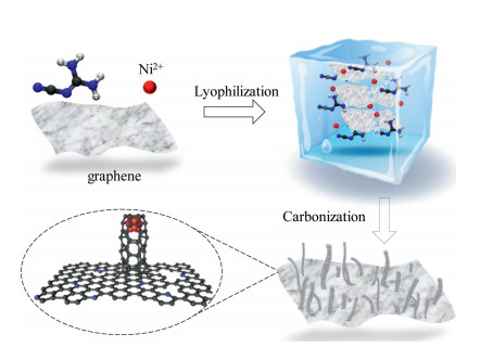
The fabrication process for N/NiNPs@CNT/G was illustrated in Fig. 1. The freeze-dried Ni2+/dicyandiamide functionalized gra-phene composite precursor was prepared through mixing nickel acetylacetonate and dicyandiamide in graphene suspension, followed by thermal carbonization and acid etching treatments to obtain final product of N/NiNPs@CNT/G. In consistence with the typical tip-growth mechanism as reported previously [10, 12], during the thermal carbonization process, the Ni2+ ions was firstly reduced to Ni NPs adhered to the surface of graphene. Then formed Ni NPs induced the growth of CNTs from decomposed dicyandia-mide with direct covalent bonding between CNTs and graphene. Further, the CNTs moved with the growing tip and gradually pushed away from the graphene layers. When the Ni NPs were completely encapsulated by carbon layers, the in situ growth of CNTs stopped, which lead to the successful formation of 3D hybrid structure. Meanwhile, the decomposition of N-containing dicyan-diamide also resulted in the doping of N species into overall 3D hybrid nanocarbon.

|
Download:
|
| Fig. 1. Schematic diagram for the synthesis procedure of N/NiNPs@CNT/G. | |
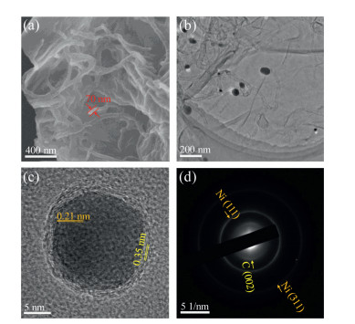
The microstructure morphologies of N/NiNPs@CNT/G, Ni NPs loaded graphene (NiNPs/G), and N-doped graphene (NG) were characterized via scanning electron microscopy (SEM). As dis-played in Fig. 2a, the surface of graphene was well covered by countable CNTs forming a 3D N/NiNPs@CNT/G hybrid structure, which was clearly distinguished with that of the NG and NiNPs/G (Fig. S1 in Supporting information). The diameter of CNTs in the N/NiNPs@CNT/G was approximately determined to be 70 nm, and these CNTs in the hybrid were interleaved with each other in micrometer scale, benefiting for mass transfer and high exposure of active surface area [13]. Further transmission electron micros-copy (TEM) image of N/NiNPs@CNT/G showed that these Ni NPs were encapsulated at the end of CNTs and further tightly assembled on graphene (Fig. 2b), supporting the tip-growth mechanism. Additionally, as clearly displayed in the high-resolution TEM image (Fig. 2c), the Ni NPs was well coated by several layers of graphitic carbon nanosheets, where the inherent lattice spacings of inside Ni NPs and outside carbon layers were about 0.21 nm and 0.35 nm, respectively, in consistence with the Ni (111) and graphite (002) planes. The layer number of CNT's walls was determined to be five, nearly the same with that of NiNPs/G which possessed the same carbon-encircle Ni NPs structure as above mentioned without any N dopant (Fig. S2a in Supporting information). Further, scattered dots and several rings shown in selected area electron diffraction (SAED) pattern were in response to the corresponding diffraction facets of crystalline Ni NPs and graphitic carbon, respectively (Fig. 2d). These morphology results evidently proved the unique 3D hybrid structure where the CNT-encapsulated Ni NPs were assembled on the surface of graphene.

|
Download:
|
| Fig. 2. (a) SEM image, (b) TEM image and (c) HRTEM image of N/NiNPs@CNT/G. (d) SAED pattern of N/NiNPs@CNT/G. | |
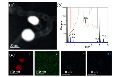
To trace the element compositions of N/NiNPs@CNT/G, scanning transmission electron microscopy (STEM) was conducted in the area of two individual Ni NPs with particle sizes of below 100 nm (Fig. 3a), and corresponding energy-dispersive X-ray spectroscopy (EDX) spectrum revealed the co-existence of C, N, O, and Ni elements. Additionally, the corresponding EDX mapping images (Figs. 3a and c) uncovered the homogeneous distribution of N species on the 3D hybrid and the existence of Ni NPs in carbon matrix, in coincidence with EDX spectrum (Fig. 3b). Thus, the successful doping of N atoms into whole structure of carbon supports was concluded from above results.

|
Download:
|
| Fig. 3. (a) STEM image of two individual Ni NPs in N/NiNPs@CNT/G. (b, c) EDX spectrum and EDX mapping images of the region shown in (a). | |
As shown in X-ray diffraction (XRD) patterns (Fig. 4a), both N/NiNPs@CNT/G and NiNPs/G samples existed two obvious diffraction peaks located at approximately 44.5° and 51.8°, assigning to the (111) and (200) planes of Ni NPs, respectively.

|
Download:
|
| Fig. 4. (a) XRD patterns of N/NiNPs@CNT/G, NiNPs/G and N/G. (b) XPS full spectra, (c) high resolution Ni 2p XPS spectrum and (d) high resolution N 1s XPS spectrum of N/NiNPs@CNT/G. | |
In addtion, one typical broad peak located at about 26° coincided well with the reflection of the (002) plane of graphitic carbon support in N/NiNPs@CNT/G. Owing to the higher content of Ni NPs, the N/ NiNPs@CNT/G owned the sharper Ni peaks but the broader carbon peak than the NiNPs/G, in good agreement with the low graphitization degree of N/NiNPs@CNT/G. To get deep insight into the chemical compositions of N/NiNPs@CNT/G, X-ray photoelectron spectroscopy (XPS) was further applied to characterize the compositions and chemical states of Ni and N species. The XPS full spectrum (Fig. 4b) disclosed the presence of Ni, N, O, and C elements in N/NiNPs@CNT/G, the absence of N element in the NiNPs/G, and the missing of Ni element in the N/G. Based on above XPS results, the loading amount of Ni species in the N/NiNPs@CNT/G was determined to be 1.22 at% (Table S2 in Supporting information). Such a low amount of the Ni species in N/NiNPs@CNT/G pointed at that the residual Ni NPs was encapsulated by CNTs after acid etching treatment. Further, the content of N species in N/NiNPs@CNT/G was estimated to be 7.27 at% that was nearly the same to that of N/G (7.72 at%). In the high resolution XPS Ni 2p spectra of N/NiNPs@CNT/G and NiNPs/G, the dominating peaks emerged at 853.8 eV and 871.6 eV were specifically matched with the Ni 2p3/2 and Ni 2p1/2 of metallic Ni0(Fig. 4c and Fig. S3a in Supporting information), agreed well with the XRD results. In the high resolution XPS N 1s spectra of N/NiNPs@CNT/G and N/G (Fig. 4d and Fig. S3b in Supporting information), four typical types of N species centered at 398.5, 399.9, 401.2, and 403.1 eV were well assigned to pyridinic N, pyrrolic N, graphitic N, and oxidized N, respectively. In contrast to N/G, the ratio of pyridinic N was relatively high among total N species in the N/NiNPs@CNT/G, which may benefit for electrical conductivity on graphene because of the extra lone pair of electrons [14].
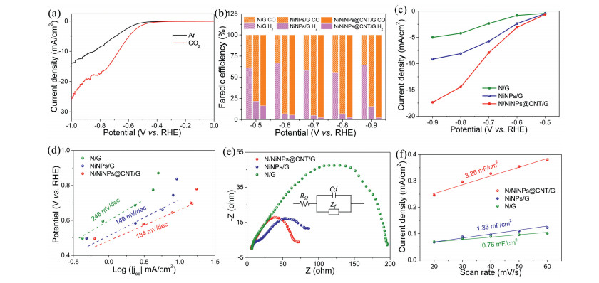
To assess the CRR activity, as-prepared N/NiNPs@CNT/G, controlled NiNPs/G and N/G samples were investigated by a custom three-electrode H-type electrolytic cell with Nafion membrane separated 0.5 mol/L KHCO3 electrolyte (pH 7.2). As shown in Fig. 5a, linear sweep voltammetry (LSV) curve in CO2-saturated electrolyte displayed that the N/NiNPs@CNT/G featured with a current density of 12.2 mA/cm2 at -0.7 V, twice times higher than that in Ar-saturated KHCO3 electrolyte at the same potential, confirming that the CRR process efficiently overcame hydrogen evolution reaction (HER). Further, an onset potential as low as 0.3 V was obtained from the LSV curve of N/NiNPs@CNT/G, which indicated that the N/NiNPs@CNT/G hybrid possessed prominent electrocatalytic activity for CRR. The gas and liquid products of N/NiNPs@CNT/G toward CRR catalysis were detected by gas chromatography (GC) and nuclear magnetic resonance spectroscopy, respectively. The generated CO and H2 products were the only two reduction products monitored from the GC output (Fig. S4 in Supporting information), and no liquid products could be detected.

|
Download:
|
| Fig. 5. (a) LSV curves of N/NiNPs@CNT/G in Ar-saturated or CO2-saturated 0.5 mol/L KHCO3 solutions. (b-f) FEs for CO and H2 products, CO partial current densities, Tafel slopes, Nyquist plots (the insert is analog diagram), calculated electrochemical active area values of N/NiNPs@CNT/G, NiNPs/G and N/G. | |
The results in Fig. 5b displayed that the N/NiNPs@CNT/G possessed the maximum FE of 97.7% for producing CO at a moderately negative potential of -0.7 V. Moreover, the N/NiNPs@CNT/G held the CO selectivity over 94% in a broad potential window between 0.6 V and -0.9 V. In contrast, control NiNPs/G reached an inferior eletrocatalytic property with maximal CO FE of 92.9% at -0.7 V, and CO selectivity over 89% during 0.6~0.9 V. In sharp contrast, the CRR performance of N/G was much lower than those of both N/NiNPs@CNT/G and NiNPs/G, achieving the maximal CO FE of 40.6% at -0.8 V, proving that the super catalytic activity was chiefly ascribed to the introduced CNT-encapsulated Ni NPs. Further, compared with the severe H2 generation on Ni NPs as reported before [15], it can be concluded that the CNT-encapsulated Ni NPs was the precise major cause for boosting CRR rather than pure Ni NPs. Meanwhile, the CO partial current density of 7.9 mA/cm2 at -0.7 V for N/NiNPs@CNT/G was much higher than that of NiNPs/G and N/G (Fig. 5c), implying that the N dopants could efficiently improve the electrical conductivity and thus enhance their overall catalytic activity [16]. In addition, Tafel slopes were employed to quantify the CRR reaction kinetics for CO production by the logarithm of CO partial current density. As displayed in Fig. 5d, the measured Tafel slope for N/NiNPs@CNT/G was 134 mV/dec, lower than that of NiNPs/G (149 mV/dec) and N/G (248 mV/dec), indicating a high kinetic activity of N/NiNPs@CNT/G. Besides, the gained Tafel slopes' values of all controlled samples were higher than 118 mV/dec, demonstrating the one electron transfer process on CRR catalysis, so the rate determining step of all controlled samples was proved to be the CO2 activation step [17]. Further insight into CRR reaction kinetics was gained from the electrochemical impedance spectroscopy (EIS) tested at a potential of -1.2 V. In Fig. 5e, it can be found that the lower charge transfer resistance accounted for smaller impedance arcs of N/NiNPs@CNT/ G relative to the NiNPs/G and NG, directing at high electrical conductibility. Meanwhile, the double-layer capacitance of N/NiNPs@CNT/G was obtained through plotting the capacitive current density associated against the different scan rates via cyclic voltammetry (CV) curves (Fig. S5 in Supporting information). According to the calculated double-layer capacitances, the N/NiNPs@CNT/G behaved the largest electrochemical active surface area among N/NiNPs@CNT/G (3.25 μF/cm2), NG (1.55 μF/cm2), and NiNPs/G (0.76 μF/cm2) samples (Fig. 5f), suggesting that highly exposed active sites were formed on 3D N/NiNPs@CNT/G hybrid. Concluded from these results, the CNT-encapsulated Ni NPs structure owned powerful activation effect on CRR catalysis, and the doped N species on the 3D structure are unambiguously responsible for high current density.
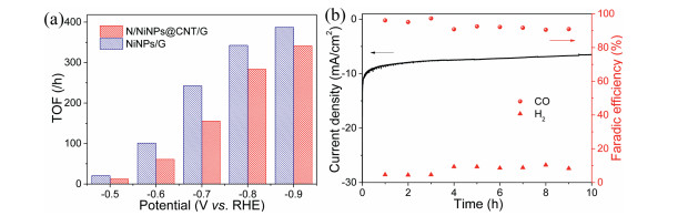
Furthermore, turnover frequency (TOF) of N/NiNPs@CNT/G was determined to assess the intrinsic catalytic rate normalized to each Ni atoms. As shown in Fig. 6a, a much larger TOF value of 387.3 CO/h for CO formation was determined for N/NiNPs@CNT/G at a potential of -0.9 V, than that of NiNPs/G (348.9 CO/h), owing to the favor of N dopants in CRR catalysis. Finally, long term CRR stability of N/NiNPs@CNT/G was carried out at -0.7 V, in which the CO FE of N/NiNPs@CNT/G maintained over 90% and the current density displayed an ignorable decay over a 10 h test period (Fig. 6b). Thus, these experimental results comprehensively demonstrated the efficient and stable catalytic performance of N/NiNPs@CNT/G for CRR.

|
Download:
|
| Fig. 6. (a) TOFs of N/NiNPs@CNT/G and NiNPs/G. (b) Current density and FEs of CO and H2 for N/NiNPs@CNT/G at -0.7 V. | |
In summary, a 3D hybrid CRR electrocatalyst consisting of graphene, countable CNTs, and Ni NPs along with the doping of N species was designed via a pyrolysis treatment of graphene/Ni2+/dicyandiamide functionalized composite. Owing to the CNT-encapsulated Ni NPs and N dopant, the obtained N/NiNPs@CNT/G achieved the high CO FE of close to 97.7% at -0.7 V, and the considerable CO partial current density of 7.9 mA/cm2, which was superior to most previously reported metallic NPs loaded carbon based CRR electrocatalysts till now. Interestingly, comprehensive experimental studies and structural characterizations demon-strated that CNT-encapsulated Ni NPs played crucial effect on elevating the selectivity of CO2 to producing CO via CRR, and the improved current density was originated in the N doping on whole structure. Our findings can provide a thoughtful direction to design low cost and highly efficient carbon based CRR electrocatalysts, which will provide an innovative avenue for wider applications in electrochemistry.
Declaration of competing interestThe authors declare that they have no known competing financial interests or personal relationships that could have appeared to influence the work reported in this paper.
AcknowledgmentsWe thank the support of the National Natural Science of Fundation of China (Nos. 51702284, 21878271, 21878270 and 21961160742), Natural Science Foundation of Zhejiang Province (No. LR19B060002), the Fundamental Research Funds for the Central Universities, and the Startup Foundation for Hundred-Talent Program of Zhejiang University.
Appendix A. Supplementary dataSupplementary material related to this article can be found, in the online version, at doi:https://doi.org/10.1016/j.cclet.2020.04.056.
| [1] |
N. Mac Dowell, P.S. Fennell, N. Shah, G.C. Maitland, Nat. Clim. Change 7 (2017) 243-249. DOI:10.1038/nclimate3231 |
| [2] |
T. Wang, Q. Zhao, Y. Fu, et al., Small Methods 3 (2019) 1900210. DOI:10.1002/smtd.201900210 |
| [3] |
(a) L. Wang, J. Cao, X. Cheng, et al., ACS Sustainable Chem. Eng. 7(2019) 10044-10051; (b) C. Lu, J. Yang, S. Wei, et al., Adv. Funct. Mater. 29(2019) 1806884; (d) W. Shi, J. Mao, X. Xu, et al., J. Mater. Chem. A 7(2019) 15654-15661; (e) W. Liu, L. Yu, R. Yin, et al., Small 16(2020) 1906775; (f) X. Xu, W. Shi, P. Li, et al., Chem. Mater. 29(2017) 6058-6065. |
| [4] |
W. Zheng, J. Yang, H. Chen, et al., Adv. Funct. Mater. 30 (2019) 1907658. |
| [5] |
G.L. Tian, M.Q. Zhao, D. Yu, et al., Small 10 (2014) 2251-2259. DOI:10.1002/smll.201303715 |
| [6] |
Z. Fan, J. Yan, L. Zhi, et al., Adv. Mater. 22 (2010) 3723-3728. DOI:10.1002/adma.201001029 |
| [7] |
D.H. Lee, J.E. Kim, T.H. Han, et al., Adv. Mater. 22 (2010) 1247-1252. DOI:10.1002/adma.200903063 |
| [8] |
E. Yoo, J. Kim, E. Hosono, et al., Nano Lett. 8 (2008) 2277-2282. DOI:10.1021/nl800957b |
| [9] |
D. Yu, L. Dai, J. Phys. Chem. Lett. 1 (2010) 467-470. DOI:10.1021/jz9003137 |
| [10] |
Y. Hou, S. Cui, Z. Wen, et al., Small 11 (2015) 5940-5948. DOI:10.1002/smll.201502297 |
| [11] |
W. Zheng, C. Guo, J. Yang, et al., Carbon 150 (2019) 52-59. DOI:10.1016/j.carbon.2019.04.112 |
| [12] |
V. Sridhar, H.J. Kim, J.H. Jung, et al., ACS Nano 6 (2012) 10562-10570. DOI:10.1021/nn3046133 |
| [13] |
J. Liang, R.F. Zhou, X.M. Chen, Y.H. Tang, S.Z. Qiao, Adv. Mater. 26 (2014) 6074-6079. DOI:10.1002/adma.201401848 |
| [14] |
Y. Zhao, J. Liang, C. Wang, J. Ma, G.G. Wallace, Adv. Energy Mater. 8 (2018) 1702524. DOI:10.1002/aenm.201702524 |
| [15] |
K. Jiang, S. Siahrostami, T. Zheng, et al., Energy Environ. Sci. 11 (2018) 893-903. DOI:10.1039/C7EE03245E |
| [16] |
(a) Q. Li, W. Zhu, J. Fu, et al., Nano Energy 24(2016) 1-9; (b) C. Wang, Y. Wang, H. Yang, et al., Small 14(2018) 1802895; (c) J. Cao, C. Lei, J. Yang, et al., J. Mater. Chem. A 6(2018) 18877-18883. |
| [17] |
Y. Liu, S. Chen, X. Quan, H. Yu, J. Am. Chem. Soc. 137 (2015) 11631-11636. DOI:10.1021/jacs.5b02975 |