 2020, Vol. 31


b State Key Laboratory of Hollow-fiber Membrane Materials and Membrane Processes, School of Environmental and Chemical Engineering, Tianjin Polytechnic University, Tianjin 300387, China
The exhaustion of fossil fuels and serious environmental pollution caused by using fossil fuels have immensely increased the demand for renewable and clean energy sources, which intensively drives developments in energy storage devices [1, 2]. As the dominant energy storage device, lithium-ion batteries (LIBs) have dominated the market for portable electronics, electric vehicles and grid-scale electricity storage systems because of their high energy densities, long cycle life, and environmental benignity, and the demand grows rapidly in recent years [3]. However, there are serious concerns about the cost increase and the sustainability of LIBs due to the limited lithium resources and the increasing demand [4]. Therefore, it is extremely necessary to develop alternative energy storage devices with low cost, high safety, good performances, and natural abundance of raw materials. Recently, sodium-ion batteries (SIBs) are considered as one of the most promising energy storage devices for large-scale electricity storage systems owing to their low cost, the natural abundance of sodium resource, and basically similar components and working mechanisms to LIBs [5]. Nevertheless, some inevitable issues are restricting their large-scale applications. Compared to lithium, sodium has a larger ionic radius (1.02 Å for Na+ vs. 0.76 Å for Li+) and heavier atomic weight (22.99 g/mol for Na vs. 6.94 g/mol for Li). Moreover, the standard electrochemical potential of sodium (2.71 V) is lower than lithium (3.04 V) [4]. These differences cause a sluggish reaction kinetics and critical conditions for Na+ diffusion, which make the performances of SIBs undesirable [6]. Generally, electrode materials play important roles in determining the electrochemical performance. Therefore, it is critical to develop suitable electrode materials with optimal electrochemical performances.
Many advanced cathode materials for SIBs have been reported [7, 8]. However, the search for suitable anode materials with high specific capacity, long-termcyclinglife, andhigh structure stabilityis still a major challenge [4, 8]. Among the materials as anode for SIBs, transition metal sulfides, one of the conversion reaction-based materials, are potential and competitive with other anode materials because of their high theoretical capacity, low cost, and improved mechanical stability and electrical conductivity compared to their metal oxide counterparts [8, 9]. Typically, MnS has received tremendous attention due to high theoretical capacities of 616 mAh/g, environmental friendliness, and earth abundance [10-12]. However, MnS suffers from low ionic/electrical conductivity, large volume change, and electrode pulverization, resultinginfast capacity fading and poor cycling stability [13-15].Themost common strategies to mitigate these issues are designing nanostructure and carbon hybridization [6, 8]. One of the most widely designed nanostructures is hollow structure, which can enlarge contact area between the active materials and electrolyte, provide more electroactive sites, reduce the diffusion length for ions and electrons, and alleviate the large volume expansion [5, 16-19]. However, the electrochemical performanceof the pure MnS electrodewith hollow structure is still unsatisfied due to their intrinsically low conductivity, collapse of the structures, and agglomeration of the nanoparticles [8, 10]. As previously reported, designing hybrids with carbonaceous materials such as amorphous carbon [20-22], reduced graphene oxide [23-25], carbon fibers [26, 27], carbon nanotubes [28, 29], and carbon cloth [30], has been proved to be an effective strategy to enhance the electrochemical performance of the metal sulfides. For instance, Gao et al.obtained carbon-coatedMnS hybrid byannealing Mn-based metal-organic frameworks with sulfur [21]. The porous amorphous carbon increases the electrical conductivity, facilitates the transport of ions and electrons, and effectively buffers the volume change. Therefore, the MnS/C electrode shows a reversible capacity of 297 mAh/g at 50 mA/g after 100 cycles. Carbon nanotubes (CNTs) are also promising carbonaceous materials for improving the electrochemical performance of electrodes owing to their excellent electrical conductivity and good mechanical/ chemical stability [31, 32]. For example, our group prepared FeS2/ CNTcomposite bya simple solvothermal method, which exhibited a satisfied capacity of 394 mAh/g at 200 mA/g after 400 cycles [28]. Therefore, developing CNTs modified MnS with the hollow structure is promising for achieving anode with excellent electrochemical performance.
Herein, we designed and synthesized hollow MnS/CNTs composite by a facile one-step solvothermal method. The schematic illustration of the synthesis process of the hollow MnS/CNTs composite is shown in Fig. S1 (Supporting information). Firstly, moderate amount of CNTs (TNSM1, Chengdu, China; weight ratio of MnS to CNTs of 2:1) were homogeneously dispersed into 60 mL of dimethylformamide (DMF) by ultrasonication for 1 h. Then, Mn(CH3COO)2·4H2O (0.6528 g) was added to the CNTs suspension and magnetically stirred for 30 min at room temperature. Meanwhile, an aqueous solution (10 mL) of dissolved L-cysteine (0.6488 g) was made by ultrasonication for 30 min. After that, the L-cysteine solution was added to the mixture of CNTs and Mn(CH3COO)2·4H2O dropwise and stirred for 30 min at room temperature. Finally, the above solution was transferred into a 100 mL Teflon-lined sealed autoclaves and maintained at 200 ℃ for 12 h. After the reaction, the precipitates were cooled to room temperature naturally, and then centrifuged and washed with deionized water and ethanol several times. The final products were obtained by drying at 60 ℃ for 12 h under vacuum. For comparison, MnS/CNTs composites with different weight ratios of MnS to CNTs (6:1 and 4:3) were also synthesized by the same method to determine the optimal ratio and obtain the best electrochemical performance. Pure MnS was prepared using the similar route without the addition of CNTs. The characterization and electrochemical measurements process can be seen in the Supporting information.
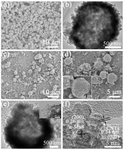
The morphology and microstructure of the pure MnS and the hollow MnS/CNTs composite were observed by scanning electron microscopy (SEM) and transmission electron microscopy (TEM). The SEM image of the pure CNTs is shown in Fig. S2 (Supporting information). Fig. 1a and Fig. S3 (Supporting information) show the SEM images of the pure MnS, in which the uniform microspheres are composed of MnS nanoparticles. The TEM image (Fig. 1b) displays the pale center region in contrast against the dark edge, suggesting the hollow structure of the pure MnS microspheres. As shown in the SEM images of the hollow MnS/CNTs composite Figs. 1c and d), the MnS microspheres homogeneously disperse in the 3D interlaced CNTs network, meanwhile, the CNTs make the independent MnS microspheres interconnect with each other. The inset of Fig. 1d displays that some CNTs thread into the MnS microspheres and combine with MnS nanoparticles which compose the MnS microspheres. Meanwhile, X-ray photoelectron spectroscopy (XPS) spectrum (Fig. S4 in Supporting information) shows the existence of C-S-Mn bond, indicating that the CNTs combine chemically with the MnS nanoparticles, which is in favor of improving the electron transfer [33]. Therefore, the CNTs form an integrative and uniform conductive network, which can facilitate the transport of electrons and ions [32]. Nevertheless, the non-uniform dispersion of CNTs in the MnS/CNTs (6:1) composite (Figs. S5a and b in Supporting information) cannot construct integrative conductive network owing to the littlie content of CNTs, only improving the partial electrical conductivity. High content of CNTs in the MnS/CNTs (4:3) composite (Figs. S5c and d in Supporting information) results in serious agglomeration of CNTs and decrease the amount of MnS active material. The typical TEM images of the hollow MnS/CNTs composite (Fig. 1e and the inset) also show the combinations among the CNTs, MnS nanoparticles, and the MnS microspheres. The hollow structure of the MnS microspheres in the hollow MnS/CNTs composite can be verified by the TEM image. The hollow structure can effectively shorten the diffusion distance of Na+, improve the contact area between the electrodes and electrolyte, offer more active sites, and accommodate the volume change [19]. The HRTEM image (Fig. 1f) shows the lattice spacing of about 0.26 nm and 0.34 nm for the (200) plane of α-MnS and (002) plane of CNTs, respectively [20].

|
Download:
|
| Fig. 1. (a) SEM image and (b) TEM image of pure MnS; (c, d and the inset) SEM images, (e and the inset) TEM images and (f) HRTEM image of hollow MnS/CNTs composite. | |
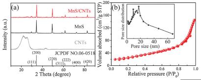
The XRD patterns of pure MnS, CNTs, and the hollow MnS/CNTs composite are shown in Fig. 2a. All diffraction peaks of the hollow MnS/CNTs composite can be indexed to α-MnS (JCPDF No. 06- 0518), and no impurity phase is detected [20, 34]. The extremely weak diffraction peak around 26° of the hollow MnS/CNTs composite corresponds to the CNTs [28, 31]. The Raman spectra (Fig. S6 in Supporting information) further confirms the presence of MnS and CNTs in the hollow MnS/CNTs composite [29]. The carbon content in the hollow MnS/CNTs composite was measured by Thermogravimetric Analysis (TGA), as shown in Fig. S7 (Supporting information), the calculated result shows that the weight ratio of CNTs in the hollow MnS/CNTs composite is 31.9%. N2 adsorption/desorption measurements were taken to characterize the specific surface area and pore size distribution of the hollow MnS/CNTs composite. As shown in Fig. 2b, the isotherms are identified as type-Ⅳ isotherms, which are characteristic of mesoporous materials [15, 28]. The N2 adsorption/desorption isotherms and the pore-size distribution of pure MnS and CNTs are shown in Figs. S8a and b (Supporting information). The BET specific surface area of the hollow MnS/CNTs composite is calculated to be 93.6 m2/g, pore volume was 0.20 cm3/g, much larger than those of pure MnS (18.8 m2/g, 0.03 cm3/g). The pore size distribution calculated by the Barrett Joyner Halenda (BJH) method shows that the hollow MnS/CNTs composite is porous composite with a narrow distribution between 9–17 nm. The abundant mesoporous, large surface area, and high pore volume are benefit for increasing the electrode/electrolyte contact area, providing ionic transport pathways and accommodating the stress relaxation during charge/discharge process [20, 28].

|
Download:
|
| Fig. 2. (a) XRD patterns of pure MnS, CNTs, and hollow MnS/CNTs composite; (b) N2 adsorption-desorption isotherm and pore size distribution of hollow MnS/CNTs composite. | |
The electrochemical performances of the hollow MnS/CNTs electrode for SIBs were systematically tested, as shown in Fig. 3. The cyclic voltammetry (CV) curves of the hollow MnS/CNTs electrode in the potential range of 0.01–3 V (vs. Na/Na+) at 0.1 mV/s are shown in Fig. 3a. In the first cathodic scan, a broad reduction peak between 1.4 V and 0.7 V is attributed to the irreversible formation of solid electrolyte interface (SEI) [24]. The peak at 0.2 V is related to the electrochemical reduction of MnS and generation metallic Mn and Na2S [21, 24]. For the first anodic scan, two peaks at about 2 V and 2.2 V can be indexed to the two-step reverse reactions from metallic Mn to MnS [10] In the subsequent scans, the new reduction peak appeared at about 1.5 V corresponds to the insertion of Na+ into the MnS and the peak at 0.2 V moves notably to about 0.3 V which is ascribed to the reduction of MnS [10], meanwhile, the oxidation peak at 2 V shifts to about 1.8 V. Such situation is attributed to the formation of SEI and the structural change of active material caused by an irreversible phase transition due to the formation of Na2S and S during Na+ insertion/extraction process [15, 27, 35]. Fig. 3b shows the galvanostatic charge/ discharge curves of the hollow MnS/CNTs electrode at a constant current density of 100 mA/g. In the first cycle, the hollow MnS/ CNTs electrode delivers a discharge capacity of 649 mAh/g and charge capacity of 401 mAh/g with an initial coulombic efficiency (ICE) of 61.8%. The irreversible capacity loss mainly arises from the irreversible formation of SEI and electrolyte decomposition [24].

|
Download:
|
| Fig. 3. (a) Cyclic voltammetry curves and (b) galvanostatic charge/discharge curves of hollow MnS/CNTs electrode. Cycling performance and coulombic efficiency of hollow MnS/CNTs electrode and pure MnS electrode at 100 mA/g (c) and 500 mA/g (d). (e) Rate performance of hollow MnS/CNTs electrode and pure MnS electrode. (f) Electrochemical impedance spectroscopy of hollow MnS/CNTs electrode and pure MnS electrode. | |
The sodium storage ability of the hollow MnS/CNTs electrode and pure MnS electrode at a current density of 100 mA/g is shown in Fig. 3c. Meanwhile, the sodium storage performance of the pure CNTs is also provided in Fig. S9 (Supporting information). The initial discharge capacity of the hollow MnS/CNTs electrode is as high as 649 mAh/g, with an ICE of 61.8%. Meanwhile, the pure MnS electrode delivers an initial discharge capacity of 534 mAh/g, with an ICE of 66.4%. The low ICE is mainly due to the formation of SEI and electrolyte decomposition [22]. It is worth noting that the hollow MnS/CNTs electrode has a lower ICE than the pure MnS electrode, which is mainly due to the larger specific surface area of the hollow MnS/CNTs composite than that of the pure MnS, resulting in the generation of more SEI and lower ICE for the hollow MnS/CNTs electrode [27, 36]. After 100 cycles, the hollow MnS/ CNTs electrode remains a reversible capacity of 275 mAh/g, with a coulombic efficiency of 99.5%, whereas the reversible capacity of pure MnS electrode is only 25 mAh/g. When cycled at a higher current density of 500 mA/g (Fig. 3d), the hollow MnS/CNTs electrode still delivers a reversible capacity of 136 mAh/g, which is 5 times higher than that of pure MnS electrode (27 mAh/g). The pure CNTs electrode delivers much lower capacity (Fig. S9). For the MnS/CNTs (6:1) electrode, which the content of the CNTs is not enough to construct integrative conductive network, the sodium storage performance is not effectively improved compared with the pure MnS electrode. For the MnS/CNTs (4:3) electrode, although the conductive network is formed, the excessive content of the CNTs which have inferior electrochemical performance is negative to improve the reversible capacity of the MnS/CNTs (4:3) electrode (Fig. S10 in Supporting information) [28]. Obviously, the cycle performance of the hollow MnS/CNTs electrode is much better than that of pure MnS electrode, the MnS/CNTs (6:1) electrode and MnS/CNTs (4:3) electrode. The enhanced electrochemical performance of the hollow MnS/CNTs electrode can be ascribed to the synergistic effects between the MnS hollow microspheres and the 3D CNTs network. The rational combination of the MnS hollow microspheres with CNTs can build an integrative and uniform 3D network structure, which can effectively enhance electrical conductivity and accommodate the volume expansion [32]. This is benefit for not only facilitating the transport of electrons and ions but also improving the sufficient electrode/ electrolyte contact area [37]. The direct mixing of pure MnS and the CNTs (m-MnS/CNTs) with a weight ratio of 2:1 was also carried out and tested sodium storage performance (Fig. S11 in Supporting information). The inferior electrochemical performance of the m-MnS/CNTs suggests that simply mixing pure MnS with the CNTs is not positive for the satisfied specific capacity, which further indicates that not only the integrative and uniform 3D CNTs network structure but also the synergistic interaction between the MnS hollow microspheres and the 3D CNTs network plays an important role in enhancing the electrochemical performance of the hollow MnS/CNTs electrode [27, 28].
Fig. 3e shows the rate capability of the hollow MnS/CNTs electrode and pure MnS electrode at current densities from 50 mA/g to 1000 mA/g. The reversible capacity of the hollow MnS/ CNTs electrode is up to 385 mAh/g at 50 mA/g. It can be observed that the hollow MnS/CNTs electrode exhibits the reversible capacities of 321, 277, 225, 190 and 170 mAh/g at various current densities of 100, 200, 500, 800 and 1000 mA/g, respectively, which are much better than those of pure MnS electrode. When the current density decrease back to 100 mA/g, the hollow MnS/CNTs electrode can recover to a reversible capacity of 260 mAh/g, and maintain a stable discharge specific capacity of 247 mAh/g after subsequent 70 cycles, whereas the reversible capacity of pure MnS electrode is only 55 mAh/g after subsequent 70 cycles. Compared with the hollow MnS/CNTs electrode, the rate capability of the MnS/CNTs (6:1) electrode and the MnS/CNTs (4:3) electrode is unsatisfied (Fig. S12 in Supporting information). We also compared the electrochemical performance of the hollow MnS/CNTs electrode with the state-of-the-art MnS-based materials in previous reports (Table S1 in Supporting information). Compared to most of the previous works, the hollow MnS/CNTs electrode is well matched in rate capability and cycle stability.
In order to better understand the enhanced electrochemical performance of the hollow MnS/CNTs electrode, electrochemical impedance spectroscopy (EIS) measurements of the hollow MnS/ CNTs electrode and pure MnS electrode are shown in Fig. 3f. The equivalent circuit is shown in Fig. S13 (Supporting information). The curves include a semicircle in the high-frequency region and a straight line in the low-frequency region, corresponding to the resistance of the electrode and sodium ion diffusion, respectively [24]. The hollow MnS/CNTs electrode has a smaller semicircle than that of the pure MnS electrode, indicating that the charge transfer resistance (Rct) for the hollow MnS/CNTs electrode (217 Ω) is much lower than that for the pure MnS electrode (798 Ω). The result indicates that the introduced CNTs can enhance the electronic conductivity and enable much easier charge transfer [32, 37]. The linear part of the hollow MnS/CNTs electrode is steeper than that of pure MnS electrode, which indicates faster ion diffusion [31]. The above analysis suggests that combining with CNTs can effectively improve the electrical conductivity of the composite and facilitate the transport of ions, which can enhance the electrochemical performance as observed above [37].
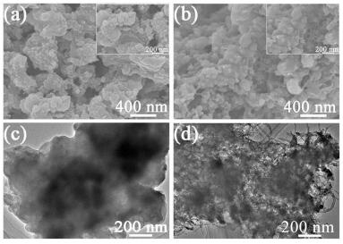
The hollow MnS/CNTs electrode and the pure MnS electrode after 100 cycles cycling test at 100 mA/g were investigated to study the structuralvariation. As shown in Fig. 4a, there aremany cracks on the surface of the pure MnS electrode, which is attributed to the large volume strain in the process of insertion/extraction of Na+. These cracks cause the loss of electric contact between active materials, conductive carbon and current collector, which go against the transportation of electrons and ions [37]. In contrast, the hollow MnS/CNTs electrode (Fig. 4b) has little cracks, suggesting that the hollow MnS/CNTs electrode can sustain over the volume change. The different shade on the pure MnS electrode (Fig. 4c) is related to the serious particles aggregation. Benefiting from the synergistic interaction with CNTs, the MnS nanoparticles on the hollow MnS/ CNTs electrode (Fig. 4d) combine uniformly with the CNTs, which is good for facilitating the transport of electrons and ions.

|
Download:
|
| Fig. 4. (a and inset) SEM images and (c) TEM image of pure MnS electrode after 100 charge/discharge cycles; (b and inset) SEM images and (d) TEM image of hollow MnS/CNTs electrode after 100 charge/discharge cycles. | |
In summary, the hollow MnS/CNTs composite with MnS hollow microspheres disperse in the interlaced CNTs was prepared by a onestep solvothermal method. The CNTs intertwine with the MnS hollow microspheres and partly thread into them. Such architecture and combination have the advantages of improving electrical conductivity, accelerating ionic diffusion, facilitating electrode/electrolyte contact, and accommodating the volumetric expansion. As a result, the hollow MnS/CNTs composite used as anode in SIBs exhibits enhanced sodium storage in terms of higher reversible capacity (275 mAh/g at 100 mA/g after 100 cycles) than that of pure MnS (25 mAh/g at 100 mA/g after 100 cycles). It can still deliver a five times higher reversible capacity than that of the pure MnS electrode at a higher current density of 500 mA/g. The hollow MnS/CNTs electrode also exhibits superior rate performance (385, 321, 277, 225, 190 and 170 mAh/g at 50, 100, 200, 500, 800 and 1000 mA/g, respectively), and the capacities of pureMnS electrode at 800 and 1000 mA/g are less than 10 mAh/g. Therefore, the hollow MnS/CNTs composite synthesized by solvothermal method is considered to be a potential candidate anode material in SIBs.
Declaration of competing interestThe authors declare that they have no known competing financial interests or personal relationships that could have appeared to influence the work reported in this paper.
AcknowledgmentsThis work was supported by the National Natural Science Foundation of China (NSFC, Nos. 51772205, 51572192, 51772208, 51472179), and the General Program of Municipal Natural Science Foundation of Tianjin (Nos. 17JCYBJC17000, 17JCYBJC22700).
Appendix A. Supplementary dataSupplementary material related to this article can befound, in the online version, at doi:https://doi.org/10.1016/j.cclet.2019.09.050.
| [1] |
J.Y. Hwang, S.T. Myung, Y.K. Sun, Chem. Soc. Rev. 46 (2017) 3529-3614. DOI:10.1039/C6CS00776G |
| [2] |
X. Zhang, X. Rui, D. Chen, et al., Nanoscale 11 (2019) 2556-2576. DOI:10.1039/C8NR09391A |
| [3] |
X. Pu, H. Wang, D. Zhao, et al., Small (2019) 1805427. |
| [4] |
G.L. Xu, R. Amine, A. Abouimrane, et al., Adv. Energy Mater 8 (2018) 1702403. DOI:10.1002/aenm.201702403 |
| [5] |
F. Xie, L. Zhang, C. Ye, et al., Adv. Mater (2018) 1800492. |
| [6] |
Z. Hu, Q. Liu, S.L. Chou, et al., Adv. Mater 29 (2017) 1700606. DOI:10.1002/adma.201700606 |
| [7] |
M. Tang, H. Li, E. Wang, et al., Chin. Chem. Lett. 29 (2018) 232-244. DOI:10.1016/j.cclet.2017.09.005 |
| [8] |
X. Wei, X. Wang, X. Tan, et al., Adv. Funct. Mater. 28 (2018) 1804458. DOI:10.1002/adfm.201804458 |
| [9] |
H. Yuan, L. Kong, T. Li, et al., Chin. Chem. Lett. 28 (2017) 2180-2194. DOI:10.1016/j.cclet.2017.11.038 |
| [10] |
Y. Liu, L. Li, J. Zhu, et al., ACS Appl. Mater. Interfaces 10 (2018) 27911-27919. DOI:10.1021/acsami.8b05688 |
| [11] |
Y. Hao, C. Chen, X. Yang, et al., J. Power Sources 338 (2017) 9-16. DOI:10.1016/j.jpowsour.2016.11.032 |
| [12] |
G. Li, B. He, M. Zhou, et al., ChemElectroChem 4 (2017) 81-89. DOI:10.1002/celc.201600327 |
| [13] |
D. Xu, R. Jiao, Y. Sun, et al., Nanoscale Res. Lett 11 (2016) 444. DOI:10.1186/s11671-016-1664-6 |
| [14] |
B. Liu, Z. Liu, D. Li, et al., Appl. Surf. Sci. 416 (2017) 858-867. DOI:10.1016/j.apsusc.2017.04.230 |
| [15] |
R. Wang, B. Li, L. Lai, et al., Chem. Eng. J. 355 (2019) 752-759. DOI:10.1016/j.cej.2018.08.136 |
| [16] |
L. Zhang, L. Zhou, H.B. Wu, et al., Angew. Chem. Int. Ed. 51 (2012) 7267-7270. DOI:10.1002/anie.201202877 |
| [17] |
D. Chen, H. Quan, G.S. Wang, et al., ChemPlusChem 78 (2013) 843-851. DOI:10.1002/cplu.201300141 |
| [18] |
S.M. Lee, J.K. Lee, Y.C. Kang, Chem. -Asian J. 9 (2014) 590-595. DOI:10.1002/asia.201301261 |
| [19] |
X. Xu, S. Ji, M. Gu, et al., ACS Appl. Mater. Interfaces 7 (2015) 20957-20964. DOI:10.1021/acsami.5b06590 |
| [20] |
D.H. Liu, W.H. Li, Y.P. Zheng, et al., Adv. Mater. 30 (2018) 1706317. DOI:10.1002/adma.201706317 |
| [21] |
X. Gao, X. Zhang, J. Jiang, et al., Mater. Lett. 228 (2018) 42-45. DOI:10.1016/j.matlet.2018.05.077 |
| [22] |
B.H. Hou, Y.Y. Wang, D.S. Liu, et al., Adv. Funct. Mater. 28 (2018) 1805444. DOI:10.1002/adfm.201805444 |
| [23] |
X. Gao, B. Wang, Y. Zhang, et al., Energy Storage Mater. 16 (2019) 46-55. DOI:10.1016/j.ensm.2018.04.027 |
| [24] |
X. Li, X. Sun, Z. Gao, et al., ChemSusChem 11 (2018) 1549-1557. DOI:10.1002/cssc.201800073 |
| [25] |
W. Chen, X. Zhang, L. Mi, et al., Adv. Mater. 31 (2019) 1806664. DOI:10.1002/adma.201806664 |
| [26] |
S. Gao, G. Chen, Y. Dall'Agnese, et al., Chem. -Eur. J. 24 (2018) 13535-13539. DOI:10.1002/chem.201801979 |
| [27] |
H.H. Fan, H.H. Li, K.C. Huang, et al., ACS Appl. Mater. Interfaces 9 (2017) 10708-10716. DOI:10.1021/acsami.7b00578 |
| [28] |
Y. Chen, X. Hu, B. Evanko, et al., Nano Energy 46 (2018) 117-127. DOI:10.1016/j.nanoen.2018.01.039 |
| [29] |
Z. Shadike, M.H. Cao, F. Ding, et al., Chem. Commun. (Camb.) 51 (2015) 10486-10489. DOI:10.1039/C5CC02564H |
| [30] |
L. Wang, J. Yuan, Q. Zhao, et al., Electrochim. Acta 308 (2019) 174-184. DOI:10.1016/j.electacta.2019.04.019 |
| [31] |
Y. Chen, B. Wang, T. Hou, et al., Chin. Chem. Lett. 29 (2018) 187-190. DOI:10.1016/j.cclet.2017.06.019 |
| [32] |
S.H. Yang, S.K. Park, Y.C. Kang, Chem. Eng. J. 370 (2019) 1008-1018. DOI:10.1016/j.cej.2019.03.263 |
| [33] |
D. Ma, Y. Li, H. Mi, et al., Angew. Chem. Int. Ed. 57 (2018) 8901-8905. DOI:10.1002/anie.201802672 |
| [34] |
D. Wang, D. Cai, B. Qu, et al., CrystEngComm 18 (2016) 6200-6204. DOI:10.1039/C6CE01045H |
| [35] |
R. Tan, J. Yang, J. Hu, et al., Chem. Commun. (Camb.) 52 (2016) 986-989. DOI:10.1039/C5CC08002A |
| [36] |
B.H. Hou, Y.Y. Wang, Q.L. Ning, et al., Adv. Mater. (2019) 1903125. |
| [37] |
G. Huang, F. Zhang, X. Du, et al., ACS Nano 9 (2015) 1592-1599. DOI:10.1021/nn506252u |