 2020, Vol. 31


b School of Chemical Engineering, Dalian University of Technology, Dalian 116024, China
Supercapacitors possessing high power density and long cycle life are the most promising energy storage devices, which have commercial applications such as hybrid vehicles and emergency backup powers [1-5]. Metal hexacyanoferrates (MCHFs, M = Mn, Co, Ni, Cu, etc.) are attractive alternatives to traditional super-capacitor electrode materials because of their unique structure, high capacity and excellent cyclic stability [6-12]. Its 3D open-framework channels which allow fast transport of alkali ions enable high pseudocapacitive performance. In order to achieve high electrochemical performance, the MCHF-based composites which are fabricated with porous carbon, carbon nanotube, graphene and conducting polymers have been tentatively studied [13-26]. Among the MHCFs, CuHCF possesses higher working voltage than NiHCF, CoHCF and MnHCF in neutral aqueous electrolytes [27], suggesting that CuHCF can act as a promising positive electrode material for asymmetrical supercapacitors. Senthilkumar et al. [28] reported the synthesis of CuHCF coated carbon fibers for a high voltage hybrid supercapacitor. Kim et al. [29] used CuHCF and graphitic carbon nanoparticles as positive and negative electrodes, respectively, to assemble an aqueous Li-ion hybrid capacitor with a high capacitance (63.64 F/g) and energy density (42.78 Wh/kg). Yao and coworkers [30] prepared CuHCF nanosheet arrays on carbon cloth, which delivered a capacitance of 1441.4 m F/cm2. Wu et al. [31] synthesized CuHCF nanostructures on the graphene coated stainless steel sheets with a specific capacitance of 570 F/g (1 A/g). Li et al. [32] fabricated a carbon nanotubes/poly(3, 4-ethylenedioxythiophene)-poly(styrenesulfo-nate)/CuHCF hybrid film, which was employed as the positive electrode to build an asymmetrical supercapacitor with an energy density of 30.08 Wh/L (4.25 kW/L).
To date, widely accepted theory concerning the electrochemical energy storage mechanism of MHCFs is that these materials undergo the redox reaction of Fe3+/Fe2+ couple to store charge [6, 7]. And the low spin metal ions (Co2+, Ni2+, Mn2+, etc.) are electrochemically inactive in aqueous electrolytes because of the limited operation potential window. The charge storage of CuHCF is also supposed to be due to the same redox process [31, 32]. Very recently, it has been reported for the CuHCF/reduced graphene oxide nanocomposites that the redox reaction of Cu2+/Cu+ couple may be involved in electrochemical charge storage [33]. But the corresponding redox peaks are not observed in the CV curves of pure CuHCF sample. In the previous studies of CuHCF-related materials for supercapacitors [28-33], considerable efforts have been made to synthesize nanostructured CuHCF or fabricate nanocomposites. However, the information about electrochemical energy storage mechanism is still lacking.
In the present work, the CuHCF nanocubes were synthesized via the chemical co-precipitation method by reacting Cu2+ cations with [Fe(CN)6]3- anions in the presence of potassium citrate. For comparison, the CuHCF particles (CuHCF-P) were prepared by the same method without potassium citrate. Electrochemical proper-ties of the CuHCF-P and -NC materials are studied by CV, galvanostatic charge/discharge tests and electrochemical imped-ance spectroscopy (EIS). A charge storage mechanism is proposed for the CuHCF nanocubes that both Fe3+/Fe2+ and Cu2+/Cu+ redox couples contribute to pseudocapacitance. And it is revealed that the coordination of citrate ions with surface Cu cations plays an important role on activating the Cu2+/Cu+ redox couple.
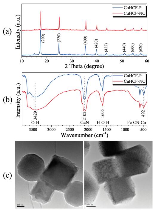
Fig. 1a shows that the CuHCF-P and -NC materials exhibit a face-centered cubic structure, which consists well with that of Prussian blue [27]. As can be seen in the spectra, no diffraction peaks of other phases and impurities are detected, suggesting that both materials have good crystallinity and high purity. The FT-IR spectra of both materials are shown in Fig. 1b. The absorption bands at 2102 and 492 cm-1 are assigned to the —C≡N— stretching mode and Cu-CN-Fe bending mode, respectively [34]. Furthermore, the presence of water molecules inside the CuHCF framework is verified by the absorption bands at 3429 (O—H stretching mode) and 1605 (H—O—H bending mode) cm-1 [35]. Morphologies and particle sizes of the CuHCF-P and -NC materials are characterized by SEM and TEM. As shown in Fig. S1 (Supporting information), a nanocube morphology is observed for the CuHCF-NC sample while an irregular particle morphology for CuHCF-P. Furthermore, it is demonstrated that the Cu, Fe, C and N elements are uniformly distributed in the CuHCF nanocubes according to energy dispersive spectroscopy (EDS) element mapping. TEM images of CuHCF-P (Fig. S2 in Supporting information) and CuHCF-NC (Fig. 1c) are in good accordance with the above SEM results.

|
Download:
|
| Fig. 1. (a) XRD patterns of CuHCFs. (b) FT-IR spectra of CuHCFs. (c) TEM images of CuHCF-NC. | |
The CV curves of the CuHCF-P and -NC electrodes are shown in Fig. 2a. Both electrodes exhibit strong redox peaks, indicating the pseudocapacitive behaviors. The CuHCF-P displays a pair of redox peaks, which are in agreement with theliteratures [31, 32]. A significant difference is found between CuHCF-NC and -P, the CV curve of CuHCF-NC consists of two pairs of well-defined redox peaks. And wide working potential windows of the CuHCF-NC electrode are exhibited (Fig. S3 in Supporting information). Fig. 2b shows the CV curves of CuHCF-NC recorded at different scan rates. Significant potential shifts of redox peaks are observed with increasing scan rates, indicating that the CuHCF-NC electrode undergoes insufficient redox reaction at higher scan rates. Detailed analyses of the galvanostatic charge/discharge profiles of the CuHCF-P (Fig. S4 in Supporting information) and CuHCF-NC (Figs. 2c and d) electrodes show that the Coulombic efficiency (discharge/charge) is more than 91%. In addition, the symmetrical charge and discharge curves imply good electrochemical revers-ibility. The calculated discharge capacitances at different current densities are shown in Fig. 2e. The CuHCF nanocubes exhibit higher specific capacitance than the CuHCF particles. Its specific capaci-tance reaches 296 F/g at 0.5 A/g and retains 263 F/g at 5 A/g. EIS of the CuHCF-P and -NC electrodes are measured and their Nyquist plots are shown in Fig. 2f. In high-frequency region, the depressed semicircles are interpreted to be due to a charge-transfer resistance (Rct) and constant phase element (ZCPE). The straight lines in low-frequency region correspond to the Warburg resistance (ZW). According to the equivalent circuit model shown in the figure, the values of Rct are calculated with the use of ZSimpWin software. They are 4.3 and 2.6 Ω for the CuHCF-P and -NC electrodes, respectively. The charge-transfer resistance of the CuHCF-NC electrode is significantly smaller than that of CuHCF-P.

|
Download:
|
| Fig. 2. (a) CV curves of the CuHCF-P and -NC electrodes. (b) CV curves of the CuHCF-NC electrode recorded at different scan rates. (c, d) Galvanostatic charge/discharge curves of the CuHCF-NC electrode recorded at 0.5–10 A/g. (e) Calculated discharge capacitances at different current densities for CuHCF-P and -NC. (f) Nyquist plots of the CuHCF-P and -NC electrodes. Inset is the equivalent circuit for modeling the measured impedance spectra. | |
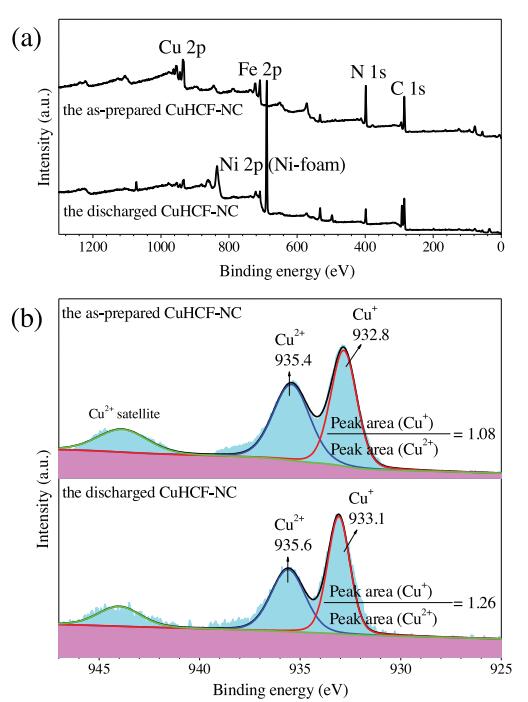
XPS measurement was performed to elucidate the valence change of Fe and Cu cations in the as-prepared and discharged CuHCF-NC samples. The survey spectra confirm the presence of Cu, Fe, N and C elements (Fig. 3a). The high-resolution spectra of Fe 2p3/2 (Fig. S5 in Supporting information) display the characteristic peaks at 710.0 and 708.4 eV, which correspond to the Fe3+ in [Fe(CN)6]3+ and Fe2+ in [Fe(CN)6]4+, respectively [36, 37]. In Fig. 3b, the binding energy peaks of Cu 2p3/2 located at 935.4 and 932.8 eV can be ascribed to the Cu2+ and Cu+ species, respectively [34]. And the peak area ratios (Cu+/Cu2+) are calculated to be 1.08 and 1.26 for the as-prepared and discharged CuHCF-NC materials, respectively. In comparison with the as-prepared CuHCF-NC material, the discharged CuHCF-NC demonstrates decreased intensity of Fe3+ and Cu2+ species as well as increased intensity of Fe2+ and Cu+ species. These results indicate that parts of Fe3+ and Cu2+ ions are reduced during the discharge process. Hence the pseudocapaci-tance of the CuHCF nanocubes can be attributed to the redox reactions of Fe3+/Fe2+ and Cu2+/Cu+ couples.

|
Download:
|
| Fig. 3. XPS spectra of the as-prepared and discharged CuHCF-NC samples: (a)survey spectra, (b) Cu 2p3/2 binding energy spectra. | |
As reported in literatures [31, 32], the electrochemical reactions of CuHCF in acidic and neutral aqueous electrolytes were written as the following Eqs. (1) and (2), respectively:

|
(1) |

|
(2) |
The charge storage of CuHCF was discussed in terms of the reversible redox reaction of Fe3+/Fe2+ couple. Typical CV curve showed one pair of redox peaks. As for the CuHCF nanocubes, the most impressed result is that its CV curves consist of two pairs of redox peaks, which cannot simply be attributed to the Faradaic redox reaction of Fe3+/Fe2+ couple. And the capacity contributions of both Fe3+/Fe2+ and Cu2+/Cu+ redox couples are confirmed by XPS. Therefore, a new charge storage mechanism is proposed that the CuHCF nanocubes undergo the reversible electrochemical oxida-tion and reduction of both Fe3+/Fe2+ and Cu2+/Cu+ couples to store charges. Na+ ions are inserted/extracted into/from the CuHCF framework to maintain charge neutrality during the discharge/ charge processes. As shown in Fig. 2a, the oxidation (reduction) peaks located at 0.57 (0.44) and 0.72 (0.60) V correspond to the electrochemical reactions of Fe3+/Fe2+ and Cu2+/Cu+ redox couples, respectively. The observation of electrochemically active Cu species in the CuHCF nanocubes may be interpreted to be due to the surface-adsorbed citrate ions. During the crystallization process of CuHCF nanocubes, the citrate ions can be adsorbed onto the surfaces because the carboxylate groups (COOH) of citrate ions form strong covalent interaction with Cu cations [38]. And the strong coordination interaction between citrate ions and surface Cu cations results in activating the Cu2+/Cu+ redox couple within the electrochemical stability potential window of aqueous electro-lytes (0.0–1.0 V vs. SCE). Very recently, it has been reported that the redox transition of the Cu2+/Cu+ couple is enhanced in 2.0 mol/L H2SO4 electrolyte when protons instead of Na+ or K+ cations are stored in the CuHCF framework [39]. Whereas in neutral aqueous electrolytes, the coordination-induced activation of the Cu2+/Cu+ redox couple is observed for the first time.
In summary, ordered CuHCF nanocubes with a size of 150– 350 nm have been synthesized by the conventional co-precipita-tion method with using potassium citrate as a chelating agent. The CuHCF nanocubes possessing high capacitances (285 F/g at 1 A/g) exhibit two pairs of well-defined cathodic and anodic CV peaks. On basis of CV and XPS analyses, electrochemically active Cu species are verified. And a charge storage mechanism is proposed that the CuHCF nanocubes undergo the electrochemical oxidation and reduction of Cu2+/Cu+ and Fe3+/Fe2+ couples during the processes of charge and discharge. This is the first report about the activation of Cu2+/Cu+ redox couple due to the coordination of citrate ions in neutral aqueous electrolytes for CuHCF.
AcknowledgmentThis work is supported by the National Natural Science Foundation of China (No. 51877029).
Appendix A. Supplementary dataSupplementary material related to this article can be found, in the online version, at doi:https://doi.org/10.1016/j.cclet.2019.07.022.
| [1] |
Y. Xu, S. Zheng, H. Tang, et al., Energy Storage Mater. 9 (2017) 11-30. DOI:10.1016/j.ensm.2017.06.002 |
| [2] |
Y. Xu, Q. Li, H. Xue, H. Pang, Coord. Chem. Rev. 376 (2018) 292-318. DOI:10.1016/j.ccr.2018.08.010 |
| [3] |
Y. Yan, B. Li, W. Guo, H. Pang, H. Xue, J. Power Sources 329 (2016) 148-169. DOI:10.1016/j.jpowsour.2016.08.039 |
| [4] |
B. Li, P. Gu, Y. Feng, et al., Adv. Funct. Mater. 27 (2017) 1605784. |
| [5] |
L. Yao, T. Cheng, X. Shen, et al., Chin. Chem. Lett. 29 (2018) 587-591. DOI:10.1016/j.cclet.2018.01.007 |
| [6] |
A. Lisowska-Oleksiak, A.P. Nowak, J. Power Sources 173 (2007) 829-836. DOI:10.1016/j.jpowsour.2007.05.046 |
| [7] |
J. Chen, K. Huang, S. Liu, Electrochem. commun. 10 (2008) 1851-1855. DOI:10.1016/j.elecom.2008.07.046 |
| [8] |
L. Zhou, M. Zhang, Y. Wang, et al., Electrochim. Acta 232 (2017) 106-113. DOI:10.1016/j.electacta.2017.02.096 |
| [9] |
K. Lu, D. Li, X. Gao, et al., J. Mater. Chem. A 3 (2015) 16013-16019. DOI:10.1039/C5TA04244E |
| [10] |
H. Pang, Y. Zhang, T. Cheng, W.Y. Lai, W. Huang, Nanoscale 7 (2015) 16012-16019. DOI:10.1039/C5NR04322K |
| [11] |
Y. Wang, H. Zhong, L. Hu, et al., J. Mater. Chem. A 1 (2013) 2621-2630. DOI:10.1039/c2ta01354a |
| [12] |
H. Jiang, Y.T. Xu, T. Wang, et al., Electrochim. Acta 166 (2015) 157-162. DOI:10.1016/j.electacta.2015.03.089 |
| [13] |
K. Krishnamoorthy, P. Pazhamalai, S. Sahoo, et al., Chem. Electro. Chem. 4 (2017) 1-8. |
| [14] |
F. Zhao, Y. Wang, X. Xu, et al., ACS Appl. Mater. Interfaces 6 (2014) 11007-11012. DOI:10.1021/am503375h |
| [15] |
K. Lu, B. Song, X. Gao, et al., J. Power Sources 303 (2016) 347-353. DOI:10.1016/j.jpowsour.2015.11.031 |
| [16] |
N.K.A. Venugopal, J. Joseph, J. Power Sources 305 (2016) 249-258. DOI:10.1016/j.jpowsour.2015.11.088 |
| [17] |
A.A. Ensafi, N. Ahmadi, B. Rezaei, RSC Adv. 5 (2015) 91448-91456. DOI:10.1039/C5RA17945A |
| [18] |
Y. Zou, Q. Wang, C. Xiang, et al., Electrochim. Acta 188 (2016) 126-134. DOI:10.1016/j.electacta.2015.11.123 |
| [19] |
P. Díaz, Z. González, R. Santamaría, et al., Electrochim. Acta 212 (2016) 848-855. DOI:10.1016/j.electacta.2016.07.057 |
| [20] |
D. Zhang, J. Zhang, Z. Yang, et al., Chem. Commun. 53 (2017) 10556-10559. DOI:10.1039/C7CC04914E |
| [21] |
X. Ma, X. Du, X. Li, et al., J. Alloys. Compd. 695 (2017) 294-301. DOI:10.1016/j.jallcom.2016.10.206 |
| [22] |
Y. Yang, Y. Hao, X. Wang, et al., Electrochim. Acta 167 (2015) 364-371. DOI:10.1016/j.electacta.2015.03.174 |
| [23] |
M. Sookhakian, W.J. Basirun, M.A.M. Teridi, et al., Electrochim. Acta 230 (2017) 316-323. DOI:10.1016/j.electacta.2017.02.022 |
| [24] |
Y. Yang, Y. Hao, J. yuan, L. Niu, F. Xia, Carbon 84 (2015) 174-184. DOI:10.1016/j.carbon.2014.12.005 |
| [25] |
J.G. Wang, Z. Zhang, X. Liu, B. Wei, Electrochim. Acta 235 (2017) 114-121. DOI:10.1016/j.electacta.2017.03.094 |
| [26] |
X. Zhang, L. Tao, P. He, et al., Electrochim. Acta 259 (2018) 793-802. DOI:10.1016/j.electacta.2017.11.007 |
| [27] |
L. Niu, L. Chen, J. Zhang, P. Jiang, Z. Liu, J. Power Sources 380 (2018) 135-141. DOI:10.1016/j.jpowsour.2018.01.083 |
| [28] |
S.T. Senthilkumar, J. Kim, Y. Wang, H. Huang, Y. Kim, J. Mater. Chem. A 4 (2016) 4934-4940. DOI:10.1039/C6TA00093B |
| [29] |
P. Pazhamalai, K. Krishnamoorthy, S. Sahoo, S.J. Kim, J. Alloys. Compd. 765 (2018) 1041-1048. DOI:10.1016/j.jallcom.2018.06.249 |
| [30] |
H. Yao, F. Zhang, G. Zhang, Y. Yang, Electrochim. Acta 294 (2019) 286-296. DOI:10.1016/j.electacta.2018.10.056 |
| [31] |
M.S. Wu, L.J. Lyu, J.H. Syu, J. Power Sources 297 (2015) 75-82. DOI:10.1016/j.jpowsour.2015.07.101 |
| [32] |
J. Li, H. Li, J. Li, et al., J. Power Sources 386 (2018) 96-105. DOI:10.1016/j.jpowsour.2018.03.046 |
| [33] |
E. Targholi, M.S. Rahmanifar, S.M. Mousavi-Khoshdel, Mousavi-Khoshdel, Appl. Organomet. Chem. 32 (2018) e4615. DOI:10.1002/aoc.4615 |
| [34] |
H. Draouil, L. Alvarez, J. Causse, et al., New J. Chem. 41 (2017) 7705-7713. DOI:10.1039/C7NJ00879A |
| [35] |
J.G. Wang, Z. Zhang, X. Zhang, et al., Nano Energy 39 (2017) 647-653. DOI:10.1016/j.nanoen.2017.07.055 |
| [36] |
K. Siuzdak, M. Szkoda, J. Karczewski, J. Ryl, A. Lisowska-Oleksiak, RSC Adv. 6 (2016) 76246-76250. DOI:10.1039/C6RA15113B |
| [37] |
P. Xiong, G. Zeng, L. Zeng, M. Wei, Dalton Trans. 44 (2015) 16746-16751. DOI:10.1039/C5DT03030G |
| [38] |
K.J. Westin, C. Å.Rasmuson, Desalination 159 (2003) 107-118. DOI:10.1016/S0011-9164(03)90063-4 |
| [39] |
X. Wu, J.J. Hong, W. Shin, et al., Nat. Energy 4 (2019) 123-130. DOI:10.1038/s41560-018-0309-7 |