 2020, Vol. 31


b Key Laboratory of Hunan Province for Efficient Power System and Intelligent Manufacturing, Shaoyang University, Shaoyang 422000, China
MXenes, a family of two-dimensional (2D) early transition metal carbides or nitrides, have attracted great attention recently owing to their unique 2D structure and properties. The general formula of MXenes is Mn+1XnTx, where M is an early transition metal, X is carbon or nitrogen, and T is surface functional group such as O, OH and F. Since the first MXene Ti3C2Tx has been discovered in 2011 [1], MXenes show promising potentials in numerous applications such as energy storage [2-7], catalysis [8-12], electromagnetic shielding [13-15], antibacterical [16, 17], memristive device [18-20], water purification [21]. Up to now, the major strategy for preparation of MXene few-layer flakes is etching MAX powders with HF or HCl and LiF, then followed by a delamination process such as sonication or hand shaking. However, the yield of MXene few-layer flakes via this two-step process is estimated lower than 20% in most situations [22], which may retard the steps of MXenes in real applications.
To overcome the challenge of low yield, some novel strategies were employed recently to boost the yield of Ti3C2Tx few-layer flakes. For example, a microwave-assisted etching method has been reported to apply in the preparation of Ti3C2Tx MXene, yet only a relatively low sheet yield of less than 10% was reached [23]. Furthermore, by using an electrochemical etching process in a binary aqueous system, high yield (>90%) of single or bilayer Ti3C2Tx flakes was achieved [24]. Nevertheless, this number is the percentage of monolayer and/or bilayer flakes among all the layered flakes after centrifugal separation, which does not reflect the real yield calculated by using the weight ratio of few-layer flakes to multiple-layer Ti3C2Tx precursor. Two other strategies are selective lithiation-expansion-microexplosion synthesis [25] and hydrothermal alkali treatment [26], demonstrating excellent effectiveness to obtain 2D Ti3C2Tx sheets, but the exact yield was kept unknown. Fortunately, a successful approach was reported that by adding a hydrothermal treatment before sonication process, a high yield of 74% was achieved [27]. However, to further save the cost of preparation of the Ti3C2Tx few-layer flakes, seeking simple and cost effective solutions to achieve high yield of MXenes is still a challenging topic for researchers.
Herein, we proposed a simple strategy to achieve relatively high yield of Ti3C2Tx few-layer flakes by decreasing the precursor size. In this work, Ti3AlC2 powders with three different sizes (300 mesh, 400 mesh and 500 mesh) were used as precursors. When etching the smallest one (500 mesh Ti3AlC2 powders) with HCl and LiF at 35 ℃, we received as high as 65% Ti3C2Tx few-layer flakes of the received Ti3C2Tx MXene product. In addition, the as-received Ti3C2Tx few-layer flakes show better electrical conductivity, a more expanded interlayer space, more O content on the surface compared to other two products etched from bigger Ti3AlC2 powders, resulting in an enhanced pseudocapacitor performance.
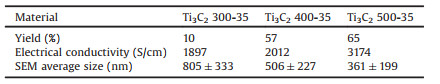
The yields of few-layer Ti3C2Tx flakes etched from Ti3AlC2 powders with different sizes at different conditions are showed in Table 1. Ti3C2 300-35, Ti3C2 400-35 and Ti3C2 500-35 are named as the products etched from 300 mesh, 400 mesh and 500 mesh Ti3AlC2 powders at 35 ℃ respectively. The detailed experimental is shown in the supplementary information. As expected, the size of starting Ti3AlC2 powders exhibited important effect on the final yield. A remarkably high yield of 65% is achieved when using 500 mesh Ti3AlC2 as raw material, which is much higher than the yield of using 300 mesh Ti3AlC2 as raw material. The highest yield (65%) of this work is very close to the yield (74%) of hydrothermalassisted intercalation method [27], and much higher than the 20% yield claimed by other research [22, 28]. Particularly, this strategy is simple, cost effective and suitable for mass production. For example, the 500 mesh Ti3AlC2 MAX powders is convenient to obtain through a facile ball milling process. Table 1 also shows the electrical conductivity of different Ti3C2Tx films. All the films exhibit excellent electrical conductivity as other reported Ti3C2Tx MXene films, particularly in which Ti3C2 500-35 film has the best value of 3174 S/cm.
|
|
Table 1 The yield and properties of the materials under study. |
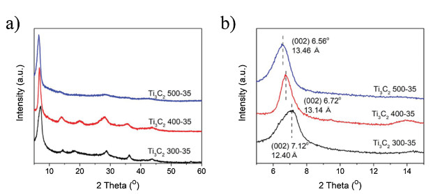
Interestingly, the size of starting Ti3AlC2 powders also show obvious effect to the composition and structure of the received few-layer Ti3C2Tx flakes. As shown in Fig. 1, all the etched samples exhibited similar XRD spectra to those of delaminlated Ti3C2 MXenes reported in literature [11, 18, 29], indicating the thoroughly removal of Al and the establishment of surface functional groups, such as –O, –OH and –F. It can be clearly seen in Fig. 1b that the characteristic (002) peak of Ti3C2Tx shifts from 7.12° to a lower anger of 6.56° with the decreasing of the Ti3AlC2 precursors size, suggesting the interlayer space expanded from 12.40 Ǻ to 13.14 Ǻ. This expansion probably origins from the decreased Ti3C2Tx flakes [30], which have more surface functional groups or more intercalated water molecules between adjacent layers.

|
Download:
|
| Fig. 1. XRD patterns of different few-layer Ti3C2Tx films. | |
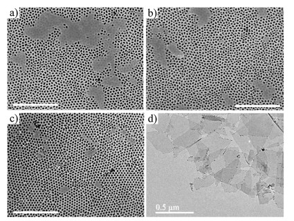
Except the interlayer space between Ti3C2Tx flakes, the flake size also has important effect on the electrochemical performance of Ti3C2Tx MXene [30, 31]. Thus the flakes etched from the Ti3AlC2 precursors with different sizes have been investigated by SEM, shown in Figs. 2a–c. Calculated at least a hundred flakes in SEM images of each sample, the average sizes of Ti3C2Tx flakes of Ti3C2 300-35, Ti3C2 400-35 and Ti3C2 500-35 are 805 nm, 506 nm and 361 nm, respectively (Table 1). In addition, The Ti3C2Tx flakes of Ti3C2 500-35 in TEM image (Fig. 2d) show a transparent morphology, indicating most of the received flakes are singlelayer or few-layer.

|
Download:
|
| Fig. 2. SEM micrographs of different few-layer Ti3C2Tx flakes: (a) Ti3C2 300-35; (b) Ti3C2 400-35; (c) Ti3C2 500-35 (Scale bar =2 μm). (d) TEM micrograph of Ti3C2Tx flakes of Ti3C2 500-35 (Scale bar =0.5 μm). | |
To study the surface functional groups on Ti3C2Tx flakes, X-ray photoelectron spectroscopy (XPS) was applied to compare the different samples (Fig. 3). High resolution C 1s and Ti 2p spectra of all three samples are very similar, showing that the three samples have similar surface structure. However, compared to Ti3C2 300-35 flakes, the O 1s spectra of Ti3C2 400-35 flakes and Ti3C2 500-35 flakes exhibit some obvious changes. The enhancement of the C–Ti–O, C–Ti–(OH)x and C–Ti–(OH)x·H2O bonds, which are located at 530.6, 532.1 and 533.1 eV, respectively [27, 32, 33], indicates the increase of –OH and –O terminations. This increase is also proved by the spectra of Ti 2p, which show an significant enhancement of Ti3+ peak at 457.2 eV in Ti3C2 500-35 flakes. In addition, the element contents of different samples measured by XPS are shown in Fig. 3d. The O content of Ti3C2 300-35, Ti3C2 400-35 and Ti3C2 500-35 flakes is 14.84%, 17.37% and 18.88%, respectively. Meanwhile, the F content of Ti3C2 300-35, Ti3C2 400-35 and Ti3C2 500-3 flakes is 12.42%, 13.55% and 9.40%, respectively, showing an inverse trend compared to O contents. Note although the F content of Ti3C2 400-35 is higher than that of Ti3C2 300-35, the O/F ratio of Ti3C2 400-35 is still increased compared to Ti3C2 300-35, suggesting –O or –OH groups occupied more surface area of Ti3C2Tx flakes in Ti3C2 400-35. In addition, if considering the Ti contents of the three samples, the (O + F)/Ti ratio of Ti3C2 300-35, Ti3C2 400-35 and Ti3C2 500-35 flakes is 1.025, 1.149 and 1.178, respectively, indicating there are more surface functional groups on smaller flakes. Combining the results of element contents and XPS spectra, we can conclude that by decreasing the Ti3AlC2 precursor size, the surface –F functional groups can be removed or substituted by –O/–OH functional groups, resulting in more O contents in smaller Ti3C2Tx flakes. This change may be attributed to the choice of free energy of Ti3C2Tx. For the 2D Ti3C2Tx flakes, the surface functional groups contribute to their free energy via three interactions: adsorption site, in-plane distribution pattern and surface-surface correlation, and the adsorption site is the most important one [34]. However, although –O terminated Ti3C2Tx is the most energetically favorable [34], the surface functional groups on Ti3C2Tx flakes in most situations are the mixture of –O, –OH and F because they strongly prefer mixing to segregating [35] due to the in-plane distribution pattern. Thus when Ti3C2Tx flakes become smaller and thinner, –O termination will probably increase because there are less in-plane distribution pattern and surface-surface correlation interactions. In addition, -OH termination may also increase because it tends to transfer to –O termination [34].

|
Download:
|
| Fig. 3. High resolution C 1s (a), O 1s (b) and Ti 2p (c) XPS spectra of Ti3C2 300-35, Ti3C2 400-35 and Ti3C2 500-35. (d) Element distribution of the samples measured by XPS. | |
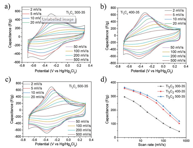
Finally, cyclic voltametry (CV) and galvanostatic chargedischarge (GCD) experiments in a three-electrode system in 3 mol/L H2SO4 were performed to examine the electrochemical performance of these samples. The CV curves and capacitances of the Ti3C2 300-35, Ti3C2 400-35 and Ti3C2 500-35 film electrode are shown in Fig. 4. It has been proved previously that the pseudocapacitance of Ti3C2Tx is mainly attributed to the protonation of oxygen functional groups on its surface, leading to the variation in the oxidation state of the surface titanium atoms [6, 36, 37]. For the three investigated electrodes, at a low scan rate of 2 mV/s, a pair of anodic and cathodic peaks near -0.35 V with small peak separations were detected, indicating the protonation and deprotonation process on the surface of Ti3C2Tx flakes. Particularly, benefiting from the excellent electrical conductivity and more interlayer water molecules, the CV curves of Ti3C2 500-35 film electrode exhibit a smallest peak separation among all three electrodes (Fig. S1). Moreover, this electrode shows the highest gravimetric capacitance of 364 F/g at a 2 mV/s scan rate (Fig. 4d). However, the capacitance of the electrodes markedly decreases as the flake sizes become bigger and the lowest capacitance of 296 F/g was obtained for an electrode prepared by Ti3C2 300-35 MXene flakes with the biggest average size of 805 nm. The capacitance (357 F/g) of Ti3C2 400-35 at a 2 mV/s scan rate is very close to that of Ti3C2 500-35, while it drops quicker than Ti3C2 500-35 as the scan rate increased. In addition, Ti3C2 500-35 electrode shows a stable cyclic performance, demonstrating an 88% capacitance retention after 10, 000 cycles Fig. S2 in Supporting information.

|
Download:
|
| Fig. 4. Electrochemical performance of different few-layer Ti3C2Tx film electrodes in three-electrode system. Cyclic voltammetry profiles of (a) Ti3C2 300-35, (b) Ti3C2 400-35, (c) Ti3C2 500-35. (d) Rate performance of different few-layer Ti3C2Tx film electrodes. | |
Note that the capacitor performance of our samples exhibit different results with flakes size variation compared to previous reports [30, 31], which show a down trend of the capacitance with the decrease with flakes lateral size (≤ 1 μm) at a low scan rate of 2 mV/s because the Ti3C2Tx film assembled by bigger flakes has better electrical conductivity. More interfacial contact resistance and higher number of defects introduced by sonication in smaller flakes are ascribed to the loss of conductivity [31, 38]. However, in our experiments, the Ti3C2 500-35 film with smallest lateral size among all the samples has best electrical conductivity of 3174 S/cm. First of all, these samples have roughly the same number of defects because they went through the same sonication process. Furthermore, surface functional groups on Ti3C2Tx flakes play an important role on the electrical conductivity [39-41], and the increase of -O terminations and decrease -F terminations may benefit to the value of conductivity [39]. On the basis of XPS results, Ti3C2 500-35 has the highest number of O content and lowest number of F content, and these O content exist in Ti3C2Tx flakes as –O and –OH terminations revealed by O 1s and Ti 2p spectra of Ti3C2Tx samples (Fig. 3), which may benefit to the enhancement of electrical conductivity. On the other hand, it has been proved that the pseudocapacitance of 2D Ti3C2Tx sheets is associated with the change of Ti oxidation state, which change is accompanied by the protonation of -O groups [5, 6, 36, 37, 42], thus Ti3C2 500-35 film electrode has highest capacitance among all the received samples, confirmed by the sharper peaks of Ti3C2 500-35 close to -0.35 V compared to those of Ti3C2 300-35 and Ti3C2 400-35 [36]. In addition, benefiting from the better ion accessibility [30] and more high-mobility water molecules between Ti3C2Tx interlayers of smaller flakes, which have been proved can fasten the diffusion of hydrogen ions between MXene interlayers [43], Ti3C2 500-35 film electrode also deliver better rate performance than other two samples.
In summary, we have demonstrated that the precursor size of 2D Ti3C2Tx sheets play a very important role to their yield, structure and electrochemical performance. By using the small 500 mesh Ti3AlC2 powders as precursor, a high yield of 65% Ti3C2Tx MXene few-layer flakes was achieved through etching Ti3AlC2 with HCl and LiF. Furthermore, the small Ti3C2Tx flakes has better electrical conductivity, more O content and interlayer water molecules compared to the products etched from 300 mesh and 400 mesh Ti3AlC2 powders, thus delivering higher capacitance and better rate performance than the other two Ti3C2Tx flakes when using as capacitor electrodes. A high capacitance of 364 F/g and an 88% capacitance retention after 10, 000 cycles were achieved as a result. Our results presented here are applicable to the mass production of 2D MXenes materials and make them promising cost effective electrode materials in real energy storage related applications.
Declaration of competing interestThe authors declare that they have no known competing financial interests or personal relationships that could have appeared to influence the work reported in this paper.
AcknowledgmentsJ. Xu thanks the National Natural Science Foundation of China (No. 21671167) and the Joint Open Fund of Jiangsu Collaborative Innovation Center for Ecological Building Material and Environmental Protection Equipments and Key Laboratory for Advanced Technology in Environmental Protection of Jiangsu Province (No. JH201847). W. Yao thanks the National Natural Science Foundation of China (No. 51602277).
Appendix A. Supplementary dataSupplementary material related to this article can be found, in the online version, at doi:https://doi.org/10.1016/j.cclet.2020.02.050.
| [1] |
M. Naguib, M. Kurtoglu, V. Presser, et al., Adv. Mater. 23 (2011) 4248-4253. DOI:10.1002/adma.201102306 |
| [2] |
M. Naguib, J. Come, B. Dyatkin, et al., Electrochem. Commun. 16 (2012) 61-64. DOI:10.1016/j.elecom.2012.01.002 |
| [3] |
M.R. Lukatskaya, O. Mashtalir, C.E. Ren, et al., Science 341 (2013) 1502-1505. DOI:10.1126/science.1241488 |
| [4] |
M. Naguib, J. Halim, J. Lu, et al., J. Am. Chem. Soc. 135 (2013) 15966-15969. DOI:10.1021/ja405735d |
| [5] |
J. Yan, C.E. Ren, K. Maleski, et al., Adv. Funct. Mater. (2017) 1701264. |
| [6] |
M.R. Lukatskaya, S. Kota, Z. Lin, et al., Nat. Energy 6 (2017) 17105. |
| [7] |
Y. Liu, P. Zhang, N. Sun, et al., Adv. Mater. 30 (2018) 1707334. DOI:10.1002/adma.201707334 |
| [8] |
S. Li, P. Tuo, J. Xie, et al., Nano Energy 47 (2018) 512-518. DOI:10.1016/j.nanoen.2018.03.022 |
| [9] |
Z. Li, Y. Wu, Small (2019) 1804736. |
| [10] |
A.D. Handoko, S.N. Steinmann, Z.W. Seh, Nanoscale Horiz. 4 (2019) 809-827. DOI:10.1039/C9NH00100J |
| [11] |
C. Liu, Q. Xu, Q. Zhang, et al., J. Mater. Sci. 54 (2019) 2458-2471. DOI:10.1007/s10853-018-2990-0 |
| [12] |
X. Xie, Z. Wu, N. Zhang, Chin. Chem. Lett. (2019). DOI:10.1016/j.cclet.2019.10.012 |
| [13] |
S. Zhao, H. Zhang, J. Luo, et al., ACS Nano 12 (2018) 11193-11202. DOI:10.1021/acsnano.8b05739 |
| [14] |
J. Liu, H. Zhang, R. Sun, et al., Adv. Mater. (2017) 1702367. |
| [15] |
F. Shahzad, M. Alhabeb, C.B. Hatter, et al., Science 353 (2016) 1137-1140. DOI:10.1126/science.aag2421 |
| [16] |
K. Rasool, M. Helal, A. Ali, et al., ACS Nano 10 (2016) 3674-3684. DOI:10.1021/acsnano.6b00181 |
| [17] |
E.A. Mayerberger, R.M. Street, R.M. McDaniel, M.W. Barsoum, C.L. Schauer, RSC Adv. 8 (2018) 35386-35394. DOI:10.1039/C8RA06274A |
| [18] |
M. Zhang, Y. Wang, F. Gao, et al., Ceram. Int. 45 (2019) 19467-19472. DOI:10.1016/j.ceramint.2019.06.202 |
| [19] |
Y. Chen, Y. Wang, Y. Luo, et al., IEEE Electr. Device Lett. 40 (2019) 1686-1689. DOI:10.1109/LED.2019.2936261 |
| [20] |
N. He, X. Liu, F. Gao, et al., Mater. Lett. 266 (2020) 127413. DOI:10.1016/j.matlet.2020.127413 |
| [21] |
X. Xie, C. Chen, N. Zhang, et al., Nat. Sustain. 2 (2019) 856-862. DOI:10.1038/s41893-019-0373-4 |
| [22] |
J. Xuan, Z. Wang, Y. Chen, et al., Angew. Chem. Int. Ed. 128 (2016) 14789-14794. DOI:10.1002/ange.201606643 |
| [23] |
W. Wu, J. Xu, X. Tang, et al., Chem. Mater. 30 (2018) 5932-5940. DOI:10.1021/acs.chemmater.8b01976 |
| [24] |
S. Yang, P. Zhang, F. Wang, et al., Angew. Chem. Int. Ed. 57 (2018) 15491-15495. DOI:10.1002/anie.201809662 |
| [25] |
Z. Sun, M. Yuan, L. Lin, et al., ACS Mater. Lett. (2019) 628-632. |
| [26] |
T. Li, L. Yao, Q. Liu, et al., Angew. Chem. Int. Ed. 57 (2018) 6115-6119. DOI:10.1002/anie.201800887 |
| [27] |
F. Han, S. Luo, L. Xie, et al., ACS Appl. Mater. Interfaces 11 (2019) 8443-8452. DOI:10.1021/acsami.8b22339 |
| [28] |
X. Cai, Y. Luo, B. Liu, H. Cheng, Chem. Soc. Rev. 47 (2018) 6224-6266. DOI:10.1039/C8CS00254A |
| [29] |
M. Ghidiu, M.R. Lukatskaya, M. Zhao, Y. Gogotsi, M.W. Barsoum, Nature 516 (2014) 78-171. DOI:10.1038/nature13970 |
| [30] |
E. Kayali, A. VahidMohammadi, J. Orangi, M. Beidaghi, ACS Appl. Mater. Interfaces 10 (2018) 25949-25954. DOI:10.1021/acsami.8b07397 |
| [31] |
K. Maleski, C.E. Ren, M. Zhao, B. Anasori, Y. Gogotsi, ACS Appl. Mater. Interfaces 10 (2018) 24491-24498. DOI:10.1021/acsami.8b04662 |
| [32] |
A. Qian, J.Y. Seo, H. Shi, J.Y. Lee, C. Chung, ChemSusChem 11 (2018) 3719-3723. DOI:10.1002/cssc.201801759 |
| [33] |
X. Chen, Y. Zhu, M. Zhang, et al., ACS Nano 13 (2019) 9449-9456. DOI:10.1021/acsnano.9b04301 |
| [34] |
T. Hu, M. Hu, B. Gao, W. Li, X. Wang, J. Phys. Chem. C 122 (2018) 18501-18509. DOI:10.1021/acs.jpcc.8b04427 |
| [35] |
R. Ibragimova, M.J. Puska, H. Komsa, ACS Nano 13 (2019) 9171-9181. DOI:10.1021/acsnano.9b03511 |
| [36] |
M. Hu, Z. Li, T. Hu, et al., ACS Nano 10 (2016) 11344-11350. DOI:10.1021/acsnano.6b06597 |
| [37] |
Y. Dall'Agnese, M.R. Lukatskaya, K.M. Cook, et al., Electrochem. Commun. 48 (2014) 118-122. DOI:10.1016/j.elecom.2014.09.002 |
| [38] |
C.J. Zhang, S. Pinilla, N. McEvoy, et al., Chem. Mater. 29 (2017) 4848-4856. DOI:10.1021/acs.chemmater.7b00745 |
| [39] |
J.L. Hart, K. Hantanasirisakul, A.C. Lang, et al., Nature Commun. 10 (2019) 522. DOI:10.1038/s41467-018-08169-8 |
| [40] |
Y. Xie, P.R.C. Kent, Phys. Rev. B 87 (2013) 235441. DOI:10.1103/PhysRevB.87.235441 |
| [41] |
T. Hu, Z. Li, M. Hu, et al., J. Phys. Chem. C 121 (2017) 19254-19261. DOI:10.1021/acs.jpcc.7b05675 |
| [42] |
M.R. Lukatskaya, S. Bak, X. Yu, et al., Adv. Energy Mater. 5 (2015) 1500589. DOI:10.1002/aenm.201500589 |
| [43] |
M. Hu, T. Hu, Z. Li, et al., ACS Nano 12 (2018) 3578-3586. DOI:10.1021/acsnano.8b00676 |