 2020, Vol. 31


b Key Laboratory of Materials Processing and Mold(Zhengzhou University), Ministry of Education, Zhengzhou University, Zhengzhou 450002, China;
c College of Mechanical and Electrical Engineering, Central South University, Changsha 410083, China
Lithium-ion batteries (LIBs) have been regarded as one of the most promising power sources in energy conversion and storage, due to their long cycle life and high energy density [1, 2]. However, the most widely used anode material, graphite, only possesses a limited capacity of 372 mAh/g [3, 4], which will not satisfy the requirements needed to power and develop next-generation electronic devices. Hence, it is one of the main challenges to design anode materials with high capacity, long cycling perfor-mance and offer a suitable voltage platform [5, 6].
To date, many materials such as carbon, metals, oxides, chalcogenides have been used as potential anode materials for LIBs [7-10]. Many nanomaterials have also attracted more attention due to their great mechanical, electrical properties and synergistic effects [11-15]. Among these materials, the metallic antimony (Sb) and Sb-based materials (oxides, chalcogenides and alloys) are of particular focus with the literature [16-20]. Prikhodchenko and co-workers designed an antimony sulfide coated reduced graphene oxide (rGO) that exceeded 720 mAh/g after 50 cycles at a current density of 250 mA/g [21]. Additionally, Park's group fabricated SnSb-CNT nanocomposite by reductive precipitation of metal chloride salts within a CNT suspension, which possessed a reversible capacity of 480 mAh/g after 50 cycles of the LIBs [22]. As one of the typical group V VI compounds, antimony selenide (Sb2Se3) is a p-type semiconductor with direct band-gap, and has widely been applied within optics, thermoelec-tric, electrochemical energy storage to name a few [23-25]. Regarding anode material for LIBs, 1 mol Sb2Se3 could accommo-date 12 mol Li+ during the lithiation/delithiation reaction, exhibit-ing a theoretical specific capacity of 670 mAh/g for LIBs. However, Sb2Se3 suffers some significant hindrances, such as aggregation, pulverization, loss of electrical contact due to the dramatic volume expansion during the lithiation/delithiation process. To solve the aforementioned problems, introduction of a carbon matrix allows for the Sb2Se3 to offer good performance, which can not only release the stress induced by the volume expansion of materials, but also alleviate agglomeration [26]. Although these promising results have already been obtained, further improvement can still be exhibited within the electrochemical performance.
In this work, we have reported Sb2Se3@C nanofibers (Sb2Se3@CNFs), synthesized by electrospinning method, as an anode for LIBs. One-dimensional (1D) nanofibers offer the advantage of continuous ion/electron channels, short diffusion distance and better contact between materials and current collectors, leading to an improved rate performance [27]. Additionally, these carbon nanofibers can prevent the huge volume changes during charge/discharge process as they provide a buffer layer, which enhances their overall cycling life [26]. Furthermore, the annealing temperatures were also optimized. Hence, when used as the anode for LIBs, the Sb2Se3@CNF annealed at 600 ℃ (Sb2Se3@CNF-600) could deliver remarkably high reversible capacities of 625 mAh/g at 100 mA/g after 100 cycles and 437 mAh/g at a large current density of 1.0 A/g after 500 cycles.
The synthesis process of the Sb2Se3@CNFs is as follows: 0.4936 g sodium antimonite (NaSbO3 3H2O, Tianjin Heowns Biochemical Technology Co., Ltd., China) and 0.45 g polyacryloni-trile (PAN, Mw = 150, 000, Sigma-Aldrich Co., Ltd., USA) were dissolved in 4.5 g N, N-dimethylformamide (DMF) solvent at room temperature with vigorous stirring for 2 h. Then, 0.3948 g Se powder (Aladdin Industrial Corporation, Ltd., USA) was added into the solution and kept vigorous stirring for 12 h. The as-prepared precursor solution was transferred into a 10-mL syringe connected to a stainless steel needle. A high voltage power supply was used to provide a 12 kV high voltage for the resulting precursor. The distance was about 12 cm between the needle and the collector, and the feed speed rate was set up at 0.4 mL/h. After that, the prepared nanofibers were dried at 60 ℃ for 12 h in vacuum oven. Afterward, the fibers were annealed in a tube furnace under Ar atmosphere at 500 ℃, 600 ℃, 700 ℃ for 2 h with a heating rate of 3 ℃/min, respectively. These samples were marked as Sb2Se3@CNF-500, Sb2Se3@CNF-600 and Sb2Se3@CNF-700, respec-tively. The produced nanofibers were washed by distilled water and ethanol for several times after dipping in the acetic acid solution for 24 h. Finally, the Sb2Se3@CNFs were collected after drying overnight in the air. And the N-doped C nanofibers (NCNFs) were prepared according the same process except without sodium antimonite and selenium powder.
The X-ray diffraction (XRD, Rigaku D/MAX-2500) was utilized to determine the phase composition and purity of the as-prepared composites. The morphology and structure of Sb2Se3@CNFs were analyzed by scanning electron microscopy (SEM, Hitachi S4800) and transmission electron microscopy (TEM, JEOL 2010). To confirm Sb2Se3 content in the samples, the thermogravimetric analysis (TGA, Setaram 018124) of the samples was carried out in air atmosphere from 30 ℃ to 800 ℃ with a heating rate of 10 ℃/min. The surface area and pore width distribution of the sample were performed by Brunauer–Emmett–Teller (BET, Micro-meritics ASAP 2460) with the adsorption of N2. X-ray photoelectron spectroscopy (XPS, Thermo Scientific Escalab 250Xi, USA) was used to research the element composition and chemical bonds of the samples.
Electrochemical performance was investigated by using CR-2025 coin-type cells. The tested coin cells were assembled in a pure argon gas glove box with the contents of H2O and O2 less than 0.5 ppm. And the working electrodes were prepared as following: Active material (80 wt%), acetylene carbon black (10 wt%) and carboxylmethyl cellulose (CMC, 10 wt%) were mixed together and dispersed in a mixed solvent of ethanol and distilled water, in order to form a uniform slurry. Subsequently, the mixed slurry was coated on copper foil and dried at 60 ℃ for 24 h. Generally, the average active material mass loading was controlled about 1.0 mg/cm2. The counter electrode was Li metal. The electrolyte was 1.0 mol/L LiPF6 dissolving in a 1:1 volumetric mixture of ethylene carbonate (EC) and dimethyl carbonate (DMC). Galvano-static charge–discharge testing was carried on a Neware battery testing system in a voltage window of 0.01–3 V. Cyclic voltam-metry measurements (CV) and electrochemical impedance spec-troscopy (EIS) were performed by using a CHI 660e electrochemical workstation.
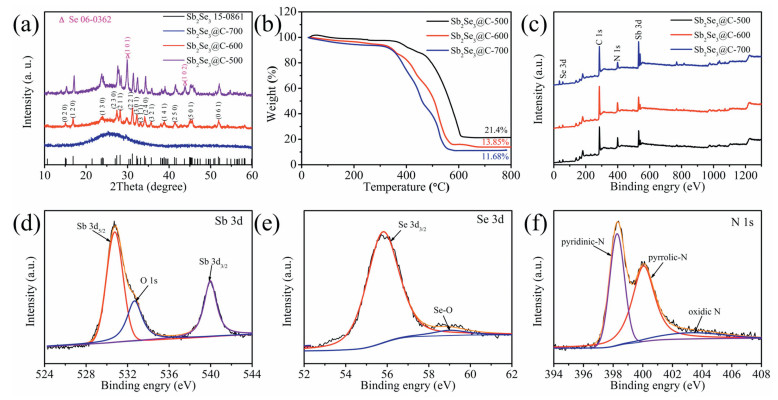
The crystal structures of Sb2Se3@CNFs annealed at the different temperatures were characterized by XRD (Fig. 1a). It is obvious that all diffraction peaks of Sb2Se3@CNF-600 correspond well to the orthorhombic Sb2Se3 phase with the space group Pbnm (JCPDS No.15-0086) [18, 28]. The 2θ values of the main peaks are located at 15.02°, 16.88°, 23.9°, 27.38°, 28.20°, 31.16°, 32.22°, 33.10°, 34.06°, 35.68°, 38.8°, 41.3°, 45.06° and 51.88° which corresponded to the (020), (120), (130), (230), (221), (301), (311), (240), (321), (141), (250), (501) and (061) lattice planes of orthorhombic Sb2Se3, respectively. On the contrary, Sb2Se3@CNF-500 possesses other crystal phases. Among them, the diffraction peaks at 29.74°, 43.64° are associated with the (101), (102) lattice planes of Se (JCPDS No. 06-0362). Such lattice planes could be due to the separation of the reactants during the electrospinning process, and thus do not react well at 500 ℃, resulting in the existence of Se. The Sb2Se3@CNF-700 has no obvious diffraction peak for Sb2Se3, but only possesses a broad carbon peak (JCPDS No. 03-0401). This might be ascribed to the least Sb2Se3 content of Sb2Se3@CNF-700. And the crystallite size of Sb2Se3 can be calculated with the Scherer equation of D = kλ/(βcosθ), where θ is the Bragg angle in degrees; D is the size of crystallites; k is the shape factor of 0.89; λ is the X-ray wavelength of 1.54 Å and β is the fwhm of the reflection peaks [29]. The calculated average crystallite sizes are 26.81 and 22.08 nm for Sb2Se3@CNF-500 and Sb2Se3@CNF-600, respectively. The grain size is one of the important factors for lithium storage: the smaller the particle size benefits the mobility of Li ions [30]. Hence, the grain size of Sb2Se3@CNF-600 is better than Sb2Se3@CNF-500.

|
Download:
|
| Fig. 1. (a) XRD patterns, (b) TGA curves, (c) XPS spectra of all elements of Sb2Se3@CNF, (d) Sb 3d, (e) Se 3d and (f) N 1s of Sb2Se3@CNF-600. | |
The Sb2Se3 contents in Sb2Se3@CNFs were carried out by TGA (Fig. 1b). The gradual decrease at the start of the curves (i.e., below 200 ℃) can be observed, due to the evaporation of water [31]. Upon the oxidation of Sb2Se3 to Sb2O4 and formation of SeO2 and CO2, the weights of the Sb2Se3@CNFs rapidly decreased over the tempera-ture range of 350–600 ℃. The oxidation reaction is: Sb2Se3 + 5O2 = Sb2O4 + 3SeO2↑ [7, 28]. From the result of TGA, the Sb2Se3 content of Sb2Se3@CNF-500/600/700 can be calculated as 33.43%, 21.64% and 18.24%, respectively. It is clear that the Sb2Se3 content of Sb2Se3@CNF-500/600/700 became less with the higher annealing temperatures.
To obtain the information about the elemental valences and compositions, the as-prepared products were characterized further by XPS, and results are depicted in Figs. 1c–f and Fig. S1 (Supporting information). The whole XPS spectra (Fig. 1c) reveals the existence of Sb, Se, C and N elements in all the samples tested. The high-resolution peaks of the Sb 3d in Fig. 1d can be divided into three significant peaks of 530.76 eV, 532.66 eV and 539.96 eV, respectively. Moreover, the peaks of 530.76 eV and 539.96 eV correspond to Sb 3d5/2 and Sb 3d3/2, respectively, indicating the presence of Sb3+ in the Sb2Se3@CNF-600. It should be noted that the peak of 532.66 eV is present due to a small account of surface oxidation of the Sb2Se3, relating to the O 1s [31, 32]. Presented in Fig. 1e, are peaks positioned at 55.79 eV and 58.98 eV that are related to Se 3d3/2 and Se-O bond, meaning the presence of Se2- in the Sb2Se3@CNF-600 nanofibers is evident [32, 33]. The high-resolution peaks of Sb 3d and Se 3d of Sb2Se3@CNF-500 and Sb2Se3@CNF-700 were displayed in Figs. S1a-e, exhibiting similar spectra to the Sb2Se3@CNF-600. Furthermore, the peaks of the C 1s in the Sb2Se3@C-500, Sb2Se3@C-600 and Sb2Se3@C-700 could be resolved into three binding energies, shown in Figs. S1g-i. The peak located at 284.77 eV, 286.36 eV and 288.88 eV correspond to the C—C, C—O and C=O bond, respectively [7, 34]. In addition, the high-resolution N 1s spectra of Sb2Se3@CNF-600 in Fig. 1f can be attributed to pyridinic-N, pyrrolic-N and oxidic-N, which appears at ~398.26 eV, 400.05 eV and 403.23 eV, respectively. While the N 1s spectra of Sb2Se3@CNF-500 and Sb2Se3@CNF-700 are demonstrated in Figs. S1c and f, with the relative content of each nitrogen type being shown in Table S1 (Supporting information). It is proved that N-doped carbon materials have a higher capacity. First, because the doped N can offer more electrons to the π-conjugated system of carbon, enhance the electronic properties of neighboring carbon atoms, then strengthen the electronic conductivity of carbon nanofibers [35]. Secondly, the electronega-tivity of nitrogen is higher than carbon and then produces more binding sites for Li ions [36]. And that the carbon atoms around the nitrogen atoms have become more electronegative to adsorb more Li ions in these areas. On the other hand, pyridinic-N and pyrrolic-N create more open channels and defects in carbon due to N substitution for more Li+ insertion [37-39]. The high content of pyridinic-N and pyrrolic-N will therefore benefits the Li+ storage properties of the Sb2Se3@CNF. The overall content of pyridinic-N and pyrrolic-N within the Sb2Se3@CNF-600 is the highest, which can help Li+ storage in sample. Similarly, with the results of XRD and TGA, the characterization of XPS also indicates that 600 ℃ is the most appropriate annealing temperature.
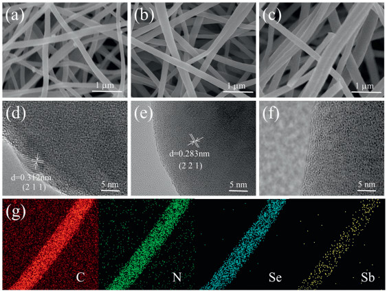
The morphologies of the as-obtained Sb2Se3@CNF-500, Sb2Se3@CNF-600, Sb2Se3@CNF-700 and NCNFs were characterized by SEM, TEM and HR-TEM (Figs. 2a–f, Figs. S2 and S3 in Supporting information), respectively. The SEM images of Sb2Se3@CNF-500, Sb2Se3@CNF-600 and Sb2Se3@CNF-700 in Figs. 2a–c reveal the nanofiber-like morphology that displays individual and uniform nanofibers with a diameter of ~150-200 nm, which is also confirmed by the TEM images (Figs. S2d-f). As exhibited in the HR-TEM images (Figs. 2d–f), there are lattice fringes with distances of 0.312 nm and 0.283 nm for the Sb2Se3@CNF-500 and Sb2Se3@CNF-600 corresponding to the (2 1 1) plane and (2 2 1) plane of orthorhombic Sb2Se3 (JCPDS No. 15-0086), indicating that Sb2Se3 exists within the carbon nanofibers. The electron diffraction X-ray spectroscopy (EDS) spectra of Sb2Se3@CNF-600 in Fig. 2g demon-strate the C, N, Se, Sb elements distribution within the nanofibers. The flexible matrix consisting of 1D nanofibers offers the advantages of continuous ion/electron channels and short diffu-sion distances, and also prevents the huge volume changes during charge/discharge process acting as a buffering layer [27, 40]. Thus, the structure of Sb2Se3@CNFs will facilitate them to enhance both the rate performance and cycling life.

|
Download:
|
| Fig. 2. (a–c) SEM images of Sb2Se3@CNF-500, Sb2Se3@CNF-600, and Sb2Se3@CNF-700; (d–f) HR-TEM images of Sb2Se3@CNF-500, Sb2Se3@CNF-600, and Sb2Se3@CNF-700; (g) EDS spectra of Sb2Se3@CNF-600. | |
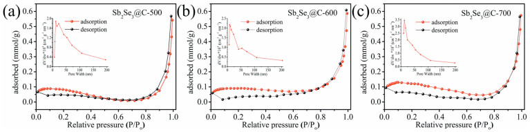
BET analysis was carried out to study the specific surface area of the Sb2Se3@CNFs. Fig. 3 and Table S2 (Supporting information) show the nitrogen adsorption–desorption isotherms, pore width and specific surface area of Sb2Se3@CNF-500, Sb2Se3@CNF-600 and Sb2Se3@CNF-700, which are about 4.62 m2/g, 6.07 m2/g and 7.58 m2/g, respectively. The more irreversible solid electrolyte interphase (SEI) is formed due to the larger specific surface area. In addition to this, higher pore width can lead to a higher irreversible Li storage and then present poor cycling performance [41]. The suitable specific surface area can make Sb2Se3@CNFs exhibit excellent performance for LIBs.

|
Download:
|
| Fig. 3. (a–c) N2 adsorption–desorption isotherm of Sb2Se3@CNF-500, Sb2Se3@CNF-600, Sb2Se3@CNF-700, respectively. The inset is the pore width of corresponding samples. | |
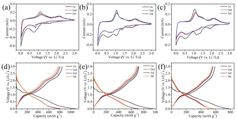
The electrochemical performances of the Sb2Se3@CNF-500, Sb2Se3@CNF-600 and Sb2Se3@CNF-700 as anode materials for LIBs were next investigated. The initial three cyclic voltammograms (CV) of the Sb2Se3@CNF-500, Sb2Se3@CNF-600 and Sb2Se3@CNF-700 over the voltage range of 0.001 V to 3.0 V (at a scan rate of 0.1 mV/s) are depicted in Figs. 4a–c. Upon the first cathodic scan (Fig. 4b), three peaks Sb2Se3@CNF-600 positioned at 1.37, 1.05 and 0.58 V are observed. The reduction peaks at 1.37 and 1.05 V could correspond to the Li+ intercalation into the Sb2Se3 host, to form LixSb2Se3 and the formation of Sb nanoparticles embedded within the Li2Se, respectively. The peak located at 0.58 V is associated with the alloying reaction between Sb and Li+ [42]. Additionally, upon the first anode scan, three oxidation peaks of 1.06, 1.86 and 2.06 V are observed. The distinctive peak at 1.06 V corresponds to the Li3Sb dealloying reaction, leading to the formation of Sb. Due to the conversion reaction between Li2Se and Sb, in order to form LixSb2Se3, the small peak about 1.86 V was present. While the peak at 2.06 V is associated with the delithiation reaction of LixSb2Se3 and formation of Sb2Se3 [31]. In the following two cycles, the reduction peaks at about 1.9, 1.41 and 0.6 V were associated with the Li+ intercalation reaction, the reversible conversion reaction of Sb2Se3 and alloying reaction between Sb and Li+. They are different from the value of the first cycle, due to formation of the solid electrolyte interphase (SEI) film upon the first cycle. While the oxidation peaks in the subsequent two cycles are similar to that in the first cycle, presented at 1.05, 1.83 and 2.1 V. Meaning that the took place of dealloying reaction between Sb and Li+, the conversion reaction and Li+ deintercalation reaction. The electro-chemical reactions between Sb2Se3@CNF and lithium can be expressed as follows:

|
Download:
|
| Fig. 4. (a–c) Cyclic voltammograms of Sb2Se3@CNF-500, Sb2Se3@CNF-600 and Sb2Se3@CNF-700 at a scan rate of 0.1 mV/s at 100 mA/g; (d–f) Discharge-charge profiles of Sb2Se3@CNF-500, Sb2Se3@CNF-600 and Sb2Se3@CNF-700 during first 3 cycles in a potential window of 0.01–3 V at a current density of 100 mA/g. | |
Intercalation/deintercalation:

|
(1) |
Conversion reaction:

|
(2) |
Alloying/dealloying reaction:
|
(3) |
The charge/discharge profiles of Sb2Se3@CNF-500, Sb2Se3@CNF-600 and Sb2Se3@CNF-700 for the 1st, 2nd, 3rd and 5th cycle at a current density of 100 mA/g are displayed at in Figs. 4d–f. The charge–discharge voltage platforms of Sb2Se3@CNF can be consistent with the redox peaks of above CV curves. The first cycle of discharge plateaus at 1.38 V is related to the Li+ intercalation and 1.18 V is associated with conversion reaction of Sb2Se3. Moreover, the plateau at 0.87 V demonstrates the Li Sb alloying process. The initial discharge–charge capacities of the Sb2Se3@CNF-500, Sb2Se3@CNF-600 and Sb2Se3@CNF-700 are 1087.30/845.24, 952.32/724.21 and 783.02/589.62 mAh/g, respec-tively. Furthermore, the initial coulombic efficiency (CE) is 77.74%, 76.04% and 75.3%, respectively. The low CE may be resulted from the formation of SEI film and the irreversible reactions of electrode in the first cycle [19, 43]. According to BET analysis, specific surface area of Sb2Se3@CNF-700 is 7.58 m2/g, which is the largest in three samples. If the specific surface area is larger, the more solid electrolyte interphase (SEI) which is irreversible will form. So the initial coulombic efficiency (CE) of Sb2Se3@CNF-700 is lowest.
The cycling performance of Sb2Se3@CNF-500, Sb2Se3@CNF-600 and Sb2Se3@CNF-700 were shown in Fig. 5a. The discharge capacity of Sb2Se3@CNF-600 is ~625 mAh/g at a current density of 100 mA/g after 100 cycles, while the discharge capacities of Sb2Se3@CNF-500 and Sb2Se3@CNF-700 only remain 580 and 506 mAh/g, respectively. From the result of TGA, the Sb2Se3 content of Sb2Se3@CNF-600 can be calculated as 21.64%, and the carbon content is 78.36%. It is reported that the theoretical capacity of graphite and Sb2Se3 is 372 and 670 mAh/g. Hence, the theoretical capacity of Sb2Se3@CNF-600 based on the TGA results is calculated as 436.4 mAh/g. The 1D N-doped carbon nanofibers can interlink into a 3D conductive network, it not only enhances the electrons and Li+ ions diffusion kinetics, but also weakens the large volume fluctuation of Sb2Se3. So Sb2Se3@CNF-600 has the higher capacity than theoretical capacity. Fig. 5b and Fig. S4b (Supporting information) demonstrates the rate performance of Sb2Se3@CNF-500, Sb2Se3@CNF-600, Sb2Se3@CNF-700 and NCNFs, respectively. The average capacities of the Sb2Se3@CNF-500, Sb2Se3@CNF-600, Sb2Se3@CNF-700 and NCNFs, are 613/645/ 533/572, 560/638/492/429, 488/546/438/288, 460/520/420/320, 440/487/400/314 and 400/437/376/279 mAh/g at varying current densities of 0.1, 0.2, 0.5, 0.8, 1 and 2 A/g, respectively. When the current density returned to 100 mA/g, the discharge capacity of Sb2Se3@CNF-500, Sb2Se3@CNF-600, Sb2Se3@CNF-700 and NCNFs increased back to 600, 657, 524 and 463 mAh/g, respectively. These results indicate that the Sb2Se3@CNFs possesses good capacity retention upon increasing current density. However, beyond that, Sb2Se3@CNF-600 demonstrates an increased rate performance than the other annealing temperatures due to the high content of pyridinic-N and pyrrolic-N within the carbon matrix. Fig. 5c demonstrates that the Sb2Se3@CNF-600 exhibits a good long-term cycling performance, needed for futuristic electronic devices. When the current density was set to 1 A/g, the discharge capacity remained at 490 mAh/g after 500 cycles and the coulombic efficiency reached at 100%. While in Fig. S4c (Supporting information), NCFNs only remains at 386 mAh/g after 350 cycles with an applied current density of 1.0 A/g. From the SEM images (Fig. S5 in Supporting information) of the Sb2Se3@CNF-600 electrode after cycling, we can observe the obvious carbon fibers could be retained after cycling. It demonstrates that the Sb2Se3@CNF-600 electrodes have the better cycle performance and rate capability due to N-doped carbon nanofibers which can remit the huge volume changes. In addition to above results, compared with other Sb2Se3 and Sb2Se3/C composites using different synthetic methods (Table S3 in Supporting information) [18, 31, 42, 44-48], it is obvious that the Sb2Se3@CNF-600 have long cycling stability and remarkable rate performance when applied as a material within LIBs.

|
Download:
|
| Fig. 5. (a) Cycling performances and (b) Rate capabilities of Sb2Se3@CNF-500, Sb2Se3@CNF-600 and Sb2Se3@CNF-700; (c) Cycling performances of Sb2Se3@CNF-600 at 1 A/g; (d) Nyquist plots (inset: equivalent circuit model of Sb2Se3@CNF-600 electrodes) and (e) Relation of Z' vs. ω-1/2 in the low frequency region of Sb2Se3@CNF-500, Sb2Se3@CNF-600 and Sb2Se3@CNF-700. | |
To further understand the resistance and charge transfer properties of the Sb2Se3@CNF electrodes, EIS measurements were carried out. The Nyquist plot reveals a depressed semicircle in the state of high frequency that is attributed to the impedance of SEI film and charge transfer resistance on the electrode/electrolyte interface, while the inclined line in low-frequency regions was related to the diffusion of Li+ within the materials [49]. As depicted in Fig. 5d, Sb2Se3@CNF-600 has a charge transfer resistance (Rct) of 151 Ω, which is much smaller than that of Sb2Se3@CNF-500 (540.4 Ω) and Sb2Se3@CNF-700 (358.3 Ω) electrode. The smaller Rct benefits the higher rate capability, which proves the excellent rate performance of Sb2Se3@CNF-600. The relationships between Z' with ω-1/2 (ω = 2πf) in Fig. 5e shows that the slope of Sb2Se3@CNF-600 is the smallest than others. And the diffusion coefficients of Li+ in all electrodes can be calculated by the equation: D = 0.5R2T2/S2n4F4C2σ2 [50]. Hence, the Li+ diffusion coefficients of Sb2Se3@CNF-500/600/700 are calculated to be 0.40×10⁻¹⁶ cm2/s, 1.89×10⁻¹⁶ cm2/s and 1.8×10⁻¹⁶ cm2/s, respectively. It strongly manifests that the Sb2Se3@CNF-600 possesses excellent electrical conductivity and high Li+ mobility, which can enhance lithium storage performance [51, 52].
In summary, we have successfully fabricated Sb2Se3@CNF, via a novel electrospinning method, for utilization as anode materials within LIBs. The Sb2Se3@CNF-600 delivered a remarkably high discharge capacity of 625 mA h/g after 100 cycles and 490 mAh/g after 500 cycles at current density of 100 mA/g and 1.0 A/g, respectively. The N-doped carbon nanofibers contribute to the excellent electrochemical performance of the Sb2Se3 due to its roles within the conductive matrix and its ability to act as a buffer layer, preventing the destructive volume expansion of Sb2Se3. Therefore, Sb2Se3@CNF-600 can be regarded as a promising anode for LIBs in the future.
Declaration of competing interestThe authors declare that they have no known competing financial interests or personal relationships that could have appeared to influence the work reported in this paper.
AcknowledgmentsThis work was supported by the National Natural Science Foundation of China (No. 51302079) and the Natural Science Foundation of Hunan Province (No. 2017JJ1008).
Appendix A. Supplementary dataSupplementary material related to this article can be found, in the online version, at doi:https://doi.org/10.1016/j.cclet.2019.11.039.
| [1] |
S. Qi, D. Wu, Y. Dong, et al., Chem. Eng. J. 370 (2019) 185-207. DOI:10.1016/j.cej.2019.03.166 |
| [2] |
F. Li, Q. Liu, J. Hu, et al., Nanoscale 11 (2019) 15418-15439. DOI:10.1039/C9NR04415A |
| [3] |
X. Xie, S. Qi, D. Wu, et al., Chin. Chem. Lett. 31 (2020) 223-226. DOI:10.1016/j.cclet.2019.10.008 |
| [4] |
B. Xu, S. Qi, F. Li, et al., Chin. Chem. Lett. 31 (2020) 217-222. DOI:10.1016/j.cclet.2019.10.009 |
| [5] |
H. Yuan, H.J. Peng, J.Q. Huang, Q. Zhang, Adv. Mater. Interfaces 6 (2019) 1802046. DOI:10.1002/admi.201802046 |
| [6] |
X. Xie, M. Mao, S. Qi, J. Ma, CrystEngComm 21 (2019) 3375-3769. DOI:10.1039/C9CE90089F |
| [7] |
X. Ou, C. Yang, X. Xiong, et al., Adv. Funct. Mater. 27 (2017) 1606242. DOI:10.1002/adfm.201606242 |
| [8] |
J. Liao, R. Tan, Z. Kuang, et al., Chin. Chem. Lett. 29 (2018) 1785-1790. DOI:10.1016/j.cclet.2018.11.018 |
| [9] |
H. Yuan, L. Kong, T. Li, Q. Zhang, Chin. Chem. Lett. 28 (2017) 2180-2194. DOI:10.1016/j.cclet.2017.11.038 |
| [10] |
L. Wang, X. Xie, K.N. Dinh, Q. Yan, J. Ma, Coord. Chem. Rev. 397 (2019) 138-167. DOI:10.1016/j.ccr.2019.06.015 |
| [11] |
D. Wu, C. Wang, M. Wu, et al., J. Energy Chem. 43 (2020) 24-32. DOI:10.1016/j.jechem.2019.08.003 |
| [12] |
D. Zhang, S. Wang, Y. Ma, S. Yang, J. Energy Chem. 27 (2018) 128-145. DOI:10.1016/j.jechem.2017.11.031 |
| [13] |
Z. Zhang, H. Zhao, Y. Teng, et al., Adv. Energy Mater. 8 (2018) 1700174. DOI:10.1002/aenm.201700174 |
| [14] |
S. Qi, B. Xu, V.T. Tiong, J. Hu, J. Ma, Chem. Eng. J. 379 (2019) 122261. |
| [15] |
B. Xu, S. Qi, P. He, J. Ma, Chem. Asian J. 14 (2019) 2925-2937. DOI:10.1002/asia.201900784 |
| [16] |
Q. Yang, J. Zhou, G. Zhang, et al., J. Mater. Chem. A 5 (2017) 12144-12148. DOI:10.1039/C7TA03060F |
| [17] |
Y. Tan, L. Chen, H. Chen, Q. Hou, X. Chen, Mater. Lett. 212 (2018) 103-106. DOI:10.1016/j.matlet.2017.10.080 |
| [18] |
W. Luo, A. Calas, C. Tang, et al., ACS Appl. Mater. Interfaces 8 (2016) 35219-35226. DOI:10.1021/acsami.6b11544 |
| [19] |
M. He, M. Walter, K.V. Kravchyk, et al., Nanoscale 7 (2015) 455-459. DOI:10.1039/C4NR05604C |
| [20] |
J. Ma, X. Duan, J. Lian, et al., Chem. Eur. J. 16 (2010) 13210-13217. DOI:10.1002/chem.201000962 |
| [21] |
P.V. Prikhodchenko, J. Gun, S. Sladkevich, et al., Chem. Mater. 24 (2012) 4750-4757. DOI:10.1021/cm3031818 |
| [22] |
M.S. Park, S.A. Needham, G.X. Wang, et al., Chem. Mater. 19 (2007) 2406-2410. DOI:10.1021/cm0701761 |
| [23] |
Y. Zhou, L. Wang, S. Chen, et al., Nat. Photonics 9 (2015) 409-415. DOI:10.1038/nphoton.2015.78 |
| [24] |
T.Y. Ko, M. Shellaiah, K.W. Sun, Sci. Rep. 6 (2016) 35086. DOI:10.1038/srep35086 |
| [25] |
J. Ma, Y. Wang, Y. Wang, et al., CrystEngComm 13 (2011) 2369-2374. DOI:10.1039/c0ce00381f |
| [26] |
L. Zhang, L. Lu, D. Zhang, et al., Electrochim. Acta 209 (2016) 423-429. DOI:10.1016/j.electacta.2016.05.106 |
| [27] |
L. Wu, X. Hu, J. Qian, et al., Energy Environ. Sci. 7 (2014) 323-328. DOI:10.1039/C3EE42944J |
| [28] |
P. Ge, X. Cao, H. Hou, S. Li, X. Ji, ACS Appl. Mater. Interfaces 9 (2017) 34979-34989. DOI:10.1021/acsami.7b10886 |
| [29] |
P. Zhang, Z.P. Guo, H.K. Liu, Electrochim. Acta 55 (2010) 8521-8526. DOI:10.1016/j.electacta.2010.07.078 |
| [30] |
S.M. Zhang, J.X. Zhang, S.J. Xu, X.J. Yuan, B.C. He, Electrochim. Acta 88 (2013) 287-293. DOI:10.1016/j.electacta.2012.10.029 |
| [31] |
X. Wang, H. Wang, Q. Li, et al., J. Electrochem. Soc. 164 (2017) A2922-A2929. DOI:10.1149/2.0201713jes |
| [32] |
C. Chen, Y. Zhao, S. Lu, et al., Adv. Energy Mater. 7 (2017) 1700866. DOI:10.1002/aenm.201700866 |
| [33] |
L. Yu, J. Chen, F.Z. Wen, Electrochim. Acta 55 (2010) 1258-1264. DOI:10.1016/j.electacta.2009.10.046 |
| [34] |
W. Ai, Z. Luo, J. Jiang, et al., Adv. Mater. 26 (2014) 6186-6192. DOI:10.1002/adma.201401427 |
| [35] |
X. Liu, J. Zhang, S. Guo, N. Pinna, J. Mater. Chem. A 4 (2016) 1423-1431. DOI:10.1039/C5TA09066K |
| [36] |
W.H. Shin, H.M. Jeong, B.G. Kim, J.K. Kang, J.W. Choi, Nano Lett. 12 (2012) 2283-2288. DOI:10.1021/nl3000908 |
| [37] |
L.F. Chen, X.D. Zhang, H.W. Liang, et al., ACS Nano 6 (2012) 7092-7102. DOI:10.1021/nn302147s |
| [38] |
L. Shi, S. Liu, Z. He, J. Shen, Electrochim. Acta 138 (2014) 93-100. DOI:10.1016/j.electacta.2014.06.099 |
| [39] |
Y. Liu, N. Zhang, L. Jiao, J. Chen, Adv. Mater. 27 (2015) 6702-6707. DOI:10.1002/adma.201503015 |
| [40] |
J. Liang, Z. Wei, C. Wang, J. Ma, Electrochim. Acta 285 (2018) 301-308. DOI:10.1016/j.electacta.2018.07.230 |
| [41] |
J. Zhu, C. Chen, Y. Lu, et al., Carbon 94 (2015) 189-195. DOI:10.1016/j.carbon.2015.06.076 |
| [42] |
W. Luo, J.J. Gaumet, P. Magri, et al., J. Energy Chem. 30 (2019) 27-33. DOI:10.1016/j.jechem.2018.03.013 |
| [43] |
X. Zhao, J. Sui, F. Li, et al., Nanoscale 8 (2016) 17902-17910. DOI:10.1039/C6NR05584B |
| [44] |
X. Wang, K. Cai, S. Chen, J. Nanosci. Nanotechnol. 13 (2013) 1106-1110. DOI:10.1166/jnn.2013.5982 |
| [45] |
K.H. Nam, C.M. Park, J. Power Sources 433 (2019) 126639. DOI:10.1016/j.jpowsour.2019.05.047 |
| [46] |
Y. Tian, Z. Sun, Y. Zhao, et al., J. Nanopart. Res. 21 (2019) 15. DOI:10.1007/s11051-018-4458-1 |
| [47] |
R. Jin, Z. Liu, L. Yang, et al., J. Alloys. Compd. 579 (2013) 209-217. DOI:10.1016/j.jallcom.2013.06.060 |
| [48] |
Q. Man, Q. Hou, P. Liu, R. Jin, G. Li, Ionics 25 (2019) 1551-1558. DOI:10.1007/s11581-018-2782-1 |
| [49] |
M.S. Kim, B. Fang, J.H. Kim, et al., J. Mater. Chem. 21 (2011) 19362-19367. DOI:10.1039/c1jm13753k |
| [50] |
W. Zhao, C.M. Li, J. Colloid Interface Sci. 488 (2017) 356-364. DOI:10.1016/j.jcis.2016.11.027 |
| [51] |
X. Deng, Z. Wei, C. Cui, et al., J. Mater. Chem. A 6 (2018) 4013-4022. DOI:10.1039/C7TA11301C |
| [52] |
H. Wu, N. Du, J. Wang, H. Zhang, D. Yang, J. Power Sources 246 (2014) 198-203. DOI:10.1016/j.jpowsour.2013.07.063 |