 2020, Vol. 31


b School of Automotive Studies, Tongji University(Jiading Campus), Shanghai 201804, China;
c Department of Electrical and Computer Engineering, Florida A & M University-Florida State University College of Engineering, FL 32304, United States
Non-aqueous carbon-based electrochemical capacitor (cEC) is a typical practical high-power energy storage device, with the capability to deliver an extremely high power density (>10 kW/kg) and long cycle life (>100, 000 cycles), but relatively low energy density (< 10 Wh/kg), which largely limits its commercial application [1-6]. Fundamentally, the energy density of cEC is mainly determined by the specific capacitance and voltage of electrochemical capacitor device following the formula E = 1/2 CV2, where C and V stand for the specific capacitance and the voltage of cEC, respectively [7].
In the past few decades, a large number of studies have been reported to increase the specific capacitance and/or working voltage range to boost the energy density of cEC. They can be divided into three categories, including (Ⅰ) developing specific carbon materials with desirable specific surface area and pore structures [8-12]; (Ⅱ) introducing pseudo-capacitance properties into carbon materials by heteroatom doping [13-16]; and (Ⅲ) constructing high voltage electrode-electrolyte systems [17-20]. However, in practical level, the improvement by approach (Ⅰ) is relatively limited due to the low ion concentration in nonaqueous electrolyte, which should be the most important energy density limitation of practical electrochemical capacitors [21, 22]; approach (Ⅱ) will inevitably sacrifice the power density and cycle life of electrochemical capacitors, which are the most important characteristics of electrochemical capacitors; and there have been few reports in the literatures concerning approach (Ⅲ) due to the arduous electrode and electrolyte developments with stable high-voltage properties [23]. Therefore, the development of practical approach for improving the energy density of electrochemical capacitors is crucial yet challenging [24, 25].
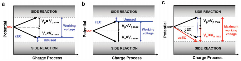
Mechanistically, cEC achieves the energy storage by anion and cation adsorption on the surface of positive and negative electrodes, respectively. During the charging process, the potential changes for positive and negative electrodes are synchronal, as shown in Fig. 1, and there are upper and lower limit for both electrodes (Figs. 1a and b). For cECs, electrochemical stable stands for no side reaction occurred. And the maximum electrochemical stable voltage of commercial non-aqueous carbon-based EDLCs is commonly 2.7 V [26, 27]. When EDLCs are charged/discharged within electrochemical stable potential window, there is rarely side reaction occurred at electrode, and the coulombic efficiency is approximately 100%. Once the potential of any electrode breaks the limit, the multiple types of side reaction on positive or negative electrode occurs [28], which both leads to poor coulombic efficiency and low cycle life. Unfortunately, the distinct properties of the cation and anion in electrolyte, for instance, size, charge, and solvation properties, yields to an asymmetry in the charging processes on the positive and negative electrodes [3], which means the potential windows of positive and negative electrodes for charging are probably asymmetrical as shown in Figs. 1a and b. Therefore, the voltage of cEC should be controlled by the stable upper and lower potentials simultaneously, and more often than not only one electrode reaches the maximum potential, i.e., the stable working voltage of current cEC has not been fully used [1, 29]. The idea of unbalanced structure was only occasionally reported in the literature for aqueous supercapacitors [25].

|
Download:
|
| Fig. 1. The scheme images of charge profiles for carbon-based electrochemical capacitors. Balanced electrochemical capacitor with unused lower voltage range (a), unused higher voltage range (b), and unbalanced electrochemical capacitor with fully used safe working voltage (c). | |
Herein, we proposed to construct an unbalanced non-aqueous carbon-based electrochemical capacitor (ucEC) to make full use of stable working voltage range for improving energy density as shown in Fig. 1c. By optimizing the weight ratio of positive electrode to negative electrode, we are able to fully utlize the voltage range so that both positive and negative electrodes reach the maximum potential for stable cycling [30, 31] (Section S1 in Supporting information). As a result, ucEC with adjusted mass ratio of electrode can operate at higher working voltage, which enables to largely enhance the energy density. Moreover, decreasing the mass loading of one electrode can decrease the weight of device, which would cut manufacturing costs and further enhance the energy density. Specifically, the ucEC delivers an improved energy density up to 64.9 Wh/kg (1.4 times as high as a general cEC) without sacrificing the power density and cycle life. This simple and general approach possesses a great potential for improving the energy density of electrochemical capacitors at minimum engineering cost.
N2 adsorption-desorption isotherm of the activated carbon (AC) was ascribed to typical type Ⅰ isotherms according to IUPAC classification. And the morphologies and microstructure were observed through field emission scanning electron microscopy (SEM, Zeiss Ultra 55) at 5 kV, JEOL 1010 transmission electron microscope (TEM), and FEI Tecnai 20 high-resolution (HRTEM). Electrodes were prepared by doctor-blade coating method [32]. The slurry composed of AC (90 wt%, Kuraray YP-50F), Ketjen Black (5 wt%) and PVDF (5 wt%) was coated on aluminum foil. After drying in air at 80 ℃ for 24 h, the electrodes were obtained by punching the foil into small piece with a dimeter of 12.0 mm. The coin cells (CR2032) were fabricated in an Ar filled glove box, with a microporous glass microfiber filter (Whatman GF/F) as separator and electrolyte composed of 1 mol/L tetraethylammonium tetrafluoroborate (TEATFB) in propylene carbonate (PC). Electrode mass ratios of tested capacitors are summarized as shown in Table S1 (Supporting information).
The cyclic voltammetry (CV) profiles at different voltage ranges and scanning rates were recorded using CHI660. The electrochemical impedance spectroscopy (EIS) was tested at the open circuit voltage (OCV) within the frequency of 10-1–106 Hz using CHI660. The galvanostatic charge and discharge tests were conducted using a Neware battery tester.
The specific capacitance (C), energy density (E) and power density (P) of electrochemical capacitors are calculated using Eqs. (1)–(3) [33, 34], where I is the constant current density based on total mass of positive and negative electrode, Δt is the discharge time, and V is the working voltage.

|
(1) |

|
(2) |

|
(3) |
As the porosities of AC shown in Fig. S1 (Supporting information), indicating there are mainly micropores and mesopores in AC, and the specific surface area is as high as 1600 cm3/g. There is no obvious pore over 50 nm could be observed, as revealed in the TEM images (Figs. S1c and d), indicating no macroporous existing in AC.
We firstly explored the stable voltage range of various ucEC systems (abbreviated to ucEC-X:Y) using CV at the scanning rate of 10 mV/s, where X:Y represents the mass ratio of negative electrode to positive electrode. The CV tests of different mass ratios of ucEC and cEC at a voltage of 2.7 V were compared in Fig. 2a. All curves are shown typical rectangular shape, indicating double-layer electrochemical properties [35]. However, the ucECs with less negative electrode mass ratio (X < Y) have more rectangular shape than cEC, but the situations of the ucECs with less positive electrode mass ratio (X > Y) is contrary. It is indicated by adjusting the mass ratio of electrodes, the influence of side reactions can be mitigated. As shown in Fig. 2b, the CV curves are rectangular shape under different voltage ranges, illustrating the total double-layer electrochemical properties of these ucEC systems [35]. If the cell voltage range is increased beyond 2.7 V, a current increase can be noticed at high voltage range (Fig. 2b and Fig. S2 in Supporting information). The current-increase tail indicates the unwanted decomposition of electrolyte, which is a faradic process [25, 36]. The existence of tail decreases the calculated capacitance ratio of anodic and cathodic processes (A/C ratio, the calculation formula is shown in Section S2 in Supporting information). As A/C ratio shown in Figs. 2c and d and Fig. S3 (Supporting information), the results are less than 100%. The reason is that the porous surface of electrode would contain various impurities and functional groups, which would involve Faradic charge transfer in the potential range of operations. These kinds of Faradic reactions can be considered as self-discharge reaction, which will decrease the total amount of charges in the double-layer [37, 38]. With increasing the operating voltage range, the A/C ratio decreases gradually, which indicates some side reactions occurred on positive electrode and/or negative electrode [35]. As shown in Fig. S3, when the weight of negative electrode is higher than positive electrode, i.e., X > Y, the A/C ratio decreases continuously with the X increasing, indicating that positive electrode reaches the potential limit for safe operation first (Fig. 1a). On the contrary, when X < Y, i.e., the weight of negative electrode is lower than positive electrode, an highest A/C ratio is obtained when the X:Y = 1:1.3 (Figs. 2c and d), indicating there exists unused voltage range for negative electrode (Fig. 1a). These results confirm the stable voltage window of cEC is in accord with the Fig. 1a, which indicates we can construct ucEC by reducing the weight of negative electrode to enlarge the working voltage range (Fig. 1c), and the stable voltage window would be fully utilized when the weight ratio of negative electrode to positive electrode was optimized to 1:1.3.

|
Download:
|
| Fig. 2. (a) The CV curves of various ucEC within the voltage range of 0–2.7 V at the scanning rate of 10 mV/s; (b) The CV curves of cEC within different voltage ranges from 0–2.1 to 0–3.5 V; (c, d) The coulombic efficiency of various ucEC within various voltage ranges; (e) Multi-rate performance of cEC-1:1 and ucEC-1:1.3 at different current densities; (f) The charge and discharge profiles of ucEC-1:1.3@96% at different current densities; (g) The cycling performance of cEC-1:1 and ucEC-1:1.3; (h) Ragone-plot of cEC-1:1 and ucEC-1:1.3. | |
Based on the above analysis, we comprehensively evaluated electrochemical performance of two specific structures of cEC-1:1 and ucEC-1:1.3 with the A/C ratios of 98% and 96%, which could represent the situations with no side reactions and minor side reactions respectively due to unstable working voltage range. It needs to be noted that all the A/C ratios are lower than 100%, which is probably resulted from the side reactions of functional groups and electrolyte [28]. As expectedly, the working voltages for ucEC-1:1.3 are 2.68 V (ucEC-1:1.3@98%) and 3.20 V (ucEC-1:1.3@96%), much higher than those for cEC-1:1.3, i.e., 2.38 V (cEC-1:1@98%) and 2.93 V (cEC-1:1@96%), which are obtained from Fig. 2d and Table S2 (Supporting information). Therefore, the multi-rate performance and cycle stability of cEC-1:1 and ucEC-1:1.3 were conducted under their corresponding working voltages as shown in Figs. 2e–h. At the low current density of 0.1 A/g, ucEC-1:1.3 delivers a higher specific capacitance of 12.60 F/gtotal (@96%) and 15.16 F/gtotal (@98%), respectively, in comparison with those of cEC-1:1, which are 12.16 F/gtotal (@96%) and 14.23 F/gtotal (@98%), respectively, as shown in Fig. 2e, Figs. S4 and S5 (Supporting information). After carefully comparing the charge and discharge processes of cEC-1:1 and ucEC-1:1.3 (Section S3 in Supporting information), it can be speculated that the enhancement of specific capacitance is due to the reduced electrode weight and the ucEC structure would lower the potential of positive electrode and mitigate the side reactions on positive electrode. Meanwhile, the above obtained A/C ratios of ucEC areclarified tobe caused bythe side reactions of both positive and negative electrodes. At low current densities, ucEC-1:1.3 delivers similar synchronous degradation rate with cEC-1:1. However, surprisinglyucEC-1:1.3 exhibits much higher capacitance retentions than cEC-1:1 when the current densities increased to higher than 4 A/g. This result indicates the side-reaction original from positive electrode might cause more severe effect than negative electrodefor multi-rate performance [28], which will also be further investigated later in this section. Also, initial coulombic efficiency is less than 100%, and at 50 times, there is a significant change. This phenomenon is resulted from the side Faradic reactions on the surface during first several cycle due to the redox reaction of impurities and functional groups on the carbon surface [39, 40]. Moreover, after long cycles testing, the impurities and surface functional groups would be consumed. Hence, when the capacitors are charged/discharged again under low current density, the coulombic efficiency is near 100%.
Furthermore, long-term cycling performance was performed at the currentdensityof 2 A/g for10, 000cycles, as shown in Fig. 2g and Fig. S6 (Supporting information).Consistentwith theresultsinFig.2e, the ucEC-1:1.3 exhibits higher initial capacitance of 20.26F/g@98%, and 21.75F/g@96%thancEC-1:1(18.53F/g@98%, and19.70F/g@96%), and similar capacitance retentions after 10, 000 cycles of 90.4% (@98%), 77.3% (@96%) for ucEC-1:1.3, and 93.1% (@98%), 77.4% (@96%) for cEC-1:1, respectively. Ragone Plot graph (Fig. 2h) displays that ucEC-1:1.3 delivers improved energy density of 38.8Wh/kg (@98%) and 45.8Wh/kg (@96%) and power density of (2.6kW/kg (@98%) and 2.8kW/kg (@96%)) in comparison with cEC-1:1. These results confirm constructing unbalanced structure is effective to expand the working voltage and thus improved energy density and power density. Moreover, the ucEC still kept excellent long-term cycling performance, exhibiting a great potential for practical applications.
To carefully illustrate the electrode stability in ucEC-1:1.3 structures, EIS was utilized to characterize the electrodes after 10, 000 cycles by constructing new capacitors consisted of a fresh AC electrode and a cycled AC electrode (Section S4 in Supporting information), which enables the separate analysis of cycled positive and negative electrodes [41, 42]. In general, the energy storage process for cEC is a non-faradic process. Ideal EIS curves should be consisted of three regions, including a pure resistance at very high frequency, a vertical line representing a pure capacitive behavior at very low frequency, and the influence of electrode porosity in the middle frequency domain [13, 43, 44]. However, the actual curves also include a semi-circle, which is suggested to represent interfacial impedance between active material/current collector and between active material/ active material [45, 46]. The overall resistance of semi-circle is raised through formation of faradic side-reaction products on the active material [46]. Moreover, the slope of the inclined linear line of actual capacitor is no longer 90° and the deviation degrees acts as an indicator for non-ideality (faradic side-reactions) of the capacitive behavior [46-48]. Figs. 3a and b display the EIS curves of positive and negative electrodes after cycling, respectively, and corresponding deviation degrees are summarized in Fig. 3c. The positive electrodes at 96% conditions have larger deviation in comparison with thesamples at 98%, which indicatesmore side-reaction at96% conditions. And the cEC-1:1 shows a more serious deviation than ucEC-1:1.3 for positive electrode, indicating the positive electrode of cEC-1:1 reached higher potential than the positive electrode of ucEC-1:1.3, resulting in severer side-reaction. On the other hand, only the ucEC-1:1.3@96% negative electrode reveals obvious deviation, indicating side-reaction only occurs in this case. The charging potentials of positive and negative electrodes for these samples can be summarized as shown in Fig. 3d and Table S3 (Supporting information). The A/C ratio for ucEC-1:1.3@96% is affected by combined reaction of positive and negative electrodes, and the unbalanced structure mitigates the side-reactions on positive electrode, consistent with the electrochemistry results above.

|
Download:
|
| Fig. 3. (a, b) EIS curves of positive and negative electrodes after cycling, respectively; (c) Corresponding charge transfer deviation degrees of EIS curves; (d) Schematic of electrode potentials for positive and negative electrodes. | |
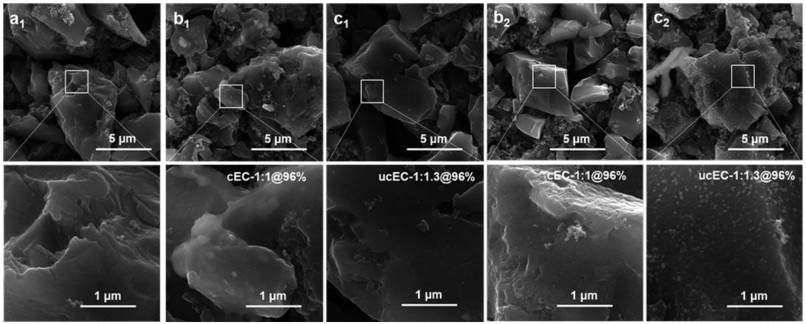
Furthermore, the SEM of fresh and cycled electrodes was also performed as shown in Fig. 4 and Fig. S7 (Supporting information). At the 98% conditions, there are no obvious morphological changes in comparison with fresh electrode regardless of positive and negative electrodes (Fig. S7), indicating the working potentials for positive or negative electrodes are all in stable voltage range with no serious side-reaction. However, when the A/C ratio decreases to 96%, the morphology of positive and negative electrodes for cEC-1:1 and ucEC-1:1.3 are quite different. It can be clearly observed that a layer of polymeric products (indicative of SEI formation) on positive electrode of cEC-1:1 and on negative electrode of ucEC-1:1.3 (Figs. 4b and c), which suggests the positive electrode of cEC-1:1 reaches a higher potential than ucEC-1:1.3, while the negative electrode of ucEC-1:1.3 operates at lower potential. Therefore, the SEM results also demonstrate the electrode behaviors of positive and negative electrode in consistent with the result in Fig. 3d.

|
Download:
|
| Fig. 4. SEM images of fresh electrodes (a), cEC-1:1@96% electrodes (b) and ucEC-1:1.3@96% electrodes (c); (X1) represents the images of positive electrode; (X2) represents the images of negative electrode. | |
In this study, an unbalanced carbon-based electrochemical capacitor is constructed by adjusting the negative and positive electrode ratio to an optimal value of 1:1.3. The unbalanced structure enables the electrochemical capacitor to fully utilize the stable working voltage of 2.68 V with 98% columbic efficiency and 3.20 V with 96% coulombic efficiency. As a result, the ucEC is capable to deliver a higher energy density of 64.9 Wh/kg, 1.4 times higher than that for cEC. Most importantly, the ucEC keeps an ultrahigh power density of 10.3 kW/kg and ultra-stable long-term cycling life of 74.5% capacitance retention after 10, 000 cycles. The electrochemical stability of the ucEC are also comprehensively illustrated by EIS and SEM of cycled electrodes., The reported ucEC provides a feasible approach to improve the energy density without sacrificing the power density and cycle life for practical applications.
Declaration of competing interestThe authors declare that they have no known competing financial interests or personal relationships that could have appeared to influence the work reported in this paper.
AcknowledgmentsThe authors acknowledge the financial support from the National Natural Science Foundation of China (No. 51777140) and the Fundamental Research Funds for the Central Universities at Tongji University (No. 22120180519/22120180308). Also, this work was partly supported by US Army Research Laboratory (No. W911NF-12-R-0011-03).
Appendix A. Supplementary dataSupplementary material related to this article can be found, inthe online version, at doi:https://doi.org/10.1016/j.cclet.2019.09.048.
| [1] |
N.S. Choi, Z. Chen, S.A. Freunberger, et al., Angew. Chem. Int. Ed. 51 (2012) 9994-10024. DOI:10.1002/anie.201201429 |
| [2] |
R.R. Salunkhe, Y.H. Lee, K.H. Chang, et al., Chemistry 20 (2014) 13838-13852. DOI:10.1002/chem.201403649 |
| [3] |
Y. Zhai, Y. Dou, D. Zhao, et al., Adv. Mater. 23 (2011) 4828-4850. DOI:10.1002/adma.201100984 |
| [4] |
B. Li, J. Zheng, H. Zhang, et al., Adv. Mater. (2018) 1705670. |
| [5] |
F. Beguin, V. Presser, A. Balducci, E. Frackowiak, Adv. Mater. 26 (2014) 2219-2251, 2283. DOI:10.1002/adma.201304137 |
| [6] |
L. Jin, R. Gong, W. Zhang, et al., J. Mater. Chem. A 7 (2019) 8234-8244. DOI:10.1039/C8TA12000E |
| [7] |
H. Zhao, L. Liu, R. Vellacheri, Y. Lei, Adv. Sci. 4 (2017) 1700188. DOI:10.1002/advs.201700188 |
| [8] |
J. Chmiola, G. Yushin, Y. Gogotsi, et al., Science 313 (2006) 1760-1763. DOI:10.1126/science.1132195 |
| [9] |
J. Fang, X. Miao, X. Zhang, et al., J. Power Sources 418 (2019) 24-32. DOI:10.1016/j.jpowsour.2019.01.076 |
| [10] |
S. Kulandaivalu, Y. Sulaiman, J. Power Sources 419 (2019) 181-191. DOI:10.1016/j.jpowsour.2019.02.079 |
| [11] |
M.M. Hantel, T. Kaspar, R. Nesper, et al., Electrochem. Commun. 13 (2011) 90-92. DOI:10.1016/j.elecom.2010.11.021 |
| [12] |
G. Wang, J. Zhang, S. Kuang, et al., Electrochim. Acta 153 (2015) 273-279. DOI:10.1016/j.electacta.2014.12.006 |
| [13] |
Y.R. Nian, H. Teng, J. Electroanal. Chem. 540 (2003) 119-127. DOI:10.1016/S0022-0728(02)01299-8 |
| [14] |
Y. Gu, L.Q. Fan, J.L. Huang, et al., J. Power Sources 425 (2019) 60-68. DOI:10.1016/j.jpowsour.2019.03.123 |
| [15] |
D. Zhao, H. Liu, X. Wu, Nano Energy 57 (2019) 363-370. DOI:10.1016/j.nanoen.2018.12.066 |
| [16] |
Y. Liu, D. Zhao, H. Liu, et al., Chin. Chem. Lett. 30 (2019) 1105-1110. DOI:10.1016/j.cclet.2018.12.024 |
| [17] |
L. Demarconnay, E. Raymundo-Piñero, F. Béguin, J. Power Sources 196 (2011) 580-586. DOI:10.1016/j.jpowsour.2010.06.013 |
| [18] |
R. Na, C.W. Su, Y.H. Su, et al., J. Mater. Chem. A 5 (2017) 19703-19713. DOI:10.1039/C7TA05358D |
| [19] |
H.C. Huang, Y.C. Yen, J.C. Chang, et al., J. Mater. Chem. A 4 (2016) 19160-19169. DOI:10.1039/C6TA08203C |
| [20] |
L. Jin, X. Guo, R. Gong, et al., Energy Storage Mater. 23 (2019) 409-417. DOI:10.1016/j.ensm.2019.04.027 |
| [21] |
J.P. Zheng, J. Huang, T.R. Jow, J. Electrochem. Soc. 144 (1997) 2026-2031. DOI:10.1149/1.1837738 |
| [22] |
J.P. Zheng, T.R. Jow, J. Electrochem. Soc. 144 (1997) 2417-2420. DOI:10.1149/1.1837829 |
| [23] |
K. Naoi, S. Ishimoto, J. Miyamoto, W. Naoi, Energy Environ. Sci. 5 (2012) 9363. DOI:10.1039/c2ee21675b |
| [24] |
M. Yu, D. Lin, H. Feng, et al., Angew. Chem. Int. Ed. 56 (2017) 5454-5459. DOI:10.1002/anie.201701737 |
| [25] |
J.H. Chae, G.Z. Chen, Electrochim. Acta 86 (2012) 248-254. DOI:10.1016/j.electacta.2012.07.033 |
| [26] |
M. Hahn, A. Würsig, R. Gallay, et al., Electrochem. Commun. 7 (2005) 925-930. DOI:10.1016/j.elecom.2005.06.015 |
| [27] |
M. Hahn, O. Barbieri, F.P. Campana, et al., Appl. Phys. A 82 (2006) 633-638. |
| [28] |
S. Ishimoto, Y. Asakawa, M. Shinya, K. Naoi, J.Electrochem. Soc. 156 (2009) A563. DOI:10.1149/1.3126423 |
| [29] |
D. Cericola, R. Kötz, A. Wokaun, J. Power Sources 196 (2011) 3114-3118. DOI:10.1016/j.jpowsour.2010.11.157 |
| [30] |
D. Zhao, X. Wu, C. Guo, Inorg. Chem. Front. 5 (2018) 1378-1385. DOI:10.1039/C8QI00170G |
| [31] |
H. Liu, D. Zhao, Y. Liu, et al., Chem. Eng. J. 373 (2019) 485-492. DOI:10.1016/j.cej.2019.05.066 |
| [32] |
L. Jin, R. Gong, J. Zheng, et al., ChemElectroChem 6 (2019) 3020-3029. DOI:10.1002/celc.201900169 |
| [33] |
D. Zhao, M. Dai, H. Liu, et al., Cryst. Growth Des. 19 (2019) 1921-1929. DOI:10.1021/acs.cgd.8b01904 |
| [34] |
H. Liu, D. Zhao, P. Hu, X. Wu, Chin. Chem. Lett. 29 (2018) 1799-1803. DOI:10.1016/j.cclet.2018.11.019 |
| [35] |
A. Lewandowski, A. Olejniczak, M. Galinski, I. Stepniak, J. Power Sources 195 (2010) 5814-5819. DOI:10.1016/j.jpowsour.2010.03.082 |
| [36] |
V. Khomenko, E. Raymundo-Piñero, E. Frackowiak, F. Béguin, Appl. Phys. A:Mater. Sci. Process. 82 (2006) 567-573. DOI:10.1007/s00339-005-3397-8 |
| [37] |
B.E. Conway, W.G. Pell, T.C. Liu, J. Power Sources 65 (1997) 53-59. DOI:10.1016/S0378-7753(97)02468-3 |
| [38] |
D. Qu, J. Power Sources 109 (2002) 403-411. DOI:10.1016/S0378-7753(02)00108-8 |
| [39] |
D. Qu, H. Shi, J. Power Sources 74 (1998) 99-107. DOI:10.1016/S0378-7753(98)00038-X |
| [40] |
M. He, K. Fic, E. Fraçkowiak, et al., Energy Storage Mater. 5 (2016) 111-115. DOI:10.1016/j.ensm.2016.06.001 |
| [41] |
W.J. Cao, J.F. Luo, J. Yan, et al., J. Electrochem. Soc. 164 (2017) A93-A98. DOI:10.1149/2.0351702jes |
| [42] |
W.J. Cao, J.P. Zheng, J. Power Sources 213 (2012) 180-185. DOI:10.1016/j.jpowsour.2012.04.033 |
| [43] |
J.S. Zheng, L. Zhang, A. Shellikeri, et al., Sci. Rep. 7 (2017) 41910. DOI:10.1038/srep41910 |
| [44] |
L. Jin, J. Zheng, Q. Wu, et al., Mater. Today Energy 7 (2018) 51-57. DOI:10.1016/j.mtener.2017.12.003 |
| [45] |
C. Portet, P.L. Taberna, P. Simon, C. Laberty-Robert, Electrochim. Acta 49 (2004) 905-912. DOI:10.1016/j.electacta.2003.09.043 |
| [46] |
Y.-R. Nian, H. Teng, J. Electroanal. Chem. 540 (2003) 119-127. DOI:10.1016/S0022-0728(02)01299-8 |
| [47] |
W.J. Cao, J.P. Zheng, J. Electrochem. Soc. 160 (2013) A1572-A1576. DOI:10.1149/2.114309jes |
| [48] |
W. Cao, J. Zheng, D. Adams, et al., J. Electrochem. Soc. 161 (2014) A2087-A2092. DOI:10.1149/2.0431414jes |