 2020, Vol. 31


b Key Laboratory of Low-grade Energy Utilization Technologies and Systems, Chongqing University, Chongqing 400044, China;
c College of Materials Science and Engineering, Shenzhen University, Shenzhen 518055, China;
d Department of Electronics Engineering, The Chinese University of Hong Kong, Hong Kong, China
Hydrogen (H2), as a clean and renewable energy carrier, is a critical strategy to overcome energy demands and oil resource exhausting [1-3]. An electrochemical process such as water splitting has been widely investigated for conversion of electrical energy into fuels. Water reduction or hydrogen evolution reactions (HER) is one of the most promising ways to produce hydrogen. However, it is a thermodynamically uphill reaction and thus needs external energies such as electricity to promote the reaction. Thus far, the precious metals are the state-of-the-art catalysts (such as Pt, Pd and Ir) to promote electrocatalytic hydrogen and oxygen generation [4]. Furthermore, the advanced Ir-based phosphide has been showed high performance for HER and further to decrease noble metal dosage at the same time [5]. However, their high cost and scarcity pose great constraints for commercialization and feasibility on a larger scale [6].
As is known, enormous efforts have been made to develop cost-efficient alternatives including sulphides, phosphides, and transition metal compounds [7-15]. Among various HER electro-catalysts, transition-metal phosphides in particular, such as Ni2P [16-18], CoP [19-22], MoP [23] and Cu3P [24] nanomaterials, have attracted great attention owing to their hydrogenase-like catalytic mechanism and also due to the versatility of P in regulating the electronic structure [25-28]. Nevertheless, one anionic active site could be generated from the transformation of the valence electrons, leading to a less efficient proton discharge process. Meanwhile, transition metals could result in redistributions of the valence electrons, which can lead to an increase of HER activity [29-31]. Unfortunately, these compound electrocatalysts usually suffered from low electrical conductivity limited surface area and slow diffusion of electrolyte [32]. Adding insult to injury, the electrocatalysts also easily agglomerate, resulting in poor long-term stability and limited surface area.
Considering the dispersity and electrical conductivity of materials play great roles in their electrocatalytic performances, the 3D hierarchically porous Ni may be an effective method, which could afford more electrocatalysts and serve as a binder-free substrate for better electrocatalytic performance. Here, we fabricate porous Ni film efficient current collectors to support NiCoP 1D nanothorn electroactive materials. The porous Ni/NiCoP integrated electrodes exhibit excellent electrocatalytic activity toward HER with exceptional overpotentials of 61 mV at a current density of 10 mA/cm2 and small Tafel slopes of 75 mV/dec in alkaline solution. The long-term stability of the porous Ni/NiCoP integrated electrodes is also very remarkable during the HER. The high electrochemical performance might be resulted from the composite integrated electrode with large surface area, lots of active sites, and short diffusion lengths for the transport of both active species and charges (ions and electrons).
NiCoP nanothorns grown on porous Ni can be fabricated via three steps. At first, the porous structures on the Ni foils were electrodeposited at a constant current of 2.5 A for 60 s by a common DC power supply with the solution containing 0.1 mol/L NiCl2 and 2 mol/L NH4Cl. Then, the above 3 D porous Ni foil and the solution including NiCl2·6H2O (1 mmol), CoCl2·6H2O (2 mmol) and urea (3 mmol) were transferred into a 100 mL Teflon-lined stainless-steel autoclave, keeping the autoclave at 120 ℃ for 6 h. Finally, all of these precursors were placed at the middle of a tube furnace, and 1.0 g NaH2PO2·H2O was placed at the upstream side. The temperature of the furnace was elevated to 300 ℃ for 2 h with a ramping rate of 2 ℃/min in Ar atmosphere. For comparison, NiCoP nanothorns grown on smooth Ni foil (Ni foil/NiCoP) and commercial Ni foam (Ni foam/NiCoP) were prepared by the same method.
All the electrochemical tests were conducted on an electro-chemical station (Zennium, Zahner, Germany) under a three-electrode cell configuration at room temperature in 1 mol/L KOH. The Ni/NiCoP was used as working electrode and the loading amount of NiCoP was ~1.5 mg/cm2, with a graphite rod and Ag/ AgCl as the counter and reference electrodes, respectively. The potentials vs Ag/AgCl were converted to the reversible hydrogen electrode (RHE) using the relationship:
|
(1) |
where E(Ag/AgCl vs. NHE) is 0.222 V at 25 ℃.
All the data reported in this work were corrected for IR loss and given versus reversible hydrogen electrode (RHE). The cyclic voltammetry (CV), linear sweep voltammetry (LSV), cycling performance, electrochemical impedance spectroscopy (EIS), chronoamperometry and chronopotentiometry were tested by an electrochemical station. Before electrochemical test, the working electrodes were activated at 100 mV/s for 100 cycles.
Field-emission scanning electron microscopy (FEI Nova Nano SEM 450) and high-resolution transmission electron microscopy (HRTEM, Tecnai G2F20 FEI) were employed to investigate the morphologies and structures. The crystallographic information was characterized by X-ray diffraction (XRD, Rigaku D/Max2500, Japan). The surface element composition was confirmed by X-ray photoelectron spectra spectrometer (XPS, PHI-1800, Japan) using the C 1s level at 284.4 eV.
SEM images in Figs. 1a-c show that the typical 3D porous Ni films are made of numerous nanoparticles, which connected each other with abundant interlaced bridging branches. During the electrodeposition process, the generation of hydrogen gas and metal Ni could result in interconnected pores. Thus, the hydrogen bubbles play a significant role in depositing mechanically self-supported 3D porous Ni films. Compared with the commercial Ni foam with large pores (Fig. S1 in Supporting information), the hierarchically porous Ni films own abundant micro-nano pathways to accelerate electron transportation and electrolyte penetration. A closer examination reveals that NiCoP nanothorns are vertically aligned on the substrate (Figs. 1d-f). The radially standing 1D nanothorns are about 70 nm in diameter and about 7 μm in length.

|
Download:
|
| Fig. 1. SEM images of (a–c) 3D porous Ni skeletons, and (d–f) porous Ni/NiCoP at diff; erent magnifications. | |
NiCoP active materials also display clear 1D thorn-like structural features in the TEM images (Fig. 2a). A well-resolved fringe is observed in the high-resolution TEM (HRTEM) (Fig. 2b). The core has clear lattice fringes with inter-planar spacing of 0.220 nm and 0.168 nm, corresponding to the (111) plane and (300) plane of NiCoP, respectively [33]. The corresponding fast Fourier transform (FFT) images (inset) recorded for NiCoP show the hexagonal structure of the single crystal, which confirms the homogeneous distribution of the three elements. The energy dispersive X-ray spectroscopy (EDS) elemental mapping images (Fig. 2c) further reflect the homogeneous distribution of the Ni, Co and P elements, indicating a uniform transformation of the Ni-Co precursor into NiCoP nanothorns. X-ray diffraction (XRD) pattern results (Fig. 2d) suggest that the NiCo precursor is successfully converted into hexagonal NiCoP through the phosphorization reaction. The most obvious peaks at 44.4°, 51.7° and 76.4° from the Ni substrate (JCPDS No. 04-0850), and all the other peaks could be found from NiCoP (JCPDS No. 71-2336) and NiCo2O4 (JCPDS card No. 20-0781), respectively.

|
Download:
|
| Fig. 2. (a) TEM image. (b) HR-TEM image. The inset in (b) shows the corresponding FFT pattern. (c) TEM image and the corresponding EDX mapping for Ni, Co, and P elements of NiCoP. (d) XRD patterns of porous Ni, porous Ni/NiCo2O4 and porous Ni/NiCoP. | |
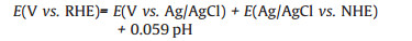
XPS measurements are conducted to probe the surface chemistry of NiCoP. The full XPS spectrum (Fig. 3a) presents the multiple splitting peaks for the Ni 2p, Co 2p and P 2p regions. The Ni 2p3/2 core level spectrum (Fig. 3b) shows three main peaks at binding energies of 853.3 eV, 856.8 eV and 861.9 eV, which should be related to the Ni-P, Ni POx, and the satellite peak, respectively [34]. Similarly, the Co 2p3/2 spectrum (Fig. 3c) possesses a new peak located at 780.4 eV assigned to oxidized metal phosphate [35]. The energy is slightly higher than that of metallic Co (778.2 eV) [36], indicating that the Co carries a partially positive charge. The peak at 795.4 eV could be associated with Co-POx. The P 2p region (Fig. 3d) is deconvoluted into two main peaks centered at 129.4 eV and 134.3 eV, assigned to reduced phosphorus and phosphate species (P5+) [37]. The binding energy of 129.4 eV is slightly lower than that of elemental P (130.0 eV) [38], which reveals the increased electron occupation, resulting in enhanced electron-donating ability. During the electrocatalysis process, NiCoP has a moderate interaction with hydrogen species. The proton-acceptor sites (the negative P centers) strongly trap the protons and the hydride-acceptor sites (the positive Ni and Co centers) afford moderate bonding to the hydrogen, which work in a collaborative way [39]. Electrons diffuse from metallic sites Ni and Co to P, which helps accelerate the adsorption and desorption process [40].

|
Download:
|
| Fig. 3. (a) XPS full spectrum of NiCoP, and the deconvoluted Ni 2p (b), Co 2p (c) and P 2p (d) XPS spectra of NiCoP. | |
The hydrogen evolution activity of the nickel-based electrode is measured by an electrochemical workstation in an alkaline electrolyte of 1.0 mol/L KOH. The polarization curve after IR correction is shown in Fig. 4a. It can be observed that the overpotential of porous Ni/NiCoP, Ni foam/NiCoP, Ni foil/NiCoP, porous Ni/NiCo2O4 and porous Ni electrode is 61 mV, 151 mV, 189 mV, 257 mV and 318 mV, respectively, when the current density is 10 mA/cm2 (Fig. 4b). The results indicate the electrocatalytic active order for HER from high to low: Porous Ni/NiCoP, Ni foam/NiCoP, Ni foil/NiCoP, porous Ni/NiCo2O4 and porous Ni electrode. It could be seen in Fig. S1 that as-prepared porous Ni films demonstrate much highly porous than the commercial Ni foam. Thus, the NiCoP nanothorns grown on the porous Ni films could provide more active sites for HER electro-catalysis relative to the NiCoP nanothorns grown on the commer-cial Ni foams. The results also indicate that the NiCoP possess much highly active than the NiCo2O4 for HER electrolysis. The outstand-ing HER performance of NiCoP owes to the advantageous structure and chemical composition that could improve electrical conduc-tivity and electron transport [41]. More specifically, the incorpo-ration of metal atoms into binary metal phosphides promote synergistic effect between Ni and Co, which may manipulate their electronic structure and tune the hydrogen adsorption energy at the same time [42].

|
Download:
|
| Fig. 4. HER electrocatalysis in 1 mol/L KOH. (a) The porous Ni/NiCoP recorded at a scan rate of 5 mV/s, along with porous Ni, Ni foam/NiCoP, Ni foil/NiCoP and porous Ni/ NiCo2O4 for comparison. (b) Polarization curves-derived Tafel slopes. (c) Overpotential at 10 mA/cm2 of various as-prepared samples. (d) The comparative Nyquist plots of electrochemical impedance spectra. The inset enlarged plots. | |
The catalysis kinetics for HER performance of the NiCoP could be further examined by a standard three-electrode cell in 1 mol/L KOH. The linear portions of the Tafel plots are fitted to the Tafel equation (η = blog|j| + a, where j is the current density and b is the Tafel slope), The Tafel slopes obtained in linear portions of the relevant polarization curves are 75, 240 and 310 mV/dec for the porous Ni/NiCoP, Ni foam/NiCoP and Ni foil/NiCoP, respectively (Fig. 4c). The lowest overpotential and smallest Tafel slope show the superior of the porous Ni/NiCoP, which is among the recently reported nonprecious metal catalysts as shown in Table S1 (Supporting information). More specifically, overpotential or Tafel slope of the porous Ni/NiCoP is smaller than those of NiCoP/CNF (130 mV, 83 mV/dec) [43], NiFe LDH@NiCoP (120 mV, 88.2 mV/dec) [44], Co2P@NPG (165 mV, 96 mV/dec) [45], NiCoP/rGO (209 mV, 124 mV/dec) [46] and NiCoP/Ni Foam (133 mV, 68.6 mV/ dec) [47], indicating the HER proceeds by a Volmer-Heyrovsky mechanism [48]. EIS method is performed to investigate the HER kinetic of the porous Ni/NiCoP at electrode/electrolyte interface (Fig. 4d). In general, smaller slope value means more available electrochemical reaction kinetics, the porous Ni/NiCoP shows much smaller semicircle than Ni foli/NiCoP and Ni foam/NiCoP. This result also might explain the best electrocatalytic properties of the porous Ni/NiCoP for HER [49].
We further test the stability of the porous Ni/NiCoP by a chronoamperometric method. It is worth noting that the porus Ni/ NiCoP electrodes exhibit superior activity compared with the Ni foil/NiCoP electrodes toward HER at 20 mA/cm2 for 20 h in 1 mol/L KOH solution as shown in Fig. S2a (Supporting information). As shown in Fig. S2b (Supporting information), amperometry is performed at the overpotential of 100 mV. The current density of porous Ni/NiCoP mostly retains during the continuous hydrogen-release for 200 h. Meanwhile, the stability is firstly accessed by cyclic voltammetry via cycling 1000 times at a scan rate of 100 mV/ s. The LSV curve of the porous Ni/NiCoP after 1000 cycling is nearly unchanged compared with the initial one. The results also confirm the remarkable stability of porous Ni/NiCoP electrodes. The 1D NiCoP nanothorns directly grown on the highly porous Ni films could avoid the agglomeration of the nanomaterials and improve the adhesion with the porous Ni substrates, resulting the enhancement of stability. For simplicity and practical application, we manufacture a device with a commercial Si solar cell (5 W, 5 V, 1 A) for a high-current test using sunlight in Fig. S3 (Supporting information). The device can work normally for a long time, which gives us a strategy for self-powered hydrogen generation.
In summary, integrated electrodes of 3D porous Ni films supported NiCoP nanothorns are prepared by successive electro-deposition, hydrothermal and phosphatized process. The superior catalytic performance of the porous Ni/NiCoP electrodes might be ascribed to the unique architecture of nanothorn active materials which could expose more catalytic active sites, the fast mass transport and charge transfer as well as the synergistic effect of bimetallic NiCo phosphides which would improve the conductivity and intrinsic catalytic activity. The integrated solar-driven system provides an opportunity to use the vast seawater on the Earth as an energy carrier.
AcknowledgmentsThis work was supported by the National Natural Science Foundation of China (No. 21203236), Guangdong Department of Science and Technology (No. 2017A050501052), Guangdong Provincial Key Laboratory (No. 2014B030301014) and Shenzhen Research Plan (No. JCYJ20160229195455154).
Appendix A. Supplementary dataSupplementary material related to this article can be found, in the online version, at doi:https://doi.org/10.1016/j.cclet.2019.06.021.
| [1] |
H. Fei, J. Dong, M. Josefina Arellano-Jiménez, et al., Nat. Commun. 6 (2015) 8668. DOI:10.1038/ncomms9668 |
| [2] |
Z.H. Pu, Y. Xue, W.Q. Li, I.S. Amiinu, S.C. Mu, New J. Chem. 41 (2017) 2154-2159. DOI:10.1039/C6NJ03194C |
| [3] |
C.D. Wang, J. Jiang, T. Ding, et al., Adv. Mater. Interfaces 3 (2016) 1500454. DOI:10.1002/admi.201500454 |
| [4] |
J.Y. Yu, G.X. Li, H. Liu, et al., Adv. Funct. Mater. (2019) 1901154. |
| [5] |
Z.H. Pu, J.H. Zhao, L.S. Amiinu, et al., Energy Environ. Sci. 12 (2019) 952-957. DOI:10.1039/C9EE00197B |
| [6] |
J.Q. Tian, Q. Liu, N.Y. Cheng, A.M. Asiri, X.P. Sun, Angew. Chem. Int. Ed. 53 (2014) 9577-9581. DOI:10.1002/anie.201403842 |
| [7] |
L.L. Feng, G. Yu, Y. Wu, et al., J. Am. Chem. Soc. 137 (2015) 14023-14026. DOI:10.1021/jacs.5b08186 |
| [8] |
Q. Liu, J. Tian, W. Cui, et al., Angew. Chem. Int. Ed. 53 (2014) 6710-6714. DOI:10.1002/anie.201404161 |
| [9] |
C.B. Ouyang, X. Wang, C. Wang, et al., Electrochim. Acta 174 (2015) 297-301. DOI:10.1016/j.electacta.2015.05.186 |
| [10] |
B. You, N. Jiang, M.L. Sheng, et al., ACS Catal. 6 (2016) 714-721. DOI:10.1021/acscatal.5b02193 |
| [11] |
B. Hua, N. Yan, M. Li, et al., Energy Environ. Sci. 9 (2016) 207-215. DOI:10.1039/C5EE03017J |
| [12] |
Y. Li, F.M. Li, X.Y. Meng, et al., ACS Catal. 8 (2018) 1913-1920. DOI:10.1021/acscatal.7b03949 |
| [13] |
Z.H. Pu, I.S. Amiinu, Z.K. Kou, W.Q. Li, S.C. Mu, Angew. Chem. Int. Ed. 56 (2017) 11559-11564. DOI:10.1002/anie.201704911 |
| [14] |
N. Yan, X.Z. Fu, J.L. Luo, K.T. Chuang, A.R. Sanger, J. Power Sources 198 (2012) 164-169. DOI:10.1016/j.jpowsour.2011.09.068 |
| [15] |
L. Zhang, D. Lu, Y. Chen, Y.W. Tang, T.H. Lu, J. Mater. Chem. A 2 (2014) 1252-1256. DOI:10.1039/C3TA13784H |
| [16] |
J.Y. Li, L. Jing, X.M. Zhou, et al., ACS Appl. Mater. Interfaces 8 (2016) 10826-10834. DOI:10.1021/acsami.6b00731 |
| [17] |
Y.M. Shi, Y. Xu, S.F. Zhuo, J.F. Zhang, B. Zhang, ACS Appl. Mater. Interfaces 7 (2015) 2376-2384. DOI:10.1021/am5069547 |
| [18] |
P.Y. Wang, Z.H. Pu, Y.H. Li, et al., ACS Appl. Mater. Interfaces 9 (2017) 26001-26007. DOI:10.1021/acsami.7b06305 |
| [19] |
P. Jiang, Q. Liu, C.J. Ge, et al., J. Mater. Chem. A 2 (2014) 14634-14640. DOI:10.1039/C4TA03261F |
| [20] |
W. Liu, E.Y. Hu, H. Jiang, et al., Nat. Commun. 7 (2016) 10771. DOI:10.1038/ncomms10771 |
| [21] |
W.Q. Tang, J.Y. Wang, L.X. Guo, et al., ACS Appl. Mater. Interfaces 9 (2017) 41347-41353. DOI:10.1021/acsami.7b14466 |
| [22] |
C. Zhang, Z. Pu, I.S. Amiinu, et al., Nanoscale 10 (2018) 2902-2907. DOI:10.1039/C7NR08148K |
| [23] |
Z.X. Wu, J. Wang, K.D. Xia, et al., J. Mater. Chem. A 6 (2018) 616-622. DOI:10.1039/C7TA09307A |
| [24] |
J.Q. Tian, Q. Liu, N.Y. Cheng, A.M. Asiri, X.P. Sun, Angew. Chem. Int. Ed. 53 (2014) 9577-9581. DOI:10.1002/anie.201403842 |
| [25] |
J. Tian, Q. Liu, A.M. Asiri, X.P. Sun, J. Am. Chem. Soc. 136 (2014) 7587-7590. DOI:10.1021/ja503372r |
| [26] |
Z.C. Xing, Q. Liu, A.M. Asiri, X.P. Sun, ACS Catal. 5 (2014) 145-149. |
| [27] |
Z. Pu, C. Zhang, I.S. Amiinu, et al., ACS Appl. Mater. Interfaces 9 (2017) 16187-16193. DOI:10.1021/acsami.7b02069 |
| [28] |
V.R. Jothi, R. Bose, H. Rajan, C. Jung, S.C. Yi, Adv. Energy Mater. 8 (2018) 1802615. DOI:10.1002/aenm.201802615 |
| [29] |
J.H. Hao, W.S. Yang, Z. Zhang, J.L. Tang, Nanoscale 7 (2015) 11055-11062. DOI:10.1039/C5NR01955A |
| [30] |
A. Han, H.L. Chen, H.Y. Zhang, Z.J. Sun, P.W. Du, J. Mater. Chem. A 4 (2016) 10195-10202. DOI:10.1039/C6TA02297A |
| [31] |
G.L. Liu, Z.Y. Wang, L.H. Zu, et al., Nanoscale 10 (2018) 4068-4076. DOI:10.1039/C7NR08999F |
| [32] |
Z. Huang, Z. Chen, Z. Chen, et al., ACS Nano 8 (2014) 8121-8129. DOI:10.1021/nn5022204 |
| [33] |
Y.J. Li, H.C. Zhang, M. Jiang, et al., Nano Res. 9 (2016) 2251-2259. DOI:10.1007/s12274-016-1112-z |
| [34] |
H. Liang, A.N. Gandi, D.H. Anjum, et al., Nano Lett. 16 (2016) 7718-7725. DOI:10.1021/acs.nanolett.6b03803 |
| [35] |
L.M. Wu, D. Buchholz, C. Vaalma, G.A. Giffin, S. Passerini, ChemElectroChem 3 (2016) 292-298. DOI:10.1002/celc.201500437 |
| [36] |
J.S. Elias, N. Artrith, M. Bugnet, et al., ACS Catal. 6 (2016) 1675-1679. DOI:10.1021/acscatal.5b02666 |
| [37] |
C. Schmitz, K. Holthusen, W. Leitner, et al., ACS Catal. 6 (2016) 1584-1589. DOI:10.1021/acscatal.5b02846 |
| [38] |
H. Li, H.X. Li, W.L. Dai, et al., Appl. Surf. Sci. 152 (1999) 25-34. DOI:10.1016/S0169-4332(99)00294-9 |
| [39] |
E.J. Popczun, J.R. McKone, C.G. Read, et al., J. Am. Chem. Soc. 135 (2013) 9267-9270. DOI:10.1021/ja403440e |
| [40] |
J. Yu, Q.Q. Li, Y. Li, et al., Adv. Funct. Mater. 26 (2016) 7644-7651. DOI:10.1002/adfm.201603727 |
| [41] |
Z.B. Liang, C. Qu, W.Y. Zhou, et al., Adv. Sci. (2019) 1802005. |
| [42] |
C. Du, L. Yang, F.L. Yang, G.Z. Cheng, W. Luo, ACS Catal. 7 (2017) 4131-4137. DOI:10.1021/acscatal.7b00662 |
| [43] |
S. Surendran, S. Shanmugapriya, A. Sivanantham, S. Shanmugam, R.K. Selvan, Adv. Energy Mater. 8 (2018) 1800555. DOI:10.1002/aenm.201800555 |
| [44] |
H.J. Zhang, X.P. Li, A. Hähnel, et al., Adv. Funct. Mater. 28 (2018) 1706847. DOI:10.1002/adfm.201706847 |
| [45] |
M. Zhuang, X. Ou, Y. Dou, et al., Nano Lett. 16 (2016) 4691-4698. DOI:10.1021/acs.nanolett.6b02203 |
| [46] |
J. Li, M. Yan, X. Zhou, et al., Adv. Funct. Mater. 26 (2016) 6785-6796. DOI:10.1002/adfm.201601420 |
| [47] |
Y. Li, H. Zhang, M. Jiang, et al., Nano Res. 9 (2016) 2251-2259. DOI:10.1007/s12274-016-1112-z |
| [48] |
B.E. Conway, B.V. Tilak, Electrochim. Acta 47 (2002) 3571-3594. DOI:10.1016/S0013-4686(02)00329-8 |
| [49] |
P. Xiao, Alam Sk Mahasin, Thia Larissa, et al., Energy Environ. Sci. 7 (2014) 2624-2629. DOI:10.1039/C4EE00957F |