 2020, Vol. 31


b College of Pharmacy, State Key Laboratory of Medicinal Chemical Biology, Nankai University, Tianjin 300350, China;
c Key Laboratory of Advanced Energy Materials Chemistry(Ministry of Education), College of Chemistry, Nankai University, Tianjin 300071, China
Biomass carbon has been attractive in applications of battery electrode, supercapacitor and catalytic materials for the reason of their outstanding electrical conductivity, high specific surface area, porous structure, renewable precursors and low production cost [1, 2]. Nowadays, numerous biomass carbon materials are widely explored such as waxberry, cattail, loofah, bamboo, zingiber striolatum diels, soybean dreg, macadamia nut shell, almond, fish skin, squid pens, pomelo peel, medulla tetrapanacis, rice straw, cotton, peanut shell and gelatin [3-18]. Most of them show perspective properties when using as electrode or supercapacitor, but still insufficient for the practical use. Therefore, development of novel biomass carbon is needed for new generation of high energy capacitors.
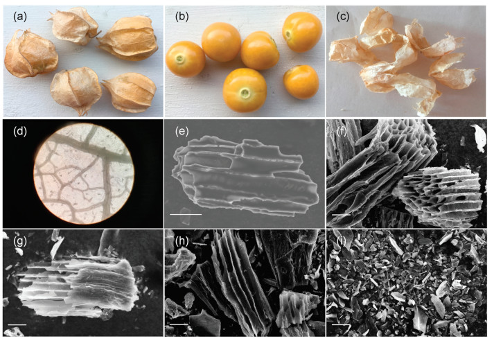
Goldenberry or cape gooseberry is a common fruit produced by the plant species Physalis peruviana L. (PC) (Solanaceae family), which mainly distribute in Northeast China and South America. As shown in Figs. 1a-c, it consists of two parts: the inner pulp which is edible and rich in nutrition substances for human body, and the outer calyx which protects the pulp from insects, birds, diseases and solar radiation. The calyx is thin as cicada's wings and rich in plant fiber and carbohydrates such as abscisic acid and jasmonic acid [19, 20], and the color could change from green to light yellow brown during the fruit ripening. Usually, the calyx is discarded after the pulp is used or eaten, so it could be a good source of biomass for carbon material.

|
Download:
|
| Fig. 1. (a) Photos of Physalis peruviana L. (b) The pulp and (c) the calyx. (d) Micrograph of PC. SEM images of (e) PCC-0, (f) PCC-1, (g) PCC-2, (h) PCC-3 and (i) PCC-4. Scale bar: 20 μm. | |
In this work, we generated a novel biomass carbon material (named PCC) derived from Physalis peruviana L. calyx. The results demonstrated that PCC performed long microtubule bundling with abundant O element on the surface. After chemical etching, PCC exhibited high specific capacitance with excellent cycling stability, which was expected to be utilized as an excellent electrode material in diverse renewable energy storage [21, 22].
The detailed preparation of PCC and electrochemical testing methods were as follows: Physalis peruviana L. calyxes were soaked in successively 1 mol/L HNO3, 1 mol/L KOH, 1 mol/L HCl and distilled water for 24 h, respectively, then washed by distilled water for three times and dried in oven at 40 ℃. After that, the pretreated calyxes were carbonized at 700 ℃ for 2 h with the nitrogen as the protection gas (100 mL/min). Cooling to the room temperature, Physalis peruviana L. calyx carbon material (PCC-0) was obtained. Then, PCC-0 was mixed with KOH at mass ratio MPCC-0:MKOH = 1:1, 1:2, 1:3 and 1:4, respectively. After grinded evenly, the mixtures were activated at 800 ℃ for 2 h with the nitrogen as the protection gas (100 mL/min). After that, the activated mixtures were cooling to the room temperature, then washed by 1 mol/L HCl and distilled water successively. After dried in oven at 40 ℃, the Physalis peruviana L. calyx activated carbon materials (PCC-X) were obtained, and named PCC-1, PCC-2, PCC-3 and PCC-4, respectively (corresponding to mass ratio MPCC-0: MKOH).
The electrochemical performance was evaluated through the conventional three-electrode system with Pt counter electrode, Hg/HgO reference electrode, 3 mol/L KOH aqueous solution electrolyte and the working electrode prepared by pressing the mixture of PCC, acetylene black and polyvinylidene fluoride (PVDF) with a mass ratio of 8:1:1 onto Ni foam.
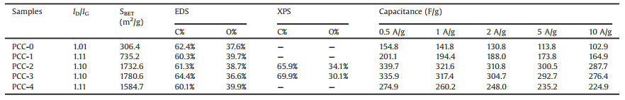
The microphotograph of PC and the SEM images of PCC were presented (Figs. 1d-i). As shown in Fig. 1d (100-fold by optical microscope), PC performed net veins microstructure with abundant large (≈ 270 μm) and fine (≈ 30 μm) pipelines which were interconnected with each other for water and nutrients transport in it. After carbonization, PCC-0 (Fig. 1e) exhibited long microtubule bundling with small through-holes on the pipeline shell, which were formed by the interconnected net vein of PC, suggesting that each of the net vein pipelines of PC consisted of many thinner pipelines in order. After grinding and etching at high temperature, PCC-1, PCC-2 and PCC-3 (Figs. 1f-h) preserved the microtubule bundling structures of PCC-0, but the wall of the pipelines in the bundling of PCC-X relatively exhibited thinner and the edge of the wall was slightly rough, while the pipeline wall of PCC-4, as shown in Fig. 1i, was completely destroyed and became fragments. Elemental analysis to PCC by Energy Dispersive Spectrometer (EDS) indicated that PCC was made of carbon atoms with abundant O (36.6%–39.9%) element on the surface, and the natural O quantity of PCC was relatively high compared to most of biomass carbon materials previously reported. The elemental atomic percentages of PCC were summarized in Table 1.
|
|
Table 1 Structural characteristics, surface information and capacitance of PCC. |
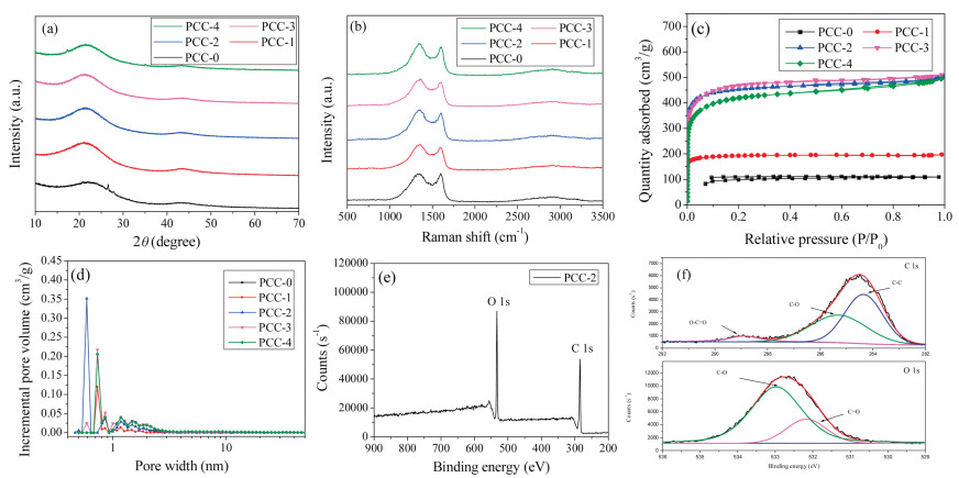
XRD patterns (Fig. 2a) showed two main broad diffraction peaks around 22.3 and 43.9 for PCC, which were attributed to the diffraction of (002) planes of the stacking of carbon turbostratic and (100) planes of the graphite lattice [23]. No sharp peaks appeared in the patterns, indicated that PCC was amorphous.

|
Download:
|
| Fig. 2. (a) XRD patterns, (b) Raman spectra, (c) N2 adsorption-desorption isotherms and (d) pore size distributions of PCC; (e) XPS survey spectra and (f) XPS high-resolution C 1s and O 1s of PCC-2. | |
Raman spectra (Fig. 2b) showed that the peak located at 1338 cm-1 was assigned to the sp3 carbon atoms which were disordered or defective (D band), and the peak located at 1586 cm-1 was attributed to the stretching bond of sp2 hybridized carbon at the graphitic layers (G band). The ID/IG ratios of PCC-X (1.10–1.11) were slightly higher than that of PCC-0 (1.01), confirming that PCC-X materials had more disordered and defective carbons because of the presence of the pores [24].
The specific surface areas of PCC were measured by N2 adsorption–desorption using the BET method. The results were shown in Fig. 2c and listed in Table 1. For PCC-0, the specific surface area was only 306.4 m2/g, and no volume adsorbed was observed from its isotherm in the low relative pressure range, indicating that there were little micropores in PCC-0. But after KOH etching, PCC-X exhibited larger specific surface areas and the N2 adsorption quantity performed sharp increases in the relative pressures ranging from 0 to 0.10, indicating that KOH etching had created more micropores at the wall surfaces [25]. The results confirmed that the optimal mass ratios (MPCC-0:MKOH) were 1:2 and 1:3, and the corresponding specific surface areas were 1732.6 m2/g for PCC-2 and 1780.6 m2/g for PCC-3, respectively. The pore size distributions of PCC-X calculated by the DFT method were shown in Fig. 2d, and it suggested the micropores of PCC-X mainly distributed in the range of 0.5–2.5 nm, which were ascribed to the KOH chemical etching.
The surface chemical properties of PCC-X were analyzed by Xray photoelectron spectroscopy (XPS). Figs. 2e and f showed the specific data of PCC-2. The survey spectra (Fig. 2e) exhibited two predominant peaks at about 285 eV and 531 eV corresponding to C 1s and O 1s, and the elemental contents were 65.9% for C and 34.1% for O, respectively. The abundant oxygen atom doping level of PCC-2 was much higher than that of recently reported heteroatomdoped carbon materials [5-18, 23, 26-31] owing to the natural oxygen content of the raw material (PC), indicating that it might make PCC-2 exhibit a special electrochemical property [26]. The C 1s and O 1s high resolution spectra were shown in Fig. 2f. The C 1s high resolution spectrum was resolved into three individual peaks centered on 284.4 (C–C/C=C), 285.3 (C–O) and 288.9 eV (O=C–O)[27], respectively, and the O 1s high resolution spectrum was resolved into two individual peaks centered on 532.2 (C=O) and 533.0 (C–O) [28], respectively.
The electrochemical capacitive properties of PCC used as electrode materials for supercapacitor were carried out in a three-electrode system. The cyclic voltammetry (CV) and galvanostatic charge-discharge (GCD) curves for PCC-0 and PCC-2 electrode materials were shown in Figs. 3a-d. Compared to PCC-0 electrode material, PCC-2 displayed larger area and rectangular-like shape even at higher scan rate, indicating that PCC-2 possessed larger specific surface areas and faster charge propagation and ion transport capability [29]. Both CV curves of PCC-0 and PCC-2 electrodes were observed bulge at lowpotential region, indicating the form of faradaic pseudocapacitance resulting from the higher oxygen quantity on the PCC surface [30, 31], and these oxygen elements were also beneficial to improve the wettability of the electrode carbon materials. The GCD curve of PCC-2 with more symmetrical curve and smaller voltage drop also indicated that the microporous structure could improve the contact at electrode/electrolyte interface, and further enhance the electrochemical performances [32], PCC-2 performed more reversible capacitive behavior and faster charge transfer property [33].

|
Download:
|
| Fig. 3. (a) Cyclic voltammetry curves of PCC-0 at different scanning rates (2–100 mV/s); (b) Galvanostatic charging/discharging curves of PCC-0 at different current density (0.5–10 A/g); (c) Cyclic voltammetry curves of PCC-2 at different scanning rates (2–100 mV/s); (d) Galvanostatic charging/discharging curves of PCC-2 at different current density (0.5–10 A/g); (e) Nyquist plots of PCC; (f) Stability of PCC-2 at 10 A/g. | |
The specific capacitances (Cm) of PCC samples at different current densities were listed in Table 1. In comparison to PCC-0, PCC-X exhibited higher specific capacitances, indicating that the enhancement of specific surface area and pore volume after KOH etching could significantly improve the specific capacitances [34]. The specific capacitances could be ordered as PCC-2 ≈ PCC-3>PCC-4>PCC-1>PCC-0, and PCC-2 performed the highest specific capacitance, which reached 339.7 F/g at 0.5 A/g.
Fig. 3e showed the Nyquist plots for PCC samples. Remarkably, the curves for PCC-2 showed the steepest slope of line and smallest diameter of semicircle, indicating that PCC-2 electrode performed the best capacitive behavior and the lowest diffusion resistance for electrolyte ions [35].
PCC-2 electrode also performed excellent stability. After 10, 000 cycles at 10 A/g, the capacitance retention of PCC-2 reached 97% (Fig. 3f). These excellent electrochemical performances were ascribed to the unique carbon structure with ordered microtubule bundling which was beneficial to the rapid ions transport and fast electron transfer.
In summary, biomass carbon materials PCC derived from Physalis peruviana L. calyx were facilely manufactured, and applied to supercapacitor. PCC performed long microtubule bundling structure with abundant O element (more than 30%) on the surface. After KOH chemical etching, PCC had much more pores and higher specific surface areas up to 1732.6 m2/g. For supercapacitor application, PCC exhibited high specific capacitance up to 339.7 F/g at 0.5 A/g in three-electrode system with excellent cycling stability (97% retention, 10, 000 cycles). PCC could have substantial potential for the energy storage applications including supercapacitors, Li-ion batteries, and hydrogen storage devices, etc.
AcknowledgmentsThe authors would like to thank Hebei Natural Science Foundation (No. B2015203259) and Key Laboratory of Advanced Energy Materials Chemistry (Ministry of Education), College of Chemistry, Nankai University for providing the financial support for this project.
| [1] |
Y.Y. Zhu, M.M. Chen, Q. Li, C. Yuan, C.Y. Wang, Carbon 129 (2018) 695-701. DOI:10.1016/j.carbon.2017.12.103 |
| [2] |
S.Y. Gao, M. Wang, Y. Chen, et al., Nano Energy 45 (2018) 21-27. DOI:10.1016/j.nanoen.2017.12.021 |
| [3] |
X.J. He, P.H. Ling, J.S. Qiu, et al., J. Power Sources 240 (2013) 109-113. DOI:10.1016/j.jpowsour.2013.03.174 |
| [4] |
Z. Ling, Z.Y. Wang, M.D. Zhang, et al., Adv. Funct. Mater. 26 (2016) 111-119. DOI:10.1002/adfm.201504004 |
| [5] |
X.M. Dong, H.L. Jin, R.Y. Wang, et al., Adv. Energy Mater. 8 (2018) 1702695. DOI:10.1002/aenm.201702695 |
| [6] |
X.L. Su, S.A. Jiang, G.P. Zheng, et al., J. Mater. Sci. 53 (2018) 9191-9205. DOI:10.1007/s10853-018-2208-5 |
| [7] |
X.L. Su, J.R. Chen, G.P. Zheng, et al., Appl. Surf. Sci. 436 (2018) 327-336. DOI:10.1016/j.apsusc.2017.11.249 |
| [8] |
G.X. Zhang, Y.M. Chen, Y.G. Chen, H.B. Guo, Mater. Res. Bull. 102 (2018) 391-398. DOI:10.1016/j.materresbull.2018.03.006 |
| [9] |
B. Liu, M. Yang, D.G. Yang, H.B. Chen, H.M. Li, Int. J. Hydrogen Energy 43 (2018) 18270-18278. DOI:10.1016/j.ijhydene.2018.08.059 |
| [10] |
Y.B. Zhou, J. Ren, L. Xia, et al., Electrochim. Acta 284 (2018) 336-345. DOI:10.1016/j.electacta.2018.07.134 |
| [11] |
X.C. Yan, Y. Jia, L.Z. Zhuang, et al., Chemelectrochem 5 (2018) 1874-1879. DOI:10.1002/celc.201800068 |
| [12] |
F.M. Zeng, Z. Li, X.Y. Li, et al., Appl. Surf. Sci. 467 (2019) 229-235. |
| [13] |
J. Niu, M.Y. Liu, F. Xu, et al., Carbon 140 (2018) 664-672. DOI:10.1016/j.carbon.2018.08.036 |
| [14] |
J. Yin, Y.Y. Fan, J.H. Wu, Y.M. Xie, ChemistrySelect 3 (2018) 8144-8150. DOI:10.1002/slct.201801057 |
| [15] |
Z.Y. Wu, L. Fan, Y.R. Tao, et al., Chin. J. Inogy. Chem. 34 (2018) 1249-1260. |
| [16] |
B. Liu, M. Yang, D.G. Yang, H.B. Chen, H.M. Li, Electrochim. Acta 272 (2018) 88-96. DOI:10.1016/j.electacta.2018.04.001 |
| [17] |
Z.H. Chen, H. Zhuo, Y.J. Hu, et al., ACS Sustain. Chem. Eng. 6 (2018) 7138-7150. DOI:10.1021/acssuschemeng.8b01159 |
| [18] |
L. Zhang, L. Xu, Y.G. Zhang, et al., RSC Adv. 8 (2018) 3869-3877. DOI:10.1039/C7RA11475C |
| [19] |
F. Gerhard, L. Peter, Agron. Colomb. 14 (1997) 95-107. |
| [20] |
F. Alvarez, C.L. Cristoffanini, O. Jauregui, L.M. Melgarejo, M. Lopez Carbonell, Plant Physiol. Biochem. 115 (2017) 174-182. DOI:10.1016/j.plaphy.2017.03.024 |
| [21] |
H.J. Wang, L. Zhi, K.Q. Liu, et al., Adv. Funct. Mater. 25 (2015) 5420-5427. DOI:10.1002/adfm.201502025 |
| [22] |
X.J. He, N. Zhao, J.S. Qiu, et al., J. Mater. Chem. A 1 (2013) 9440-9448. DOI:10.1039/c3ta10501f |
| [23] |
D. Yu, Y.S. Ma, M.F. Chen, X.P. Dong, J. Colloid Interf. Sci. 537 (2019) 569-578. DOI:10.1016/j.jcis.2018.11.070 |
| [24] |
Y. Han, X.T. Dong, C. Zhang, S.X. Liu, J. Power Sources 211 (2012) 92-96. DOI:10.1016/j.jpowsour.2012.03.053 |
| [25] |
J. Choi, C. Lee, S. Cho, et al., Carbon 132 (2018) 16-24. DOI:10.1016/j.carbon.2018.01.105 |
| [26] |
L.Z. Sheng, L.L. Jiang, T. Wei, Z. Liu, Z.J. Fan, Adv. Energy Mater. 7 (2017) 1700668. DOI:10.1002/aenm.201700668 |
| [27] |
R.S. Fu, Z.Z. Chang, C.X. Shen, et al., Electrochim. Acta 260 (2018) 430-438. DOI:10.1016/j.electacta.2017.12.043 |
| [28] |
J. Niu, J.J. Liang, R. Shao, et al., Nano Energy 41 (2017) 285-292. DOI:10.1016/j.nanoen.2017.09.041 |
| [29] |
M.Y. Song, Y.H. Zhou, X. Ren, et al., J. Colloid. Interf. Sci. 535 (2019) 276-286. DOI:10.1016/j.jcis.2018.09.055 |
| [30] |
Z.H. Zou, W.J. Zhou, Y.H. Zhang, et al., Chem. Eng. J. 357 (2019) 45-55. DOI:10.1016/j.cej.2018.09.143 |
| [31] |
W.F. Liu, Y.Z. Yang, X.G. Liu, B.S. Xu, New. Carbon. Mater. 31 (2016) 594-599. DOI:10.1016/S1872-5805(16)60035-5 |
| [32] |
J. Xu, Z.Q. Tan, W.C. Zeng, et al., Adv. Mater. 28 (2016) 5222-5228. DOI:10.1002/adma.201600586 |
| [33] |
S.L. Wang, N.S. Liu, J. Su, et al., ACS Nano 11 (2017) 2066-2074. DOI:10.1021/acsnano.6b08262 |
| [34] |
B. You, F. Kang, P.Q. Yin, Q. Zhang, Carbon 103 (2016) 9-15. DOI:10.1016/j.carbon.2016.03.009 |
| [35] |
E.H. Mohan, K. Nanaji, S. Anandan, et al., Mater. Lett. 236 (2019) 205-209. DOI:10.1016/j.matlet.2018.10.044 |