 2020, Vol. 31


b Jiangsu Engineering Laboratory of Smart Carbon-Rich Materials and Device, School of Chemistry and Chemical Engineering, Southeast University, Nanjing 211189, China
Hierarchical structures widely exist in nature. Among these structures, hierarchically porous networks are of particular importance in mass transportation, etc. [1-3]. For instance, plants contain stem and leaf veins. The parent stems are connected with various narrowing children veins, forming branch networks which cover the whole surfaces of the plants. Such porous channels facilitate transferring and exchange of water, gas, and organics, therefore optimizing the photosynthesis [4-7]. Animals also use similar hierarchical structure in respiratory system and vasculature. The multi-level branches help to deliver blood to everywhere and exchange the CO2 and O2 molecules efficiently for breathing [4-6, 8]. Besides organisms, the earth utilizes hierarchical structure as well. Rivers usually contain uncountable branches which can capture a huge amount of water as well as sands towards the ocean [9, 10].
Various efforts have been devoted into fabrication of hierarchical pores in materials. Micropores (< 2 nm), mesopores (2–50 nm) and macropores (> 50 nm) have been successfully integrated into one material [11-16]. However, a challenge in maximizing the power of the hierarchically porous networks is to find optimized diameter/length ratios among the multi-scale pores. Instead of the trial and error strategy, nature has its own ways to optimize the multi-scale pore structure [17-19]. For example, organisms obey a quantified relationship to precisely keep the diameter ratios for connecting multi-scale pores from macroscopic to microscopic levels as elucidated by Murray in 1926. These networks allow an optimized mass transportation and exchange efficiency [20]. Following the Murray's principle, bottom-up has been considered as the first trial for building up hierarchically porous networks [2, 6]. A bottom-up layer-by-layer evaporation-driven self-assembly strategy was used to fabricate hierarchically porous network materials which exhibited highly enhanced performance in applications need mass or electrons transfer and exchange, such as photocatalysis, gas sensing and energy storage applications [6, 21].
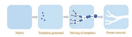
Despite the success in bottom up assembly, the unavoidable careful selection and manipulation of the templates drive a practical application to be difficult sometimes. An alternative strategy selected by nature has been developed [22, 23]. The rivers are huge, may be the largest, hierarchical networks on the earth. Formation of these networks strongly depends on flow of the water and etching of the passed area. Without precise designing, most part of the networks work efficiently in carrying water and other mass for many years [24, 25]. Here, we mimic the formation of river systems by utilization of mobile templates during the formation of porous carbons. The templates are generated inside the materials in situly. Hierarchically porous networks with multi-scale pores from macropores to micropores are obtained as a result of moving of the templates. By using this strategy, porous carbons can be fabricated (Fig. 1).

|
Download:
|
| Fig. 1. Schematic illustration for hierarchically porous networks forming by immigration of templates. | |
There are existing methods in fabrication of hierarchically porous carbons. Soft-template strategy [13], dual-template approach [26], or biomass carbonization [27] have all been developed. Comparing the existing methods, the approach reports in this work is expected to borrow the power of self-diffusion used by nature.
In this report, we chose Prussian blue (PB, Fe4[Fe(CN)6]3), as precursor for carbonization due to its high metal to cyanide composition [28, 29]. The Fe nodes not only served as a catalyst for graphitization of the carbons, but also reacted with the oxygen ions to generate iron oxides which became mobile templates [30, 31]. The iron oxides moved from the interior to the external shell spontaneously. The migration pathways become hierarchically porous networks like the networks formed by river flowing.
The scheme was illustrated in Fig. S1 (Supporting information). Because PB has a low carbon content (25%) [32], it is necessary to add second carbon sources into the PB crystals. Considering that the intrinsic pore of the PB is too small (0.4–0.7 nm) to accept organic molecules, we create mesopore and macropores in PB crystals first. In brief, PB particles were etched by acid with a surface protection method [33]. Scanning electron microscopy (SEM) and transmission electron microscopy (TEM) demonstrated that hierarchically porous PB particles were formed (Figs. S2a and b in Supporting information). The porosity was analyzed by N2 adsorption-desorption isotherms (Fig. S3 in Supporting information). There is a sharp rise of the uptake in the low relative pressure region, indicating the presence of intrinsic micropores. In the range of P/P0 = 0.45∼1.0, a hysteresis loop provides a direct evidence for the existence of mesopores and macropores coming from etching. Furfuryl alcohol (FA) was filled into the pores as as the second carbon source. The FA molecule has a high content of C about 61%, and a molecular dimension of 8.43 Å × 6.44 Å × 4.28 Å which is suitable to penetrate into the mesopores [34]. After filling the FA molecules, the porosity of of PB particles was evaluated by N2 sorption again. The isothermpresented no hysteresis loop, implying that the FA molecules were successfully loaded. Infrared spectrum taken from the infiltrated PB particles also suggests this deduction as shown in Fig. S4 (Supporting information). Several bands were observed at 3250 cm–1, 2920 cm–1, 1600 cm–1 and 1420 cm–1, which were ascribed to vibration and deformation of the —OH, —CH2—, —HC=CH—, and C—O groups, respectively. These groups all belong to the filled FA molecules [35].
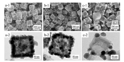
The samples were then carbonized by annealing at various temperatures under the protection of N2 flow for 5 h. SEM and TEM images of the samples are illustrated in Fig. 2. The particles annealed at 500 ℃ and 600 ℃ inherit the origin shape of the PB precursors although the surface structures have been changed. Many aggregated crystallites have been observed on the surfaces. When the sample was heated at 700 ℃, the obtained particles have few crystallites on the surface, and many mesopores were observed on the surfaces. In addition to the cubic particles, some free-standing polyhedral particles were found with dense surfaces.

|
Download:
|
| Fig. 2. SEM and TEM images of the carbonized samples obtained at different annealing temperatures: (a) 500 ℃, (b) 600 ℃ and (c) 700 ℃. | |
To clarify the crystal structure of the samples, powder X-ray diffraction (XRD) was employed (Fig. S5 in Supporting information). The diffraction profiles contain a broad peak at 26° which belongs to (002) of graphitic carbon. The other diffraction peaks are all indexed to a spinel structure which is typical for Fe3O4 (JCPDS card No. 75-0449) [36]. Compared with the samples annealed at 500 ℃ and 600 ℃, the sample heated at 700 ℃ has sharper diffraction peaks, indicating the large polyhedral particles are Fe3O4. Formation of the Fe3O4 is due to the oxidization role of the added FA molecules.
It seems like that the Fe3O4 crystallites were extruded from the particles with increase of the annealing temperature. To confirm this deduction, we investigated a time course shape change of the samples (Fig. S6 in Supporting information). By setting the annealing temperature at 500 ℃, SEM images of the samples were captured at different time. The Fe3O4 crystallites were formed and distributed uniformly inside the particles. Then the crystallites aggregated at the outer shell, and grew larger with elongation of the annealing time, indicating an immigration of the Fe3O4 crystallites. The XRD profiles also confirmed this growth. When the annealing time continued, the diffraction peaks of the Fe3O4 became sharper. The half height width corresponds to the crystal sizes according to the Scherrer formula [37, 38]. Therefore, the sharper the diffraction peak, the larger the crystal size.
We removed the Fe3O4 crystallites by hydrochloride acid. All the three samples after etching were shown in Fig. 3. SEM images revealed that the samples retained the shape of the initial cubic PB. Besides, mesopores larger than 20 nm in size could be observed on the surface of the PB. TEM images illustrates that the whole particles are highly porous. All the pores are interconnected with each other. No crystallites could be observed, implying that Fe3O4 were completely removed. X-ray photoelectron spectroscopy (XPS) was employed to confirm this point again (Fig. S7a in Supporting information). The spectrum shows three peaks which correspond to C, N and O elements. The Fe 2p spectrum (Fig. S7b in Supporting information) displays that the spectral line oscillates near the baseline without forming a significant peak, suggesting that no Fe exists. We examined the obtained porous samples further by XRD (Fig. S8 in Supporting information). All the samples exhibit a broad peak centered at 26° approximately, which was correlated to (002) plane of graphite (JCPDS No. 75-0444). Such diffraction profiles are typical for activated carbons [39]. We employed Raman spectroscopy to investigate the sample in details (Fig. S9 in Supporting information). The intense broad bands located on 1350 cm–1 is D-band which represents disordered carbon. Another brand at 1590 cm–1 is assigned to G-band of graphitized carbon due to the graphitic sp2-hybridization in the carbon structure [40]. The ID/IG intensity ratios of the carbons obtained at 500 ℃, 600 ℃ and 700 ℃ were determined to be 0.96, 0.86, 0.74, respectively. In consequence, increase of the annealing temperature results in higher graphitic degree. This conclusion is also supported by XPS. Fig. S10 (Supporting information) shows the N 1s spectrum which can be divided into three components, corresponding to nitrogen atoms in different state. N1 peak at around 398.6 eV represents pyridinic nitrogen. N2 peak at near 400.2 eV represents pyrrolic nitrogen with defects, and N3 peak at around 401 eV is on behalf of graphitic nitrogen [41, 42]. The area of N3 correlates to the graphitization degree. For the three samples, the content of N3 is 31.2%, 42.7%, 45.6%, respectively. In addition, we did an element analysis test for N element (Table S1 in Supporting information). With increase of the temperature, the N content of the three samples were 3.69, 2.57 and 2.47, respectively.

|
Download:
|
| Fig. 3. SEM and TEM images of the etched carbons which were carbonized at 500 ℃ (a), 600 ℃ (b) and 700 ℃ (c). | |
The hierarchical porosity was analyzed by nitrogen adsorption-desorption isotherms (Fig. S11 in Supporting information). Each isotherm shows a steady uptake at the low relative pressure, indicating existence of the micropores. There are hysteresis loops at higher relative pressures from 0.1–0.7, suggesting the existence of mesopores. The distribution of pore size was calculated by non-local density functional theory (NLDFT) method. Each sample contains various kinds of pores in multi-scale, such as micropores (less than 1 nm), small mesoporous (from 3 nm to 20 nm), and big mesopores (more than 20 nm). Considering the macropores exist inside each particle, the samples are all micro-meso-macroporous materials. Their specific surface areas and pore volumes were listed in Table S2 (Supporting information).
To illustrate the characteristic of the hierarchically porous carbons in practical applications, we assembled prototype Na/carbon half-cell. Na-ion batteries are potential alternatives for Li-ion battery because of the abundance of Na-ion sources all over the world. However, the electrodes which can accommodate Na+ ions need to be explored due to the larger radius of Na+ ions than Li+ ions [43-49]. The hierarchical pores in our case are expected to enhance diffusion and adsorption of Na+ ions during electrochemical processes [50-52]. For comparison, hard carbons which have been used mostly in practical applications have been used as well. Before testing, the specific surface area and porosity of the hard carbon and our hierarchically porous carbon sample (annealed at 500 ℃) have been compared as shown in Table S3 (Supporting information).
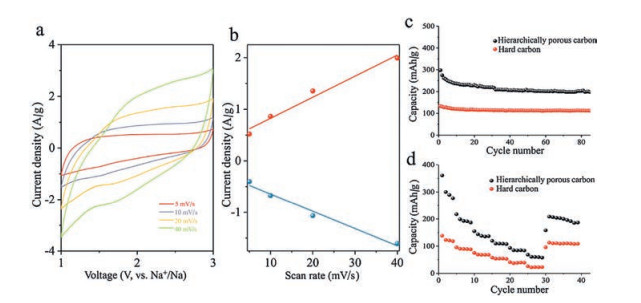
There are two typical characteristics for intercalation of the Na+ ions. According to the kinetics of the Na-ion storage and the shape of cyclic voltammograms (CV) curves respectively [53, 54]. When the CV curve contain faradaic redox peaks, the intercalation is battery-type. While the CV curve is quasi-rectangular, it represents a pseudocapacitor-type intercalation [53-55]. On the other hand, the formula i= Cνb (i represents the current, ν represents the sweep rate, and C and b are constants) describes the ion intercalation kinetics. If b < 1, the kinetics is hyperbolic, indicating a battery-type intercalation. When the kinetics is linear (b = 1), the intercalation is pseudocapacitor-type [53, 54, 56, 57]. From Fig. 4, we investigated the kinetic information from the CV curves at different sweeping rates of 5 mV/s, 10 mV/s, 20 mV/s, and 40 mV/s. It is clearly that the CV curves of the hierarchically porous carbon shows a quasi-rectangular shape, and the kinetics is linearly fitted with I = Cν. Therefore, the hierarchically porous carbon has a pseudocapacitor-type ion storage. This ion storage behavior is due to the hierarchically porous structure. The guest ions do not need to penetrate into the graphitic layers but can easily access to the surface of the carbons.

|
Download:
|
| Fig. 4. (a) CV curves of the hierarchically porous carbon at various scan rates. (b) The dependence of anodic and cathodic current (at 2 V) on scan rate. Cycling performance (c) and rate performance (d) of the hierarchically porous carbon and the hard carbon. | |
The pseudocapacitor-type intercalation results in the higher charge storage [58, 59]. As showed in the cycling performance at a current density of 50 mA/g, the hierarchically porous carbons delivered the discharge capacity of 300 mAh/g in the first cycle. After 100 cycles, the capacity remained 200 mAh/g. In contrast the electrodes made by the hard carbons had a discharge capacity of 130 mAh/g in the first cycle, and remained 100 mAh/g after 80 cycles. Consequently, the hierarchically porous structure contributed to the improved Na+ ions storage. In addition, we took a rate performance test at high current densities. The hierarchically porous carbon and hard carbon have the capacity about 361 mAh/g and 148 mAh/g at low current density of 50 mA/g, respectively. When the current density was increased to 2000 mA/g, the capacity decreased to 68 mAh/g and 25 mAh/g, respectively. Once the current density went back to 50 mA/g, the reversible capacities were recovered to 208 mAh/g and 95 mAh/g.
In summary, we developed a strategy by utilizing mobile templates to fabricate hierarchically porous networks with multi-scale pores from macropores to micropores. The generation and immigration of the Fe3O4 crystallites during thermal pyrolysis of the Prussian blue cages should be responsible for the porous channels. The porous structure led to a pseudocapacitor-type intercalation type, therefore enhanced the capacities of carbon based electrodes.
AcknowledgmentThis work was supported by the National Natural Science Foundation of China (No. 21473059).
Appendix A. Supplementary dataSupplementary material related to this article can be found, in the online version, at doi:https://doi.org/10.1016/j.cclet.2019.04.006.
| [1] |
J. Aizenberg, J.C. Weaver, M.S. Thanawala, et al., Science 309 (2005) 275-278. DOI:10.1126/science.1112255 |
| [2] |
X. Wang, Z. Huang, D. Miao, et al., ACS Nano 13 (2019) 1060-1070. |
| [3] |
A. Bejan, J.P. Zane, Mech. Eng. 134 (2012) 42-47. |
| [4] |
K.A. McCulloh, J.S. Sperry, F.R. Adler 421 (2003) 939-942. |
| [5] |
G.B. West, J.H. Brown, B.J. Enquist, Science 276 (1997) 122-126. DOI:10.1126/science.276.5309.122 |
| [6] |
X. Zheng, G. Shen, C. Wang, et al., Nat. Commun. 8 (2017) 14921. DOI:10.1038/ncomms14921 |
| [7] |
M.R. Carvalho, J.M. Losada, K.J. Niklas, Curr. Opin. Plant Biol. 43 (2018) 29-35. DOI:10.1016/j.pbi.2017.12.007 |
| [8] |
S.K. Hetz, T.J. Bradley, Nature 433 (2005) 516-519. DOI:10.1038/nature03106 |
| [9] |
G.B. Pasternack, D. Baig, M.D. Weber, et al., Earth Surf. Process. Landforms 43 (2018) 2510-2518. DOI:10.1002/esp.4411 |
| [10] |
G.B. Pasternack, D. Baig, M.D. Weber, et al., Earth Surf. Process. Landforms 43 (2018) 2519-2532. DOI:10.1002/esp.4410 |
| [11] |
Y. Lv, L. Gan, M. Liu, et al., J. Power Sources 209 (2012) 152-157. DOI:10.1016/j.jpowsour.2012.02.089 |
| [12] |
J. Xu, W. Zhang, D. Hou, et al., Chin. Chem. Lett. 28 (2017) 2295-2297. DOI:10.1016/j.cclet.2017.10.041 |
| [13] |
L. Sun, Y. Zhou, L. Li, et al., Appl. Surf. Sci. 467- 468 (2019) 382-390. |
| [14] |
L. Shen, X. Zheng, G. Lei, et al., Chem. Eng. J. 346 (2018) 238-248. DOI:10.1016/j.cej.2018.03.157 |
| [15] |
P.K. Tripathi, M. Liu, Y. Zhao, et al., J. Mater. Chem. A 2 (2014) 8534-8544. DOI:10.1039/c4ta00578c |
| [16] |
M. Liu, L. Gan, Y. Li, et al., Chin. Chem. Lett. 25 (2014) 897-901. DOI:10.1016/j.cclet.2014.01.010 |
| [17] |
D. Jing, S. Song, L. He, Int. J. Heat Mass Transfer 128 (2019) 1344-1350. DOI:10.1016/j.ijheatmasstransfer.2018.08.006 |
| [18] |
J. Kou, Y. Chen, X. Zhou, et al., Physica A 393 (2014) 527-534. DOI:10.1016/j.physa.2013.08.029 |
| [19] |
D.R. Emerson, K. Cieślicki, X. Gu, et al., Lab Chip 6 (2006) 447-454. DOI:10.1039/b516975e |
| [20] |
C.D. Murray, Proc. Natl. Acad. Sci. USA 12 (1926) 207-214. DOI:10.1073/pnas.12.3.207 |
| [21] |
Z. Wang, T. Liu, Y. Yu, et al., Small 14 (2018) 1802670. DOI:10.1002/smll.201802670 |
| [22] |
G.S. Kassab, Am. J. Physiol. Heart Circ. Physiol. 290 (2006) H894-H903. DOI:10.1152/ajpheart.00579.2005 |
| [23] |
A. Kamiya, T. Takahashi, J. Appl. Physiol. 102 (2007) 2315-2323. DOI:10.1152/japplphysiol.00856.2006 |
| [24] |
M. Colombini, A. Stocchino, J. Fluid Mech. 695 (2012) 63-80. DOI:10.1017/jfm.2011.556 |
| [25] |
S.N. Wilkinson, R.J. Keller, I.D. Rutherfurd, Earth Surf. Process Landforms 29 (2004) 737-753. DOI:10.1002/esp.1066 |
| [26] |
Y. Deng, C. Liu, T. Yu, et al., Chem. Mater. 19 (2007) 3271-3277. DOI:10.1021/cm070600y |
| [27] |
Z. Wu, K. Tian, T. Huang, et al., ACS Appl. Mater. Interfaces 10 (2018) 11108-11115. DOI:10.1021/acsami.7b17264 |
| [28] |
M. Hu, A.A. Belik, M. Imura, et al., J. Am. Chem. Soc. 135 (2012) 384-391. |
| [29] |
R. Ojani, P. Hamidi, J. Raoof, Chin. Chem. Lett. 27 (2016) 481-486. DOI:10.1016/j.cclet.2015.12.030 |
| [30] |
Y. Liang, J. Wei, X. Zhang, et al., ChemCatChem 8 (2016) 1901-1904. DOI:10.1002/cctc.201501402 |
| [31] |
R. Qiang, Y. Du, H. Zhao, et al., J. Mater. Chem. A 3 (2015) 13426-13434. DOI:10.1039/C5TA01457C |
| [32] |
C. Clauss, M. Schwarz, E. Kroke, Carbon 48 (2010) 1137-1145. DOI:10.1016/j.carbon.2009.11.036 |
| [33] |
M. Hu, S. Furukawa, R. Ohtani, et al., Angew. Chem. Int. Ed. 51 (2012) 984-988. DOI:10.1002/anie.201105190 |
| [34] |
B. Liu, H. Shioyama, T. Akita, et al., J. Am. Chem. Soc. 130 (2008) 5390-5391. DOI:10.1021/ja7106146 |
| [35] |
T. Kim, J. Jeong, M. Rahman, et al., Korean J. Chem. Eng. 31 (2014) 2124-2129. DOI:10.1007/s11814-014-0322-x |
| [36] |
R. Rahmawati, M.G. Permanaa, B. Harisona, et al., Procedia Eng. 170 (2017) 55-59. DOI:10.1016/j.proeng.2017.03.010 |
| [37] |
D. Smilgies, J. Appl. Crystallogr. 42 (2009) 1030-1034. DOI:10.1107/S0021889809040126 |
| [38] |
L. Wang, Y. Yu, P.C. Chen, et al., J. Power Sources 183 (2008) 717-723. DOI:10.1016/j.jpowsour.2008.05.079 |
| [39] |
X. Chen, F. He, Y. Shen, et al., Chem.-Eur. J. 23 (2017) 14597-14603. DOI:10.1002/chem.201703020 |
| [40] |
L. Wang, Y. Wang, M. Wu, et al., Small 14 (2018) 1800737. DOI:10.1002/smll.201800737 |
| [41] |
Z. Zhou, F. He, Y. Shen, et al., Chem. Commun. 53 (2017) 2044-2047. DOI:10.1039/C6CC09442B |
| [42] |
M. Wu, Y. Wang, Z. Wei, et al., J. Mater. Chem. A 6 (2018) 10918-10925. DOI:10.1039/C8TA02416B |
| [43] |
J. Liang, Z. Wei, C. Wang, et al., Electrochim. Acta 285 (2018) 301-308. DOI:10.1016/j.electacta.2018.07.230 |
| [44] |
C. Zhu, X. Mu, P.A. van Aken, et al., Angew. Chem. Int. Ed. 53 (2014) 2152-2156. DOI:10.1002/anie.201308354 |
| [45] |
Y. Chen, B. Wang, T. Hou, et al., Chin. Chem. Lett. 29 (2018) 187-190. DOI:10.1016/j.cclet.2017.06.019 |
| [46] |
S. Liu, L. Shao, X. Zhang, et al., Acta Phys.-Chim. Sin. 34 (2018) 581-597. |
| [47] |
X. Zhang, Y. Huang, S. Wu, et al., Acta Phys.-Chim. Sin. 34 (2018) 219-226. |
| [48] |
Q. Ma, Y. Hu, H. Li, et al., Acta Phys.-Chim. Sin. 34 (2018) 213-218. |
| [49] |
W. Song, H. Hou, X. Ji, Acta Phys.-Chim. Sin. 33 (2017) 103-129. |
| [50] |
L. Fu, K. Tang, K. Song, et al., Nanoscale 6 (2014) 1384-1389. DOI:10.1039/C3NR05374A |
| [51] |
X. Ma, L. Gan, M. Liu, et al., J. Mater. Chem. A 2 (2014) 8407-8415. DOI:10.1039/C4TA00333K |
| [52] |
Y. Fang, Z. Chen, X. Ai, et al., Acta Phys.-Chim. Sin. 33 (2017) 211-241. |
| [53] |
Y. Gogotsi, R.M. Penner, ACS Nano 12 (2018) 2081-2083. DOI:10.1021/acsnano.8b01914 |
| [54] |
W. Zhang, X. Jiang, Y. Zhao, et al., Chem. Sci. 8 (2017) 3538-3546. DOI:10.1039/C6SC04903F |
| [55] |
T. Brousse, D. Bélanger, J.W. Long, J. Electrochem. Soc. 162 (2015) A5185-A5189. DOI:10.1149/2.0201505jes |
| [56] |
J. Liu, J. Liang, C. Wang, et al., J. Energy Chem. 33 (2019) 160-166. DOI:10.1016/j.jechem.2018.09.006 |
| [57] |
M. Zhao, L. Zhu, B. Fu, et al., Acta Phys.-Chim. Sin. 35 (2019) 193-199. |
| [58] |
P. Simon, Y. Gogotsi, B. Dunn, Science 343 (2014) 1210-1211. DOI:10.1126/science.1249625 |
| [59] |
V. Augustyn, J. Come, M.A. Lowe, et al., Nat. Mater. 12 (2013) 518-522. DOI:10.1038/nmat3601 |