 2020, Vol. 31

Graphene, as a sheet-like allotrope of carbon, has received widespread attention in energy storage field due to its large specific surface area, high conductivity and excellent mechanical properties [1-3]. Previously, many graphene-based composites utilize graphene as frameworks for active materials [4, 5]. The synthesis of scalable composite membranes for energy storage is often based on the processable aqueous reduced graphene oxide (rGO) [6, 7]. Owing to the colloidal chemistry interactions of rGO sheets, it is favorable for active materials to synthesize composites through solid-liquid interface assembly techniques [4, 8-11]. However, it remains a challenge for rGO to form stable combination with the components and obtain uniform structure since the anisotropic surface groups and hydrophobic forces capture the dominant role on the layers, which easily leads to agglomeration in the liquid phase [12]. Furthermore, structural regulation plays an important role in constructing two-dimensional membranes [13].
Graphene oxide (GO) [14], as the precursor of graphene, can be viewed as amphiphilic macromolecules with conjugated domains and abundant oxygen-containing functional groups [1, 6, 14-16], which can play the role of surfactants to disperse low-polarity active materials, for example, graphite and CNT, in water [14, 17, 18]. After chemical or thermal reduction, the resulting composite structure can retain the uniformity and exhibit high electrical conductivitysimultaneously. Therefore, the GO has been suggested to be a promising candidate for fabricating uniform and stable composite membranes.
Herein, we demonstrated that active particles (graphite, ~15 μm) can perform as freestanding and uniform membrane in the assistance of GO which owns amphiphilic and polymer-like properties [19-21], and with the help of freeze casting in maintaining the uniformity [22]. The simple freeze casting effectively avoids the defects of voids and severe aggregation which occur in other solvent-removing process involving capillary forces. Consequently, the active particles are firmly wrapped and uniformly dispersed in the GO foam. The integral structure can be directly compacted into a freestanding membrane owing to the plasticity of GO, which can be used as electrode in batteries after reduction. In addition, the feasibility of the method is also verified by the successful fabrication of the freestanding membranes with other micrometer-sized materials LiFePO4 and hard carbon.
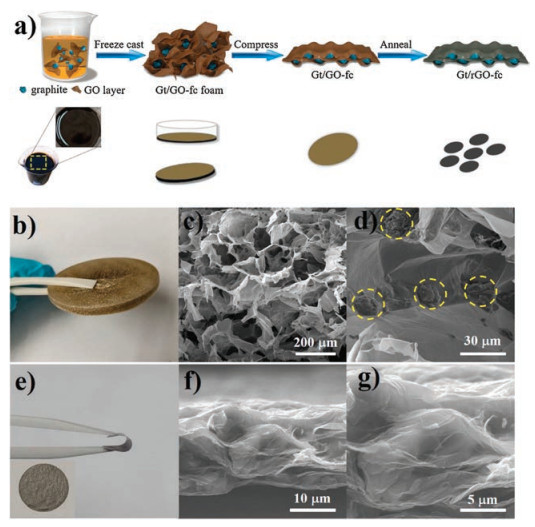
Fig. 1a schematically shows the fabrication processes of graphite/rGO membranes by freeze casting (Gt/rGO-fc). The precursor, GO sheets, serves as the surfactant to disperse the hydrophobic graphite particles in water. After freeze casting process, a brown foam is obtained. Among various strategies, freeze casting is a readily accessible and versatile solution-phase approach that can employ the controlled crystallization of a suspension to induce uniform porous architectures. During the drying process, the solidified frozen solvent template sublimates from the solid to the gas phase under reduced pressure and then the uniform mixing state of GO layers and graphite particles is maintained. Thus, the obtained foam can be mechanically pressed into a freestanding and continuous film due to the polymer-like plasticity and extensibility properties of GO layers [23]. After annealing, the structure is still retained, which is favorable for facilitating electron transport when Gt/rGO-fc membranes are used for freestanding electrodes.

|
Download:
|
| Fig. 1. (a) Schematic illustration of the fabrication process of Gt/rGO-fc membrane by freeze casting, compaction, annealing process. (b, e) Photographs of Gt/GO-fc foam (b) and Gt/rGO-fc membrane (e). (c, d) SEM images of the cross section of Gt/GO foam (the micrometer-sized graphite particles are marked by dotted circles). (f, g) SEM images of the cross section of Gt/rGO-fc membrane with different magnitudes. | |
Scanning electron microscopy (SEM) (Figs. 1c and d) images indicate the porous structure of Gt/GO-fc foam. Graphite particles can be seen clearly in the pores of graphene oxide framework. A conductive Gt/rGO-fc film is fabricated by mechanically pressing at 5 MPa and subsequent annealing at 1000 ℃, as shown in Figs. 1e–g. The SEM images indicate the Gt/rGO-fc film has a lamellar structure where the graphite particles are evenly encapsulated in a continuous rGO network. At the same time, the existence of the μm-scale graphite results in the relatively lose stacking of rGO sheets and is favorable to the transport of electrons and ions [13]. Fig. S1 (Supporting information) shows the microstructure of rGO membrane by freeze casting (rGO-fc). As seen, the rGO layers are closely restacked together without the spacer effect from guest particles [24], which may create barriers to electrolyte infiltration and ions transport [25]. In addition, the mass ratio of graphite and rGO in Gt/rGO-fc membrane is 4:1, which is consistent with the conventional graphite slurry electrode (Gt-slurry) in the experiments. We choose Gt/rGO-fc film with the weight ratio of 4:1 as the electrode in lithium batteries, which is consistent with the conventional graphite electrodes (Gt-slurry) made by casting slurries of active materials, conductive agents and binders (8:1:1 by weight) on copper foil current collector (Fig. S2 in Supporting information).
Importantly, the sequence of pressing and annealing makes a difference. If the Gt/GO-fc foam is annealed before being pressed, the obtained Gt/rGO-fc foam easily fractures when pressed (Fig. S3 in Supporting information), which may be ascribed to the higher rigidity of rGO than that of GO sheets and fails to obtain an integral membrane. The plasticity of GO sheets makes them easy to compact without fracture.
To probe the role of freeze-casting step in membrane preparation, we fabricate the composite membranes by different solvent-removing methods–that is, freeze-casting, natural drying and vacuum filtration. The corresponding membranes are denoted as Gt/rGO-fc, Gt/rGO-nd and Gt/rGO-vf, respectively. As shown in Fig. 2, the resulting Gt/rGO-fc, Gt/rGO-nd and Gt/rGO-vf membranes show different appearances and microstructures. Initially, the graphite particles are uniformly dispersed in the GO solution. In the case of Gt/rGO-fc, the numerous ice crystals formed in the fast freezing step pushes the adjacent GO sheets and graphite particles together to generate the walls in the honeycomb-like network. The good dispersity in the dispersion state is thus well maintained. Then after compaction and annealing, the graphite particles are evenly encapsulated in rGO layers. The film holds an oriented and integral structure as shown in Figs. 2a–c. And the graphene constituent also shows an obvious crumpled structure. In the case of Gt/rGO-nd, when the uniform mixing dispersion of graphite particles and GO is naturally dried (under normal pressure), besides the flat bottom of the vessel, the particles also serve as the substrates that influence the stacking direction. Therefore, in the spot around the micrometer-sized particles, solvent evaporation-induced shrinkages of the GO stacks go in different directions, which causes the crack if the GO film cannot withstand the internal stress from capillary force during evaporation, as shown in Figs. 2e and f. At the same time, as the concentration increases during solvent evaporation, the particles in the dispersion tend to aggregate to reduce the surface energy—that is, phase separation happens (Fig. 2f). In the case of Gt/GO-vf, although GO sheets increase the dispersity of the graphite particles to a degree, the particles would still sediment earlier than the GO sheets in the long time that filtration takes. As a result, Gt/GO-vf also has the problem of particle aggregation, as illustrated in Fig. 2i. The large aggregates even cause tens of micrometer-sized voids in the dried film (Fig. 2h). Therefore, from the above comparison, we can conclude that freeze-casting plays an essential role in fabricating membranes of relatively uniform and stable microstructures.

|
Download:
|
| Fig. 2. Comparison of the microstructures of Gt/rGO membranes with different preparation methods. (a–c) Membrane by freeze casting (Gt/rGO-fc). (d–f) Membrane by natural drying (Gt/rGO-nd). (g–i) Membrane by vacuum filtration (Gt/rGO-vf). | |
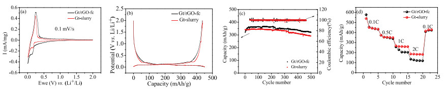
To investigate the energy storage application of the uniform Gt/rGO-fc membranes, the electrochemical performances are evaluated by half cells tests with Li foil as the counter electrode. For comparison, the conventional Gt-slurry are also tested under the same condition. In order to study their electrochemical behaviors, cyclic voltammetry (CV) of the two kinds of electrodes at a scanning rate of 0.1 mV/s in 0.01–2 V are evaluated. As shown in Fig. 3a, the Gt/rGO-fc and Gt-slurry electrodes have similar anodic and cathodic peaks at around ~0.25 V and ~0.1 V respectively, which are assigned to the deintercalation/intercalation potential of graphite materials.

|
Download:
|
| Fig. 3. Electrochemical characterizations of as-prepared Gt/rGO-fc membranes as electrodesand conventional graphite electrodes (Gt-slurry) in half cells. (a) Cyclic voltammograms at 0.1 mV/s. (b) Galvanostatic discharge/charge profiles at 0.1 C. (c) Specific capacity and coulombic efficiency at a rate of 1 C in 500 cycles. (d) Rate performance at rates of 0.1 C, 0.5 C, 1 C, 2 C and 0.1 C again. | |
In order to demonstrate the stability of the Gt/rGO-fc electrode, an extended lifecycle study is also conducted. The results show the curves in different cycles are almost identical, indicating the Li+ deintercalation/intercalation process is stable and reversible (Figs. S4a in Supporting information). In the typical galvanostatic discharge/charge profiles of the second cycle (Fig. 3b), the voltage plateaus between 0.01 V and 0.25 V corresponds to the lithiation/delithiation of graphite. The steady discharging specific gravimetric capacity of Gt/rGO-fc electrode at 0.1 C is found to be 450 mA h/g, which exceeds the theoretical capacity 372 mAh/g of graphite. This is because rGO sheets in the membrane, which account for 20% mass ratio, provide extra capacity in 0.01–2 V (Figs. S4b and c in Supporting information). The plateaus in both electrodes are stable and the discharge/charge capacity results are almost identical, indicating the Li+ removal/intercalation process is reversible. Fig. 3c shows the discharge capacity of the half cells in 500 cycles at 1 C (=372 mA/g). For the initial cycles of Gt/rGO-fc battery, the discharging capacity increases gradually, which may be ascribed to the gradual infiltration of the electrolyte in the electrode. The discharge capacity is up to 360 mAh/g after 25 cycles and has approximately 85% capacity retention after 500 cycles. The corresponding CE is almost 100%. For Gt-slurry electrode, the discharge capacity is 344 mAh/g, slightly lower than Gt/rGO-fc, while the CE is almost 100%.
The rate capability is also tested at different C-rates for five cycles at each C-rate in the voltage range of 0.01–2 V. The steady discharge capacities of Gt/rGO-fc electrodeat 0.1 C is 450 mAh/g. At higher C-rates of 0.5 C, 1 C and 2 C, the specific capacities are 364, 256, 133 mAh/g, respectively (Fig. 3d). Gt-slurry electrode shows a similar rate performance to Gt/rGO-fc. To better understand the electrochemical performances and further investigate the interfacial resistance of the two kinds of electrodes, electrochemical impedance spectroscopy tests are also carried out. As shown in Fig. S4d (Supporting information), the charge transfer resistance (Rct) of the semicircle of Gt/rGO-fc electrode and Gt-slurry electrode before bending are 67 Ω and 77 Ω, respectively, which implies the interfacial resistance of Gt/rGO-fc electrode is slightly lower than conventional one. We can conclude the performance Gt/rGO-fc membrane has a comparable performance as an electrode when compared with conventional one, indicating a promising application in the electrode of battery field.
To explore the university of our strategy, we have also synthesized the freestanding membranes with LiFePO4 (LFP, ~1 μm) and hard carbon (HC, ~5 μm) in the graphene foam, as the lithium battery cathodes and sodium battery anodes, respectively. The weight ratio of LiFePO4 and hard carbon are both 80%. Their microstructures and electrochemical performances are shown in Fig. 4 and Fig. S5 (Supporting information), respectively. In Fig. 4a, an oriented and uniform microstructure of GO layers and LFP particles are clearly showed. Fig. 4b shows the cyclic voltammetry curves of LFP/rGO-fc as cathodes at a scan rate of 0.1 mV/s. The oxidation peaks (around 3.5 V) and reduction peaks (around 3.3 V) in the CV plots confirmed the good reversibility of lithium extraction/insertion reactions. As seen in Fig. 4c, the LFP/rGO membrane has a typical charge-discharge curve of LFP with a long platform around 3.46 V and the membrane shows capacity of about 135 mAh/g at 0.2 C, similar to that of conventional LFP-slurry reported before [26], which indicates the spaces between rGO layers and LFP is favorable for the diffusion of Li-ions. Thus, the LFP/rGO-fc membrane provides good electrochemical performances in the batteries. We can get the same results when assembling hard carbon in the graphene network for HC/rGO-fc membranes for anodes in sodium battery. They still have comparable electrochemical performances to conventional HC-slurry electrodes. Therefore, it indicates that the fabrication method for particles/rGO-fc composite membranes is universal.

|
Download:
|
| Fig. 4. (a) SEM images of the cross section of lithium iron phosphate (LFP)/rGO-fc membranes. (b) Cyclic voltammograms at 0.1 mV/s of as-prepared LFP/rGO-fc membranes as electrodes in half cells. (c) Galvanostatic discharge/charge profiles at 0.2 C. (d) Specific capacity and coulombic efficiency at a rate of 2 C in 500 cycles. | |
In summary, we have developed a facile strategy for the fabrication of freestanding membranes of commercial micrometer-sized active particles, including graphite, hard carbon and lithium iron phosphate. Thanks to their excellent mechanical properties, high conductivity and large specific surface area, graphene sheets proved to be competent for the backbones for such micrometer-sized active particles. As electrodes, the composite membranes are devoid of other polymer binders and conductive agents. Freeze casting plays an important role in the uniform attachment of the particles onto graphene network, avoiding the severe phase separation of the two colloids during the solvent removing process, whereas vacuum filtration and natural drying cause cracks, voids and particle aggregation in the dried films, which fails to obtain uniform integral membranes. The electrochemical performance of composite electrodes prepared by freeze casting can be well comparable to the conventional commercial electrode, promising for the real application of freestanding membranes of commercial micrometer-sized particles.
Appendix A. Supplementary dataSupplementary material related to this article can befound, in the online version, at doi:https://doi.org/10.1016/j.cclet.2019.03.041.
| [1] |
F. Bonaccorso, L. Colombo, G. Yu, et al., Science 347 (2015) 1246501. DOI:10.1126/science.1246501 |
| [2] |
H.P. Boehm, Angew. Chem. Int. Ed. 49 (2010) 9332-9335. DOI:10.1002/anie.201004096 |
| [3] |
D. Li, M.B. Müller, S. Gilje, R.B. Kaner, G.G. Wallace, Nat. Nanotechnol. 3 (2008) 101. DOI:10.1038/nnano.2007.451 |
| [4] |
B. Qiu, M. Xing, J. Zhang, J. Am. Chem. Soc. 136 (2014) 5852-5855. DOI:10.1021/ja500873u |
| [5] |
C. Han, Z. Tian, H. Dou, X. Wang, X. Yang, Chin. Chem. Lett. 29 (2018) 606-611. DOI:10.1016/j.cclet.2018.01.017 |
| [6] |
C.K. Chua, M. Pumera, Chem. Soc. Rev. 43 (2014) 291-312. DOI:10.1039/C3CS60303B |
| [7] |
C. Cheng, D. Li, Adv. Mater. 25 (2013) 13-30. DOI:10.1002/adma.201203567 |
| [8] |
B. Xu, H. Wang, Q. Zhu, et al., Energy Storage Mater. 12 (2018) 128-136. DOI:10.1016/j.ensm.2017.12.006 |
| [9] |
Y. Zhou, R. Zhang, J. Wang, et al., ACS Appl. Energy Mater. 1 (2018) 2378-2384. DOI:10.1021/acsaem.8b00564 |
| [10] |
H.P. Cong, X.C. Ren, P. Wang, S.H. Yu, ACS Nano 6 (2012) 2693-2703. DOI:10.1021/nn300082k |
| [11] |
D. Yan, L. Qiu, Y. Wang, et al., Chin. Chem. Lett. 29 (2018) 922-926. DOI:10.1016/j.cclet.2017.09.066 |
| [12] |
M. Lotya, Y. Hernandez, P.J. King, et al., J. Am. Chem. Soc. 131 (2009) 3611-3620. DOI:10.1021/ja807449u |
| [13] |
M. Zhang, X. Yu, H. Ma, et al., Energy Environ. Sci. 11 (2018) 559-565. DOI:10.1039/C7EE03349D |
| [14] |
J. Kim, L.J. Cote, F. Kim, et al., J. Am. Chem. Soc. 132 (2010) 8180-8186. DOI:10.1021/ja102777p |
| [15] |
Q. Xu, J.K. Sun, Y.X. Yin, Y.G. Guo, Adv. Funct. Mater. 28 (2018) 1705235. DOI:10.1002/adfm.201705235 |
| [16] |
W. Gao, L.B. Alemany, L. Ci, P.M. Ajayan, Nat. Chem. 1 (2009) 403-408. DOI:10.1038/nchem.281 |
| [17] |
X. Zhou, Y.X. Yin, L.J. Wan, Y.G. Guo, Adv. Energy Mater. 2 (2012) 1086-1090. DOI:10.1002/aenm.201200158 |
| [18] |
Y. Yang, C. Chen, J. Hu, et al., Chin. Chem. Lett. 29 (2018) 1777-1780. DOI:10.1016/j.cclet.2018.08.013 |
| [19] |
J. Kim, L.J. Cote, J. Huang, Acc. Chem. Res. 45 (2012) 1356-1364. DOI:10.1021/ar300047s |
| [20] |
S.P. Koenig, N.G. Boddeti, M.L. Dunn, J.S. Bunch, Nat. Nanotechnol. 6 (2011) 543. DOI:10.1038/nnano.2011.123 |
| [21] |
F. Kim, L.J. Cote, J. Huang, Adv. Mater. 22 (2010) 1954-1958. DOI:10.1002/adma.200903932 |
| [22] |
Y. Shao, M.F. El-Kady, C.W. Lin, et al., Adv. Mater. 28 (2016) 6719-6726. DOI:10.1002/adma.201506157 |
| [23] |
Y. Xu, Z. Lin, X. Huang, et al., ACS Nano 7 (2013) 4042-4049. DOI:10.1021/nn4000836 |
| [24] |
X.W. Yang, C. Cheng, Y.F. Wang, L. Qiu, D. Li, Science 341 (2013) 534-537. DOI:10.1126/science.1239089 |
| [25] |
F. Liu, S. Song, D. Xue, H. Zhang, Adv. Mater. 24 (2012) 1089-1094. DOI:10.1002/adma.201104691 |
| [26] |
T. Huo, N. Nie, Y. Liu, et al., Energy Fuels 30 (2019) 84-89. |