 2020, Vol. 31

b Hebei Key Laboratory of Boron Nitride Micro and Nano Materials, Hebei University of Technology, Tianjin 300130, China
Currently, the assemblies of nano-materials have attracted great attention due to their wide potential application in drug delivery [1], biosensing [2] and bioimaging [3, 4]. Many stimuli, such as temperature, pH and light, could exert influence on the assemblies of nano-materials. Carbon dioxide (CO2), a natural and green stimulus [5-7], has great potential in regulating the assemblies of nano-materials, including polymeric nano-materials [8-10], inorganic nano-materials [11, 12] and other assembly systems [13-16]. Moreover, CO2-controlled conjugated polymers based materials have been developed as well, recently [17, 18]. However, CO2 responsive materials still face some challenges. Generally, CO2-responsive is attributed to pH responsive behaviour, since the pH of aqueous solutions is controlled by the concentration of CO2 [19, 20]. The effectiveness of CO2responsive materials might be limited by pH range, usually from 4.0 to around 7.6. Moreover, CO2-responsive polymers can only exhibit their response at high CO2concentrations in aqueous solution, limiting their biological applications. Therefore, developing a new triggering approach to construct pH-independent CO2-responsive materials is highly desirable.
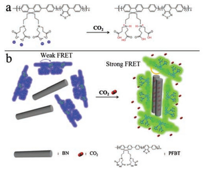
Due to the excellent fluorescence signal amplification, super light capturing ability and high fluorescence quantum yield, the assembly based on water-solubleconjugated polymers (WCPs) have been attracting enormous attentions in the field of biosensing [21, 22], cell imaging [23], protein detection [24] and disease treatment [25, 26]. CO2-responsive conjugated polymers are based on the reaction of CO2 with functional groups in the side chains. For example, Yoon and coworkers have constructed a CO2-responsive polydiacetylene-based polymer [27]. Kang et al. introduced a fluorophore to PDMAEMA to prepare a CO2-responsive polymer that exhibits a reversible color change by protonation or deprotonation of the aminemoiety in PDMAEMA through adding or removing CO2, switching the fluorescence emission intensity [28]. However, the gas capture ability of WCPs still cannot be competitive with that of multiple dimension materials, such as boron nitride (BN) [29], which exhibits excellent thermal stability [30], high oxidation stability [31] and super chemical inertness [32]. Moreover, the structure of multi-interspace existed on the surface of BNs shows excellent ability in absorbing small molecules including CO2, suggesting the BN to be potential platforms for CO2 capture [33]. Meanwhile, the excellent mechanical strength of BN can be used as a backbone of composites. M. Pulickel's group developed a stable porous boron nitride foam structure, which exhibited good mechanical properties, large surface area, and high porosity to improve the ability to adsorb CO2 [34]. Inspired by the above consideration, we construct here a CO2-controlled assembly of 2, 1, 3-benzothia-diazole units modified polyfluorene (PFBT) and BN fiber. The PFBT contains a side chain with two amino and four carboxylic acid groups in each repeat unit. There is no interaction between PFBT and BN fiber in aqueous solution. Upon bubbling CO2to the mixture of PFBT and BN fiber, the PFBT was adsorbed on the surface of BN fiber, showing an obvious variation of morphology. Moreover, the intramolecular energy transfer between fluorene structure and 2, 1, 3-benzothiadiazole occurs while bubbling CO2 to the assemblies. Therefore, our assemblies give an opportunity to investigate the variation process of nano-assemblies.
As illustrated in Scheme 1, the PFBT exhibits negative charges in aqueous solution due to the deprotonation of carboxylic acid functionalized side chain. The strong electrostatic repulsion prevents the aggregation of the polymer backbones, leading to random dispersion state and blue fluorescence under UV light. As the dispersion of BN in aqueous solution exhibits negative electricity as well, owing to the B-O-H and N-O-H generated on BN in water [35, 36], the powerful electrostatic repulsion between PFBT and BN keeps them separated. With the introduction of CO2, the protonation of carboxylate and amino groups in polymer PFBT decreases the electrostatic repulsion and enhances hydrophobic interactions between PFBT and BN, which promotes the interactions between the backbones of PFBT and BN, thus inducing shape-ordered aggregation. In addition, the intramolecular energy transfer from the polyfluorene to the 2, 1, 3-benzothiadiazole (BT) sites is also enhanced, causing color changing from blue to green. Therefore, the assembly of polymer PFBT with BN is controlled by carbon dioxide.

|
Download:
|
| Scheme 1. (a) Charge changes of PFBT upon bubbling with CO2 and (b) Schematic representation of PFBT and BN were assembled under the control of carbon dioxide. | |
Materials and Instruments: All organic solvents and chemicals were purchased from Tianjin Komiou Chemical Reagent Co., Ltd. and Shanghai Macklin BiochemicalCo., respectively, and used according to the specifications. CO2 (99.99% purity) was got from Tianjin Boliming Technology Co., Ltd. All solutions were prepared using Milli-Q water. The fluorescence spectra were assumed a Hitachi F-4600 fluorimeter furnished with a Xenon lamp excitation source. Dynamic light scattering (DLS) experiments and ζ potentials were accomplished with Nano-S90 (Malvern Instruments, UK). SEM images were measured by an EVO18 (ZEIZZ, GER) field-emission scanning electron microscope. AFM images were measured by a 5500 atomic force microscope (Agilent, USA) in a tapping mode. CO2-adsorption isotherms were obtained by Autosorb iQ-C-TCD (Quantachrome, USA). The BN aqueous solution was dealt by ultrasonic cleaning (SB-5200DT).
Acquisition of CO2 saturated ddH2O: To 50.0 mL of pre-cooling ddH2O was bubbled CO2 (99.99% purity) at a constant flow rate of 1.0 mL/min for more than 60 min, carried out this step and stockpiled the solution in ice for use. The concentration of CO2 enclosed in the CO2 saturated ddH2O is 76.05 mmol/L at 0 ℃, through referring to the Lange's Handbook of Chemistry.
Preparation of BN and PFBT aqueous solution: To 10 mg of the powder of BN was dispersed in 10 mL ultrapure water, and dealt by ultrasonic cleaning with a power of 20 W for about 5 min. PFBT was synthesized with reference to previous literature [37]. 1H NMR (400 MHz, D2O/Na2CO3): δ 7.70–7.28 (br, 8H), 3.51 (br, 2H), 3.0–2.8 (br, 13H), 2.3–2.6 (br, 8H), 2.2–2.0 (br, 18H), 1.0 (br, 4H), 0.90 (br, 4H).
Study for the CO2-controlled assembly of PFBT and BN: To a series of disparate concentrations of BN aqueous solutions and carbon dioxide saturated solutions were added PFBT, respectively. The total experimental volume was controlled at 500 μL and the final concentration of PFBT was always maintained at 10 μg/mL. The fluorescence spectra were obtained using 500 μL glass cuvettes at 4 ℃. The scan speed was 2400 nm/min. The purpose of controlling the temperature of the Hitachi F-4600 fluorometer could be achieved by using the Recirculating Chiller F-305 (BÜCHI).
Materials characterization: The N2 physisorption isotherms experiments measured by Autosorb iQ-C-TCD at -77 ℃. The pore size distribution was calculated by quenched solid density functional theory (QSDFT) [38, 39]. This method takes into account the effects of surface inhomogeneities and roughness on the geometric and chemically disordered micro and mesoporous structures, which apply to the current disordered PFBT/BN. BN and PFBT/BN aqueous solutions were prepared. PFBT/BN aqueous solution was bubbled with carbon dioxide gas near 30 min in a ice-bath and oscillated to dislodge redundant bubbles. Each of 2 μL BN, PFBT/BN and PFBT/BN with CO2 were taken out and orderly placed on the clean silicon wafers (for SEM) and the mica wafer (for AFM), and transferrd to the refrigerator for about 20 min and freeze-dried for about 2 h by lyophilizer.
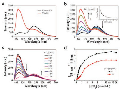
The conjugated polymer of PFBT and nanofiber of BN was synthesized according to previous literature [37]. The backbone of PFBT containing polyfluorene (PF) units as a donor and 2, 1, 3-benzothiadiazole (BT) units as receptor shows an obvious variation in fluorescence emission peak intensity under different concentration of CO2 as shown in Fig. S2 (Supporting information). In order to investigate the influence of BN nanofiber materials on the fluorescence spectrum of PFBT, we measured the fluorescence spectrum of PFBT and PFBT-BN mixture upon CO2bubbling, as shown in Fig. 1a.

|
Download:
|
| Fig. 1. Fluorescence emission spectra of PFBT in the presence of (a) CO2 without and with BN. [CO2] =1.5 mmol/L; (b) different concentrations of BN in aqueous solution with CO2. [CO2] =1.5 mmol/L. Inset: Plot of the fluorescence intensity ratio (I531 nm/I418 nm) of PFBT in the presence of different concentrations of BN in aqueous solution with CO2. [CO2] =1.5 mmol/L; (c) Different concentrations of CO2 with BN. [BN] =10.0 μg/mL. (d) Plot of the fluorescence intensity ratio (I531 nm/I418 nm) of PFBT in the presence of different concentrations of CO2 in aqueous solution without and with BN. [BN] =10.0 μg/mL, [PFBT] =10.0 μg/mL, the experimental temperature was 4 ℃. The excitation wavelength is 380 nm. | |
The fluorescence spectrum suggests that PFBT displays an absorption peak at 380 nm and two distinct emission peaks, corresponding to the polyfluorene (PF) units and the 2, 1, 3-benzothiadiazole (BT) units at 418 nm and 531 nm, respectively [37]. When adding BN nanofibre to PFBT aqueous solution, no obvious variation of emission spectrum for PFBT aqueous solution can be observed. However, adding the saturated aqueous solution of carbon dioxide to the PFBT aqueous solution causes decrease of emission peak intensity at 418 nm and increase of emission peak intensity at 531 nm [40]. Moreover, after bubbling CO2 to the PFBT and BN mixture, the emission spectra of the mixture show a similar variation trend compared with that of PFBT upon CO2 bubbling, while the emission peak intensity was stronger than that of PFBT upon CO2 bubbling. In order to investigate the influence of BN nanofibre on the fluorescence of PFBT, fluorescence spectra of BN nanofibre aqueous solution with a series of concentrations were measured. As indicated in Fig. 1a, in the presence of CO2, the fluorescence of PFBT with BN was restored comparing to the control without BN. By adding BN, the left emission peak (418 nm) of the polymer PFBT gradually increased. The plot of the fluorescence intensityratio (I531 nm/I418 nm) of PFBT under a constant CO2 concentration of 1.5 mmol/L was constantly reduced as a function of the BN concentration, indicating that the energy transfer from the fluorene to the BT moieties was decreased, which can be attributed to the capture of CO2 by BN. (Fig. 1b) The fluorescence of polymer PFBT does not change as a function of the BN concentration, as illustrated in Fig. S1 (Supporting information). When adding different concentrations of CO2 with BN concentration of 10.0 μg/mL, the left emission peak (418 nm) of the polymer PFBT was decreased by degrees and the right emission peak (531 nm) was improved (Fig. 1c).
Therefore, the fluorescence intensity ratio (I531 nm/I418 nm) of PFBT in the presence of increased CO2 concentrations was constantly improved and reached the platform period when the CO2 concentration reached 10 mmol/L. Fig. 1d, in the presence of CO2 with BN or without BN, compared the curve of fluorescence resonance energy transfer (FRET) ratio, indicating that BN could capture CO2, which prevents the formation of PFBT aggregates.
Many factors could influence the fluorescence intensity. As shown in the Fig. S3 (Supporting information), the different adding order of PFBT, BN and CO2 can result in different formation of aggregates, causing fluorescence quenching of polymer PFBT. When BN was added at last, the fluorescence intensity slightly increases (Fig. S3a) and no significant fluorescence difference can be observed between the systems with different adding order of CO2 and PFBT (Fig. S3b). However, the fluorescence of the assemblies significantly increases by adding samples with the order of BN/PFBT/CO2, which can be attributed to the preference of BN to capture CO2. Moreover, the other combination order shows little effect on the assembly, as well as little deference between the fluorescence intensity. (Fig. S3c)
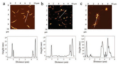
Furthermore, we performed dynamic light scattering (DLS) and the ζ potentialsexperiment in aqueous solution to verify the controlled carbon dioxide capture by the assembly of PFBT and BN. As shown in Fig. 2, the average hydrodynamic radiusand ζ potential of PFBT, BN and PFBT/BN is approximately 200 nm and -30 mV. The PFBT and BN were dispersed in aqueous solution due to the strong electrostatic repulsion between side chains of PFBT and BN. (Figs. 2a and c) However, after bubbling CO2, the ζ potential increased as the electrostatic repulsion between side chains of PFBT and BN was reduced, resulting to a larger average diameter. Notably, the significant increase in the average diameter of PFBT/BN suggests that CO2 is capable for effective control of the PFBT and BN assembly. (Figs. 2b and c) Scanning electron microscopy (SEM) was performed to obtain more evidence of the controlled assembly of PFBT and BN by CO2. As shown in Fig. 3, PFBT and BN were dispersed in the solution before bubbling CO2. However, the polymer of PFBT accumulated on the surface of BN upon CO2-bubbling, which is consistent with the DLS analysis, indicating the assemblies of PFBT and BN to be controlled by CO2. In addition, Atomic force microscopic (AFM) also showed similar results. As shown in Fig. 4, PFBT and BN were well-dispersed with the topographic height of approximately 15 nm. After bubbling CO2, the topographic height of the PFBT and BN assemblies were significantly enhanced to about 100 nm, demonstrating that PFBT and BN formed extraordinary aggregation at the existence of CO2. This result is consistent with the DLS analysis and morphological representation of SEM, indicating that CO2 is effective in controlling the assembly of PFBT and BN.

|
Download:
|
| Fig. 2. Size and ζ potentials analysis of assemblies. Size of PFBT, BN and PFBT/BN in aqueous solution without (a) and with (b) CO2. (c) ζ Potentials of PFBT, BN and PFBT/BN in aqueous solution without and with CO2. [PFBT] =10.0 μg/mL, [BN] =10.0 μg/mL, the experimental temperature was 4 ℃. | |

|
Download:
|
| Fig. 3. SEM images of (a) BN, (b) PFBT/BN and (c) PFBT/BN with CO2 in aqueous solution at room temperature. [PFBT] = 5.0 μg/mL, [BN] = 5.0 μg/mL. Bubbling CO2 at a constant flow rate of 1.0 mL/min for 30 min. | |

|
Download:
|
| Fig. 4. Atomic force microscopic (AFM) images of (a) BN, (b) PFBT/BN and (c) PFBT/BN with CO2. The line profiles of the aggregates are shown in the right. [PFBT] = 5.0 μg/mL, [BN] = 5.0 μg/mL. Bubbling CO2 at a constant flow rate of 1.0 mL/min for 30 min. | |
N2 isothermal adsorption method was used to study the characteristics of the pore structure of PFBT/BN assembly without or with CO2 [41]. As shown in Fig. 5, two samples showed typical IV isotherms, and no obvious hysteresis loops can be observed, indicating the existence of the microporous, mesoporous, and macroporous structure. There is a clear inflection point in the low relative pressure zone, which proves the existence of microporous structure. The porous structure of PFBT/BN is mainly attributed to BN nanofibers. The first inflection point of the N2adsorption-desorption isotherms of PFBT/BN with CO2 exhibits significant reduction than that without CO2, suggesting that the number of micropores in the assembly decreased by bubbling CO2. The curve of the relative high pressure zone shows a sharp rise, indicating the existence of macroporous structures. (Fig. 5a) The pore size distribution was calculated by quenched solid density functional theory (QSDFT) [38, 39], revealing a significant reduction of pore volume of PFBT/BN upon bubbling CO2. In addition, the assemblies exist mainly in the form of mesoporous rather than the microporous structure upon CO2-bubbling, demonstrating that PFBT and BN were clearly assembled under the existence of CO2.

|
Download:
|
| Fig. 5. (a) Nitrogen adsorption-desorption isotherms of PFBT/BN without and with CO2measured at -77 ℃, and (b) the pore size distribution plot of PFBT/BN without and with CO2using the quenched solid density functional theory. | |
In conclusion, carbon dioxide-controlled PFBT/BN assembly was demonstrated by taking advantage of CO2-responsive feature of the conjugated polymer of PFBT and the ability of capturing CO2 of BN. CO2 decreases the electrostatic repulsion between the functional group of PFBT and BN and increases hydrophobic interaction between PFBT and BN fiber, resulting in visible changes in fluorescence. Therefore, CO2 can be used as effective trigger for the assembly of PFBT and BN fibers. Moreover, PFBT enables the assembly with the signal amplification and light-harvesting properties. Furthermore, the polymers can simply assemble into supermolecular aggregates by non-covalent interactions without complicated synthesis procedures. Therefore, it is expected that carbon dioxide can be used as a new trigger to construct intelligent conjugated polymer-based materials, offering fluorescence monitoring strategy for carbon dioxide capture.
AcknowledgmentsThis work was supported by the National Natural Science Foundation of China (Nos. 21574037, 21773054 and 51803046), the "100 Talents" Program of Hebei Province, China (No. E2014100004), the Natural Science Foundation of Hebei Province (No B2017202051), the Program for Top 100 Innovative Talents in Colleges and Universities of Hebei Province (No. SLRC2017028).
Appendix A. Supplementary dataSupplementary material related to this article can befound, in the online version, at doi:https://doi.org/10.1016/j.cclet.2019.03.037.
| [1] |
L. Qiu, L. Zhao, C. Xing, Y. Zhan, Chin. Chem. Lett. 29 (2018) 301-304. DOI:10.1016/j.cclet.2017.09.048 |
| [2] |
H. Yuan, C. Xing, H. An, et al., ACS Appl. Mater. Interfaces 6 (2014) 14790-14794. DOI:10.1021/am504729d |
| [3] |
X. Feng, F. Lv, L. Liu, et al., ACS Appl. Mater. Interfaces 2 (2010) 2429-2435. DOI:10.1021/am100435k |
| [4] |
H.D. Cui, D.H. Hu, J.N. Zhang, et al., Chin. Chem. Lett. 28 (2017) 1391-1398. DOI:10.1016/j.cclet.2016.12.038 |
| [5] |
Q. Yan, Y. Zhao, Chem. Commun. 50 (2014) 11631-11641. DOI:10.1039/C4CC03412K |
| [6] |
Q. Yan, R. Zhou, C. Fu, et al., Angew. Chem. Int. Ed. 50 (2011) 4923-4927. DOI:10.1002/anie.201100708 |
| [7] |
Q. Yan, J. Wang, Y. Yin, J. Yuan, Angew. Chem. Int. Ed. 52 (2013) 5070-5073. DOI:10.1002/anie.201300397 |
| [8] |
Q. Yan, Y. Zhao, J. Am. Chem. Soc. 135 (2013) 16300-16303. DOI:10.1021/ja408655n |
| [9] |
H. Che, M. Huo, L. Peng, et al., Angew. Chem. Int. Ed. 54 (2015) 8934-8938. DOI:10.1002/anie.201501034 |
| [10] |
J. Guo, N. Wang, J. Wu, et al., J. Mater. Chem. B 2 (2014) 437-442. DOI:10.1039/C3TB21264E |
| [11] |
J. Alauzun, E. Besson, A. Mehdi, C. Reyé, R.J.P. Corriu, Chem. Mater. 20 (2008) 503-513. DOI:10.1021/cm701946w |
| [12] |
H. Che, M. Huo, L. Peng, et al., Polym. Chem. 6 (2015) 2319-2326. DOI:10.1039/C4PY01800A |
| [13] |
H. Yuan, C. Xing, Y. Fan, et al., Macromol. Rapid Commun. 38 (2017) 1600726. DOI:10.1002/marc.201600726 |
| [14] |
K. Jie, Y. Zhou, Y. Yao, B. Shi, F. Huang, J. Am. Chem. Soc. 137 (2015) 10472-10475. DOI:10.1021/jacs.5b05960 |
| [15] |
M. Zeng, M. Huo, Y. Feng, J. Yuan, Macromol. Rapid Commun. 39 (2018) 1800291. DOI:10.1002/marc.201800291 |
| [16] |
A. Feng, C. Zhan, Q. Yan, B. Liu, J. Yuan, Chem. Commun. 50 (2014) 8958-8961. DOI:10.1039/C4CC03156C |
| [17] |
J. Tan, X. Zhang, D. Liu, et al., Macromol. Rapid Commun. 38 (2017) 1600508. DOI:10.1002/marc.201600508 |
| [18] |
H. Yuan, Y. Fan, C. Xing, et al., Anal. Chem. 88 (2016) 6593-6597. DOI:10.1021/acs.analchem.6b01489 |
| [19] |
Y.T. Shieh, F.Z. Hu, C.C. Cheng, ACS Appl. Nano Mater. 1 (2018) 384-393. DOI:10.1021/acsanm.7b00237 |
| [20] |
B.A. Abel, M.B. Sims, C.L. McCormick, Macromolecules 48 (2015) 5487-5495. DOI:10.1021/acs.macromol.5b01453 |
| [21] |
X. Feng, L. Liu, S. Wang, D. Zhu, Chem. Soc. Rev. 39 (2010) 2411-2419. DOI:10.1039/b909065g |
| [22] |
J. Xu, C. Xing, X.H. Bu, Chin. Chem. Lett. 29 (2018) 217-218. DOI:10.1016/j.cclet.2018.01.009 |
| [23] |
F. Peng, L. Qiu, R. Chai, et al., Macromol. Chem. Phys. 219 (2018) 1700440. DOI:10.1002/macp.201700440 |
| [24] |
R. Chai, C. Xing, J. Qi, et al., Adv. Funct. Mater. 26 (2016) 9026-9031. DOI:10.1002/adfm.201601621 |
| [25] |
C. Zhu, L. Liu, Q. Yang, F. Lv, S. Wang, Chem. Rev. 112 (2012) 4687-4735. DOI:10.1021/cr200263w |
| [26] |
S. Li, X. Wang, R. Hu, et al., Chem. Mater. 28 (2016) 8669-8675. DOI:10.1021/acs.chemmater.6b03738 |
| [27] |
Q. Xu, S. Lee, Y. Cho, et al., J. Am. Chem. Soc. 135 (2013) 17751-17754. DOI:10.1021/ja410557x |
| [28] |
L.Q. Xu, B. Zhang, M. Sun, et al., J. Mater. Chem. A 1 (2013) 1207-1212. DOI:10.1039/C2TA00482H |
| [29] |
H. Zeng, C. Zhi, Z. Zhang, et al., Nano Lett. 10 (2010) 5049-5055. DOI:10.1021/nl103251m |
| [30] |
T.L. Li, S.L.C. Hsu, J. Mater. Chem. B 114 (2010) 6825-6829. DOI:10.1021/jp101857w |
| [31] |
Y. Chen, J. Zou, S.J. Campbell, G. Le Caer, Appl. Phys. Lett. 84 (2004) 2430-2432. DOI:10.1063/1.1667278 |
| [32] |
T. Terao, C. Zhi, Y. Bando, et al., J. Mater. Chem. C 114 (2010) 4340-4344. DOI:10.1021/jp911431f |
| [33] |
J.F. Janik, W.C. Ackerman, R.T. Paine, et al., Langmuir 10 (1992) 514-518. |
| [34] |
P.S. Owuor, O.K. Park, C.F. Woellner, et al., ACS Nano 11 (2017) 8944-8952. DOI:10.1021/acsnano.7b03291 |
| [35] |
M.J. Crimp, D.A. Oppermann, K. Krehbiel, J. Mater. Sci. 34 (1999) 2621-2625. DOI:10.1023/A:1004656817379 |
| [36] |
I.M. Joni, R. Balgis, T. Ogi, T. Iwaki, K. Okuyama, Colloids Surf. A 388 (2011) 49-58. DOI:10.1016/j.colsurfa.2011.08.007 |
| [37] |
Y. Fan, C. Xing, H. Yuan, et al., ACS Appl. Mater. Interfaces 9 (2017) 20313-20317. DOI:10.1021/acsami.7b05410 |
| [38] |
Q. Weng, X. Wang, Y. Bando, D. Golberg, Adv. Energy Mater. 4 (2014) 1301525. DOI:10.1002/aenm.201301525 |
| [39] |
A.V. Neimark, Y. Lin, P.I. Ravikovitch, M. Thommes, Carbon 47 (2009) 1617-1628. DOI:10.1016/j.carbon.2009.01.050 |
| [40] |
F. Meng, C. Xing, H. Yuan, et al., Chem. -Asian. J. 12 (2017) 2962-2966. DOI:10.1002/asia.201701280 |
| [41] |
S. Marchesini, C.M. McGilvery, J. Bailey, C. Petit, ACS Nano 11 (2017) 10003-10011. DOI:10.1021/acsnano.7b04219 |