 2020, Vol. 31


b Key Laboratory of Marine Materials and Related Technologies, Zhejiang Key Laboratory of Marine Materials and Protective Technologies, Ningbo Institute of Materials Technology and Engineering, Chinese Academy of Sciences, Ningbo 315201, China;
c Center of Materials Science and Optoelectronics Engineering, University of Chinese Academy of Sciences, Beijing 100049, China;
d Department of Electrical and Electronic Engineering, Faculty of Science and Engineering, University of Nottingham Ningbo China, Ningbo 315100, China;
e Laser Research Institute, Shandong Academy of Sciences, Qingdao 226100, China
Along with the shrinking feature size and improving power density of electronic devices, the accompanying thermal management issue has become a focal point in microelectronics manufacturing [1-3]. Therefore, there has been a growing demand for improving the thermal conductivity of polymer-based composites, which have been widely utilized as electrical packaging materials in electrical, electronic and energy industries [4, 5]. In recent years, based on the ultra-high intrinsic thermal conductivity (3500–5300 W/mK) and large specific surface area(2630 m2/g) of graphene, plenty of attention has been focused on the development of graphene-based polymer composites with improved heat-conducting property [6, 7]. However, the conventional preparation technique, by a solution or melt-blending process to incorporate graphene into the polymer matrix, can only endow the composites with limited thermal conductivity of 4–6 W/mK (20–50 wt% graphene addition), due to the difficulty of graphene dispersion and strong interfacial phononscattering between graphene and polymer matrix [8, 9].
In recent years, three-dimensional graphene framework has been considered as promising filler for the development of thermally conductive polymer composites, due to the enabling to directly create an interconnected graphene structure as heat channels in the polymer matrix [10]. Current approaches for the fabrication of graphene framework can be mainly classified into two categories, including self-assembly method and template-synthesis method [11]. The former was carried out by self-assembly and reduction of graphene oxide in aqueous solution, followed by freeze-drying to obtain graphene framework [12, 13]. However, this self-assembled graphene framework usually has a low density of 5–10 mg/cm3, by which the amount of graphene allowed to add in the polymer matrixes is hardly to be over 2 wt%, limiting the thermal conductivity of composites below about 2.5 W/mK [12]. In contrast, based on the template-synthesis method through the chemical vapor deposition (CVD) growth of graphene on compressed nickel foam, a graphene framework with a higher density of 96 mg/cm3 has been reported. The corresponding polymer composite presents an in-plane thermal conductivity of 8.8 W/mK with 8.3 wt% graphene addition [14]. However, both the CVD and the subsequent nickel etching process are complex, expensive and tedious, resulting in a low throughput and exorbitant costs of the graphene framework [15]. Therefore, it remains a great challenge for current methods to obtain a graphene framework with a high density, while maintaining adequate throughput for the economic development of the thermally conductive polymer composites with a practical value in industrial application.
Vacuum filtration is a commonly used strategy to fabricate graphene-based materials, and the filtrated graphene papers with tens of microns thickness have been commercially produced for using as high-performance heat spreader in portable devices [16, 17]. However, the conventional filtration process by directly filtrating the graphene-water dispersion is not available to smoothly prepare a graphene framework with a thickness up to centimeter scale, due to the fact of sample cracking in the filtration as a result of the unmatched surface tension between graphene (46.7 mJ/m2) and water (72.75 mJ/m2) [18, 19]. Herein, to address this issue, in this work, we proposed a surfactant-assisted strategy, in which the surfactant was adopted to modulate the surface tension of the water close to that of the applied graphene sheets, followed by a conventional filtration process to fabricate graphene framework. As a result, a graphene framework with a thickness up to 3 cm and an optimized density of 120–150 mg/cm3 was successfully prepared. After embedding into epoxy with the graphene addition of 13.6 wt%, the framework endows the composite with a high in-plane thermal conductivity of 12.4 W/mK, which is equivalent to a dramatic enhancement of ≈ 64 times compared to that of neat epoxy. Besides, compared to the template-synthesis method, our proposed strategy is simple and compatible with the conventional filtration process, presenting an economic feasibility for the high-throughput fabrication of graphene framework for putting into practical use.
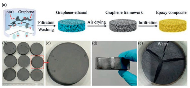
Fig. 1a is the schematic diagram of the fabrication process of our graphene framework/epoxy composites, including the surfactant-assisted filtration process to assemble graphene sheets into graphene framework, and a subsequent infiltration of epoxy to obtain the composite. In this work, sodium deoxycholate (SDC), a kind of anionic surfactant, was employed to modulate the surface tension of the water, and an optimized surface tension of 36–40 N/m can be obtained at the SDC concentration of 2 mg/mL in the water. Then, the graphene sheets (20 g) were dispersed in the surfactant-water solution (2000 mL) to obtain a stable graphene dispersion, which was then carried out a filtration process for the assembly of the graphene sheets, followed by an ethanol washing step to remove the SDC. After the air-drying, we obtained some large-scale graphene frameworks with the diameter of 9 cm and thickness of 3 cm, as shown in Figs. 1b-d. For comparison, a control experiment by the direct filtration of the graphene-water dispersion was performed. As the results shown in Fig. 1e, without the assistance of SDC, an apparent sample cracking in the filtration process can be observed, suggesting the superiority of our proposed surfactant-assisted strategy in fabricating graphene framework. The graphene framework/polymer composite was prepared by the infiltration of epoxy into the graphene framework. Initially, Nd(Ⅲ)acac was added into epoxy resin (6105) and stirred at 80 ℃ for 2 h to obtain a homogeneous solution, which was mixed with curing agent (MHHPA) with the weight ratio of 100:95 to obtain the epoxy precursor. The graphene framework was then immersed into the epoxy precursor solution for 1 h under vacuum to penetrate epoxy and remove the air bubbles, followed by curing at 165 ℃ for 14 h to obtain the composite.

|
Download:
|
| Fig. 1. (a) Schematic of the fabrication process of the graphene framework/epoxy composite. The photographs of the graphene framework prepared by (b–d) our proposed surfactant-assisted fabrication method and (e) the direct filtration of graphene/water dispersions. | |
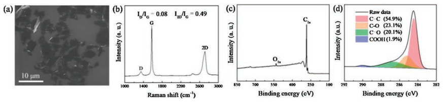
The properties of graphene-based materials have a close correlation with the intrinsic characteristic of the applied graphene sheets, including the size distribution, defects and the chemical composition, thus, some fundamental analyses on graphene sheets used in this study were carried out. As the SEM image shown in Fig. 2a, the laminar graphene sheets on the SiO2/Si substrate prepared by spin-coating method present a lateral size of 2–10 μm, with an average value of ≈ 5.4 μm. The Raman spectroscopy was executed to evaluate the quality of graphene sheets, as shown in Fig. 2b, in which three characteristic peaks of the graphene sheets can be found at 1350 cm-1 (D-band), 1580 cm-1 (G-band), 2700 cm-1 (2D-band), respectively [20, 21]. The calculated intensity ratio of 2D-band and G-band (I2D/IG = 0.49) and D-band and G-band (ID/IG = 0.08) indicates the multilayer nature of the graphene sheets with a few defects [22]. In order to investigate the chemical composition of graphene sheets, the sample was analyzed by X-ray photoelectron spectroscopy (XPS). In Fig. 2c, two peaks assigned to C 1s and O 1s can be observed and no other impurities can be found in XPS wide survey spectrum. The C 1s peak of can be further deconvoluted into four major components: C=C (54.9%, at 284.4 eV), C-O (23.1%, at 285.2 eV), C=O (20.1%, at 286.6 eV) and COOH (1.9%, at 289.0 eV), respectively [23]. The higher C=C content of 54.9% indicates a better quality of the graphene sheets employed in this study compared to that of reduced graphene oxide [24, 25].

|
Download:
|
| Fig. 2. (a) SEM image, (b) Raman spectrum, (c) XPS survey spectrum and (d) high-resolution XPS C 1s spectrum of graphene sheets. | |
The morphology of graphene framework was investigated by SEM analysis and shown in Fig. 3a, which presents an interconnected graphene structure in the framework with the density of 120–150 mg/cm3. In the high-resolution SEM image (Fig. 3b), an anisotropic arrangement of graphene sheets between parallel and perpendicular directions can be observed, in agreement with the reported graphene framework prepared via filtration [9, 26]. In Fig. 3c, the XRD pattern of graphene framework, which exhibits a smaller full width at half maximum value of the peak at 2θ = 26.2° [27] compared to that of graphene sheets, also implies the horizontal arrangement of graphene sheets in graphene framework. In addition, note that the characteristic peak of SDC (at 2θ = 17.5° [28]) cannot be observed in the XRD pattern of graphene framework, suggesting the almost complete removal of the SDC after the post-treatment of ethanol washing. As a result, we obtained a relatively clean graphene framework composed of interconnected and horizontally oriented graphene sheets via our proposed surfactant-assisted fabrication process. The graphene framework/epoxy (GF/EP) composite was fabricated by the infiltration of epoxy into the as-prepared graphene framework. As shown in Figs. 3d and e, the characteristic structure of mass ratio of graphene in the composite was investigated by the TGA analysis on the GF/EP and the neat epoxy in nitrogen. As shown in Fig. 3f, compared to the complete decomposition of neat epoxy, GF/EP exhibits a residual weight of ≈ 13.6 wt% (at 700 ℃), which is equivalent to the graphene content in the GF/EP.

|
Download:
|
| Fig. 3. (a, b) Cross-sectional SEM images of graphene framework. (c) The comparison of XRD patterns between graphene sheets and graphene framework. (d, e) Cross-sectional SEM images and (f) TGA curve of GF/EP. | |
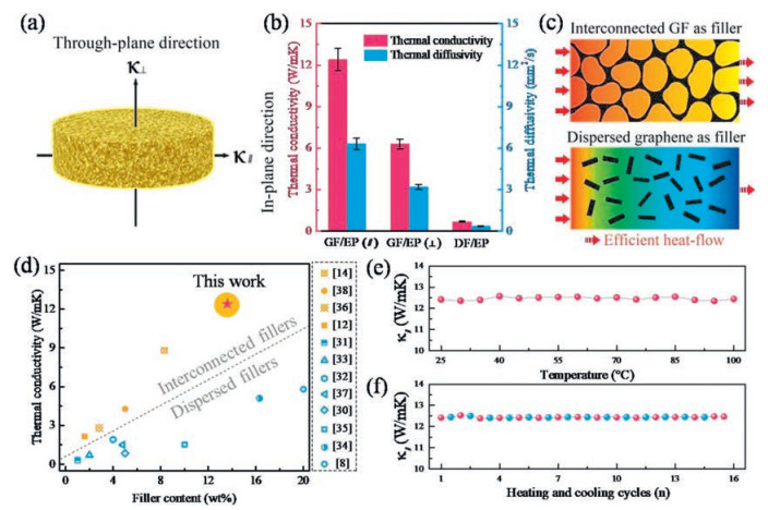
Based on the formation of interconnected graphene framework within the epoxy matrix, it can be anticipated that the GF/EP has a good heat conductionperformance. Accordingly, the thermal diffusivities (α) of GF/EP along in-plane and through-plane directions (Fig. 4a) were measured by the laser flash method. And the corresponding thermal conductivities (κ) were calculated by the equation: κ = α × ρ × Cp, where ρ is the average density (1.19 g/cm3) and Cp is the specific heat capacity (1.65 J g-1 K-1) of the measured samples [29]. As the results shown in Fig. 4b, at a graphene content of 13.6 wt%, GF/EP exhibits the in-plane (κ||) and through-plane thermal conductivity (κ⊥) of 12.4 and 6.3 W/mK, respectively, which are equivalent to ≈64 and ≈ 32 times higher compared to those of neat epoxy (0.19 W/mK). Besides, for comparison, the thermal property test on a control epoxy composite incorporated with the dispersed graphene as filler was carried out, in which the dispersed graphene/epoxy (DG/GP) was prepared by directly mixing the epoxy and graphene sheets with the same filler addition as GF/EP. Both the κ|| andκ⊥ of our GF/EP are one order of magnitude higher than the thermal conductivity of DF/GP (0.68 W/mK). It can be attributed to that the heat flow through an interconnected heat percolating channels of graphene-graphene provided by GF is more efficient than that dispersed graphene filler in epoxy matrix, as schematically illustrated in Fig. 4c. The comparison with previously reported graphene/polymer composites indicates that our GF/EP has superior thermal conductivity at the graphene loading less than 20 wt%, as shown in Fig. 4d [8, 12, 14, 30-38]. In addition, we further examined the reliability of GF/EP by investigating the environmental temperature dependence of κ||. As shown in Fig. 4e, κ|| of GF/EP is roughly constant with the temperature variation from 25 ℃ to 100 ℃, which is in agreement with the previous report of carbon-based polymer composites [39]. In Fig. 4f, the cyclic stability of κ|| was examined by the alternative test environment of GF/EP between 25 ℃ and 100 ℃ for 15 cycles. During the test, the average deviation of κ|| is less than 1% at both 25 ℃ and 100 ℃, indicating the preeminent thermal reliability and stability of GF/EP.

|
Download:
|
| Fig. 4. (a) Schematic illustration of the thermal conductivity of the composite along in-plane and through-plane direction. (b) The thermal conductivities and the diffusivities of GF/EP and DG/EP composites. (c) The scheme showing more efficient heat flow through an interconnected graphene filler compared to the dispersed graphene filler. (d) Comparison of thermal conductivity of our GF/EP with reported graphene/polymer composites. The variational in-plane thermal conductivity of the GF/EP (e) as a function of environmental temperature and (f) during the cyclic heating/cooling test. | |
In conclusion, we proposed a surfactant-assisted strategy to fabricate a 3 cm-thick graphene framework to address the sample cracking issue from the conventional filtration method when developing a sample with the thickness up to centimeter scale. The graphene framework with the density of 120–150 mg/cm3 was composed of interconnected and horizontally oriented graphene sheets. After embedding into epoxy, the graphene framework endows the composite with in-plane and through-plane thermal conductivity of 12.4 and 6.3 W/mK, respectively. The in-plane thermal conductivity achieved is equivalent to a dramatic enhancement of ≈ 64 times compared to that of neat epoxy, and much higher than that of most currently reported graphene framework/polymer composites based on self-assembly method. Based on this superior thermal conductivity enhancement for the composite and the simple operation process of our proposed method, our finding provide a possible solution in the development of the thermally conductive polymer composite to meet the ever-increasing thermal management requirement in industry.
AcknowledgmentsThe authors are grateful for the financial support by the National Key R & D Program of China (No. 2017YFB0406000), Scientific Instrument Developing Project of the Chinese Academy of Sciences (No. YZ201640), the Project of the Chinese Academy of Sciences (No. KFZD-SW-409), Science and Technology Major Project of Ningbo (Nos. 2016S1002 and 2016B10038), and International S & T Cooperation Program of Ningbo (No. 2017D10016) for financial support. We also thank the Chinese Academy of Sciences for Hundred Talents Program, Chinese Central Government for Thousand Young Talents Program, 3315 Program of Ningbo, and the Key Technology of Nuclear Energy (CAS Interdisciplinary Innovation Team, 2014).
| [1] |
L. Lv, W. Dai, A. Li, C.T. Lin, Polymers 10 (2018) 1201. DOI:10.3390/polym10111201 |
| [2] |
C. Yu, J. Zhang, Z. Li, et al., Compos. Part A Appl. Sci. Manuf. 98 (2017) 25-31. DOI:10.1016/j.compositesa.2017.03.012 |
| [3] |
C. Yu, W. Gong, W. Tian, et al., Compos. Sci. Technol. 160 (2018) 199-207. DOI:10.1016/j.compscitech.2018.03.028 |
| [4] |
F.E. Alam, W. Dai, M. Yang, et al., J. Mater. Chem. A Mater. Energy Sustain. 5 (2017) 6164-6169. DOI:10.1039/C7TA00750G |
| [5] |
J. Zhang, X. Wang, C. Yu, et al., Compos. Sci. Technol. 149 (2017) 41-47. DOI:10.1016/j.compscitech.2017.06.008 |
| [6] |
A.A. Balandin, S. Ghosh, W. Bao, et al., Nano Lett. 8 (2008) 902-907. DOI:10.1021/nl0731872 |
| [7] |
C. Zheng, X. Zhou, H. Cao, et al., J. Power Sources 258 (2014) 290-296. DOI:10.1016/j.jpowsour.2014.01.056 |
| [8] |
S. Ganguli, A.K. Roy, D.P. Anderson, Carbon 46 (2008) 806-817. DOI:10.1016/j.carbon.2008.02.008 |
| [9] |
H. Hou, W. Dai, Q. Yan, et al., J. Mater. Chem. A 6 (2018) 12091-12097. DOI:10.1039/C8TA03937B |
| [10] |
W. Dai, J. Yu, Y. Wang, et al., J. Mater. Chem. A 3 (2015) 4884-4891. DOI:10.1039/C4TA06417H |
| [11] |
M. Qin, Y. Xu, R. Cao, et al., Adv. Funct. Mater. 28 (2018) 1805053. DOI:10.1002/adfm.201805053 |
| [12] |
G. Lian, C.C. Tuan, L. Li, et al., Chem. Mater. 28 (2016) 6096-6104. DOI:10.1021/acs.chemmater.6b01595 |
| [13] |
Y.Q. He, N.N. Zhang, X.D. Wang, Chin. Chem. Lett. 22 (2011) 859-862. DOI:10.1016/j.cclet.2010.12.049 |
| [14] |
X. Shen, Z. Wang, Y. Wu, et al., Mater. Horiz. 5 (2018) 275-284. DOI:10.1039/C7MH00984D |
| [15] |
R. Zhang, R. Hu, X. Li, et al., Adv. Funct. Mater. 28 (2018) 1705879. DOI:10.1002/adfm.201705879 |
| [16] |
G. Xin, H. Sun, T. Hu, et al., Adv. Mater. 26 (2014) 4521-4526. DOI:10.1002/adma.201400951 |
| [17] |
B. Shen, W. Zhai, W. Zheng, Adv. Funct. Mater. 24 (2014) 4542-4548. DOI:10.1002/adfm.201400079 |
| [18] |
S. Wang, Y. Zhang, N. Abidi, L. Cabrales, Langmuir 25 (2009) 11078-11081. DOI:10.1021/la901402f |
| [19] |
N.B. Vargaftik, B.N. Volkov, L.D. Voljak, J. Phys. Chem. Ref. Data 12 (1983) 817-820. DOI:10.1063/1.555688 |
| [20] |
W. Dai, J. Yu, Z. Liu, et al., Compos. Part A-Appl. S. 76 (2015) 73-81. DOI:10.1016/j.compositesa.2015.05.017 |
| [21] |
Q.L. Meng, H. Liu, Z. Huang, et al., Chin. Chem. Lett. 29 (2018) 711-715. DOI:10.1016/j.cclet.2017.10.028 |
| [22] |
W. Dai, J. Yu, Y. Wang, et al., Macromol. Res. 22 (2014) 983-989. DOI:10.1007/s13233-014-2143-5 |
| [23] |
Z. Liu, D. Shen, J. Yu, et al., RSC Adv. 6 (2016) 22364-22369. DOI:10.1039/C5RA27223H |
| [24] |
K. Krishnamoorthy, M. Veerapandian, K. Yun, S.J. Kim, Carbon 53 (2013) 38-49. DOI:10.1016/j.carbon.2012.10.013 |
| [25] |
L. Li, X. Li, M. Du, et al., Chem. Mater. 28 (2016) 3360-3366. DOI:10.1021/acs.chemmater.6b00426 |
| [26] |
Q. Li, Y. Guo, W. Li, et al., Chem. Mater. 26 (2014) 4459-4465. DOI:10.1021/cm501473t |
| [27] |
H. Li, X.M. Xie, Chin. Chem. Lett. 29 (2018) 161-165. DOI:10.1016/j.cclet.2017.06.001 |
| [28] |
L. Wang, R. Liao, Z. Tang, et al., J. Phys. D: Appl. Phys. 44 (2011) 445302. DOI:10.1088/0022-3727/44/44/445302 |
| [29] |
X. Zeng, J. Sun, Y. Yao, et al., ACS Nano 11 (2017) 5167-5178. DOI:10.1021/acsnano.7b02359 |
| [30] |
S. Wang, M. Tambraparni, J. Qiu, et al., Macromolecules 42 (2009) 5251-5255. DOI:10.1021/ma900631c |
| [31] |
S.Y. Yang, W.N. Lin, Y.L. Huang, et al., Carbon 49 (2011) 793-803. DOI:10.1016/j.carbon.2010.10.014 |
| [32] |
C.C. Teng, C.C.M. Ma, C.H. Lu, et al., Carbon 49 (2011) 5107-5116. DOI:10.1016/j.carbon.2011.06.095 |
| [33] |
S. Chatterjee, F. Nafezarefi, N. Tai, et al., Carbon 50 (2012) 5380-5386. DOI:10.1016/j.carbon.2012.07.021 |
| [34] |
K.M. Shahil, A.A. Balandin, Nano Lett. 12 (2012) 861-867. DOI:10.1021/nl203906r |
| [35] |
S.H. Song, K.H. Park, B.H. Kim, et al., Adv. Mater. 25 (2013) 732-737. DOI:10.1002/adma.201202736 |
| [36] |
H. Ji, D.P. Sellan, M.T. Pettes, et al., Energ. Environ. Sci. 7 (2014) 1185-1192. DOI:10.1039/C3EE42573H |
| [37] |
X. Shen, Z. Wang, Y. Wu, et al., Nano Lett. 16 (2016) 3585-3593. DOI:10.1021/acs.nanolett.6b00722 |
| [38] |
J. Yang, X. Li, S. Han, et al., J. Mater. Chem. A 6 (2018) 5880-5886. DOI:10.1039/C8TA00078F |
| [39] |
I. Kholmanov, J. Kim, E. Ou, et al., ACS Nano 9 (2015) 11699-11707. DOI:10.1021/acsnano.5b02917 |