 2020, Vol. 31

b Yiyang Wanjingyuan Electronics Co., Ltd., Yiyang 413000, China;
c College of Traffic Engineering, Hunan University of Technology, Zhuzhou 412008, China;
d Key Laboratory of Materials Processing and Mold (Zhengzhou University), Ministry of Education, Zhengzhou University, Zhengzhou 450002, China;
e State Key Lab of Chemical Engineering, School of Chemical Engineering and Technology, Tianjin University, Tianjin 300072, China
Anode materials play crucial roles in determining the performance of rechargeable alkali metal-ion batteries (MIBs) [1-8]. Compared with other materials, hard carbon has attracted huge attention in MIBs due to its stably disordered structure, and relatively high reversible capacity [9-11]. In previous studies, there have been a large number of hard carbon reported as anode materials for lithium-ion batteries (LIBs) and sodium-ion batteries (SIBs) [12-15]. This will facilitate the anode development of emerging potassium-ion batteries (KIBs) for renewable energy and smart grids [16-20]. However, owing to the large ionic radius, hard carbon suffers from the low diffusion rate of K+ ion, which could bring the limited kinetics, and result in poor rate capability. For example, Ji's [18] group reported that hard carbon spheres suffered exhibited only 121 mA h/g at 1.4 A/g, although they could deliver a high reversible capacity of ~300 mA h/g at low current density. Heteroatom doping into hard carbon can bring defect sites that provide diffusion channel for K+ ions and enhance the rate performance of hard carbon. Xu and co-works prepared an N-doped carbon nanofiber paper by electrospinning method using the polymethylmethacrylate (PMMA) and polyacrylonitrile (PAN) as precursors [21]. The N-doped carbon nanofiber paper exhibited not only high reversible capacity and high cyclic stability, but also superior rate performance. Xiong's group reported the N/O co-doped porous hard carbon with a capacity of 118 mA h/g at 3 A/g [11]. Based on previous works, the doping of Sulfur heteroatoms can enhance the interlayer spacing of carbon crystal and bring some defect sites [22]. Thus, compared with pure carbon anode, S-doped carbon anodes shows higher potassium storage capacity and better capability [23].
In this work, the novel S-doped hard carbon (denoted as S−HC) was prepared through in-situ sulfuration process using resorcinol formaldehyde (RF) resin as the carbon source and commercial ZnO particles as hard template. Benefited from the rich defect sites caused by S doping, the S−HC showed a stable cycling life over 300 cycles at 1 A/g with little capacity decay. Moreover, a superior rate capability with a capacity of about 100 mA h/g at a large current density of 5 A/g was obtained.
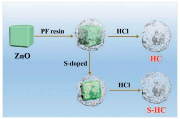
The synthesis process of porous S-doped hard carbon was described in Scheme 1. The synthesis method in detail was given as the Experimental Section in the Supporting information. As shown in Scheme 1, commercial ZnO particles in Fig. S1 (Supporting information) were encapsulated by PF resin to obtain porous carbon during the pyrolysis process [24]. Here, ZnO particles also acted as an activator that produces micropores. The S−HC could be obtained while treating ZnO@PF with sulfur powder together, with the partial sulfuration of ZnO into ZnS (Fig. S2 in Supporting information).

|
Download:
|
| Scheme 1. Schematic diagram of the synthesis of hard carbon and S-doped hard carbon. | |
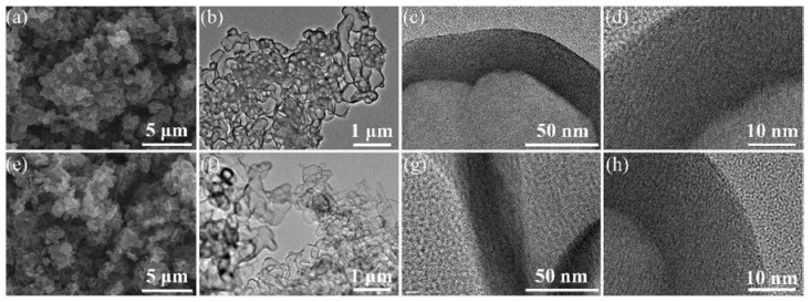
The morphology and structure of the S−HC and HC samples were examined by SEM and TEM techniques. The SEM image of the as-prepared S−HC in Fig. 1a reveals an interconnected architecture that was consisted of carbon particles. The S−HC sample in Fig. 1e shows the similar morphology. These interconnected architectures can play the role as 3D electronic transportation network that facilitates the infiltrating of the electrolyte for superior electrochemical performance. The low resolution TEM image of S−HC displayed in Fig. 1b reveals the porous structure with large inner void space. Fig. 1c shows that the thickness of the carbon shell is about 20–30 nm. In Fig. 1d, there are no lattice fringes observed, which suggests that this S−HC sample has the disordered structure with a low degree of crystallization. As shown in Figs. 1f-h, the HC also possesses the hollow structure with about 20 nm-thick hard carbon shells with poor crystallization.

|
Download:
|
| Fig. 1. (a) SEM image, (b) low magnification and (c, d) high TEM images of S-HC; (e) SEM image, (f) low magnification and (g, h) high TEM images of HC. | |
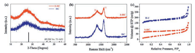
To have a better understanding on the structural characteristics of as-prepared HC and S−HC samples, XRD, Raman spectrum and BET characterizations were carried out. Fig. 2a shows the XRD patterns with the broad peaks located at 24°, which is ascribed to the (002) plane of graphite (JCPDS No. 75-1621). The low intensity and broad peak width suggest the disordered structure of hard carbon. Compared with the standard peak of (002) plane at 26.23°, the two peaks of HC and S−HC show a tiny shift to low degree range, indicating the expanded layer spacing of this plane, which is beneficial for potassium storage. To evaluate the defect level, Raman spectra were conducted and the results are shown in Fig. 2b. The strong D peak (1350 cm−1, defective and dangling edge carbon) and G peak (1595 cm−1, graphitic carbon) also indicate the disordered structure with low crystallinity, which is consistent with the TEM investigation [11, 21]. The intensity ratio between the D peak and G peak of HC and S−HC are 0.7 and 0.798, respectively. It reveals that the structure of S−HC is more disordered than that of HC due to the doping of S [25]. Fig. 2c exhibits the N2 adsorption and desorption isotherms. HC sample exhibits a type-Ⅳ adsorption/desorption hysteresis, indicating the mesoporous structure. Due to the hollow structure, HC has a large specific surface area of 231 m2/g. Moreover, S−HC has a relative lower specific surface area of 139 m2/g. As shown in Fig. S3 (Supporting information), due to the doping of S heteroatoms, the S−HC has a more complex microporous structure. Generally, micropores have the stronger adsorptive capacity than mesoporous. Thus, during the desorption process, the S−HC showed remarkable hysteresis. That why the two samples have different N2 adsorption and desorption isotherms.

|
Download:
|
| Fig. 2. Phase analysis of HC and S-HC. (a) XRD patterns, (b) Raman spectra, and (c) N2 adsorption and desorption isotherms. | |
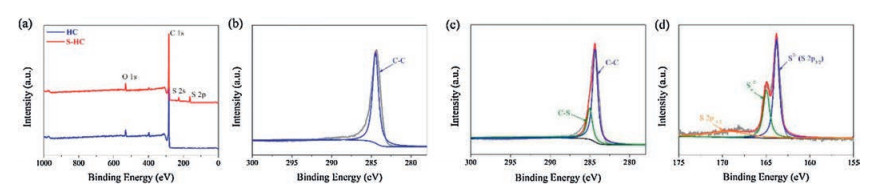
XPS was conducted to determine the elemental composition of as-prepared hard carbon samples, as shown in Fig. 3. The survey spectrum of HC in Fig. 3a shows a strong peak at 164 eV and a weak peak at 530 eV that are assigned to C 1s and O 1s, respectively [26]. It reveals that HC consists of a large amount of carbon and a little bit of oxygen. The survey spectrum of S—HC shows another two peaks of S 2s and S 2p [17, 27], indicating the successful S doping with an atomic content of 4.07%. Figs. 3b and c show the C 1s spectra of HC and S—HC, respectively. Owing to the high purity of carbon, the spectrum of HC can be fitted by the single peak located at 284.6 eV, assigned to C—C bond. On the contrary, that of S—HC can be divided into two peaks. One fitting peak belonged to C–S bond at 285.3 eV. The high-resolution S 2p spectrum of S—HC in Fig. 3d indicates there are two strong fitting peaks of S2− (163.8 eV) and polysulifide chain (SN2−, 164.9 eV) [28]. Besides, the peak at 168.1 eV can be assigned to the spin-orbit of S 2p1/2 [29]. It can be concluded that there exists quit a number of C–S bonds [25].

|
Download:
|
| Fig. 3. XPS spectra. (a) Survey spectra of HC and S-HC. High resolution C 1s spectra of (b) HC and (c) S-HC. (d) S 2p spectrum of S-HC. | |
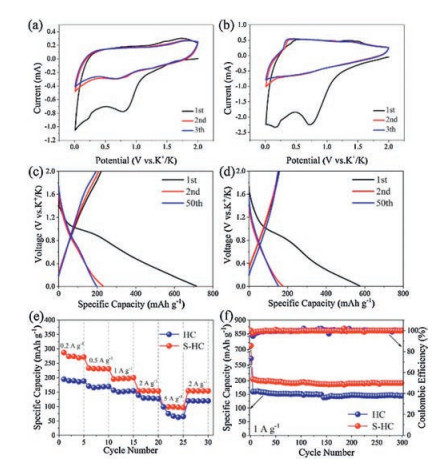
The potassium storage properties of S−HC and HC were analyzed in half cell versus K+/K. Fig. 4a shows the CV curves of S−HC tested at 0.1 mV/s. The CV of HC tested at the same scan rate is exhibited in Fig. 4b. Different form the CV of H−SC, after the first cycle, the reductive peak at about 0.6 V did not emerge, meaning the absence of electrochemical absorption caused by S heteroatoms. In Fig. 4c, during the first potassiation process, there exists a plateau at about 1 V corresponding to the irreversible formation of SEI film. This plateau does not emerge in the subsequent cycles, leading to the huge capacity loss between the first and second cycles. During the second cycle, it reveals a pair of discharge/charge plateaus at about 0.7 V and 1.6 V respectively, corresponding to the electrochemical adsorption/desorption of potassium ions on S defect sites. However, those two plateaus are tiny, suggesting that the potassiation/depotassiation processes are mainly controlled by capacitive electrochemical behavior at this current density of 1 A/g. The profiles of the second cycle and the fifty cycle overlap a lot, indicating the good cyclic stability of S−HC. On one hand, for HC anode, the high initial discharge capacity and the large capacity loss are also revealed for HC anode in Fig. 4d. On the other hand, due to the lack of S heteroatom, there is no plateau emerging in the subsequent cycles.

|
Download:
|
| Fig. 4. Potassium storage properties. CV curves at a scan rate of 0.1 mV/s in the different cycles of (a) S-HC, (b) HC. Charge/discharge profiles at 1 A/g for selected cycles of (c) S-HC and (d) HC. (e) Rate performance at various current densities and (f) comparison of cyclic stability of S-HC and HC electrodes. | |
The rate capabilities of S−HC and HC were evaluated at the current density ranging from 0.2 A/g to 5 A/g, as shown in Fig. 4e. S−HC delivered a high reversible capacity of about 270 mA h/g at 0.2 A/g. With the current density increasing, the capacities of 230, 196, 153, and 98 mA h/g were obtained at 0.5, 1, 2 and 5 A/g, respectively. When tested at 2 A/g once again, the reversible capacity recovered to 154 mA h/g. The HC only showed the relative low capacities of 189, 165, 151, 128 and 66 mA h/g at 0.2, 0.5, 1, 2 and 5 A/g. Besides, S−HC still delivered a high capacity of 191 mA h/g after 300 cycles at 1 A/g, whereas a low capacity of 145 mA h/g was obtained by HC at the same current density. Moreover, the electrochemical performance of S−HC is also comparable to other reported work, as shown in Table S1 (Supporting information). The doping of S heteroatom can bring rich defect sites, which play the dual role of activated adsorption sites and diffusion channel of K+ ions. The large void space can alleviate the volume change to make S−HC to obtain long cycle life. Thus, as displayed in Fig. 4f, S−HC electrode has the better rate capability and higher reversible capacity over long cycles, compared to HC anode.
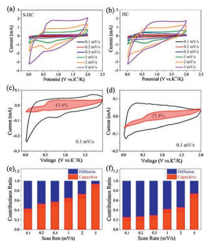
To study the kinetics for the potassium storage of as-prepared hard carbon samples, CV measurements were operated at different sweep rates from 0.2 mV/s to 5 mV/s. As shown in Fig. 5a, all the CV curves of S−HC show similar shape, suggesting the small polarization. The S-doping can enhance K+ ion diffusion rates in S−HC. This is the reason why S−HC shows the fast kinetics for potassium storage. For HC anode, the cathodic peaks in Fig. 5b gradually disappeared with the increasing of scan rate, meaning the worse polarization than S−HC. Generally, the current value can be divided into two different parts: the diffusion-controlled part (k1v) and the capacitance contributing part (k2v). Based on the following equation, the contribution ratio of each part can be calculated [30]:

|
(1) |

|
Download:
|
| Fig. 5. CV curves obtained at various scan rates from 0.1 mV/s to 5 mV/s of (a) S−HC and (b) HC. Separation of capacitive and diffusion currents of H-OS-C at 0.1 mV/s of (c) S−HC and (d) HC. Contribution ration of capacitive and diffusion parts at various sweep rates of (e) S−HC and (f) HC. | |
As can be seen from the integration of CV curve displayed in Fig. 5c, for S−HC, 42.3% of the total capacity at 0.1 mV/s was contributed from the capacitive part. However, although HC has a large specific surface area, the capacitive part only contributed 25.8% of the total capacity at the same sweeping rate due to the lack of S-defect sites, as shown in Fig. 5d. From Figs. 5e and f, with the sweeping rate increasing, the capacitance-controlled ratio also increased. It means that the fast kinetics is mainly caused by the capacitive behavior occurring on the surface of hard carbons.
In summary, we have prepared porous S−HC by a facile templated method. The as-prepared porous S−HC exhibited good electrochemical performance with cycling stability and high rate capability. Both porous structure and S doping of HC contributed to the enhancement of electrochemical performance. This work will give a guidance to explore the carbon anodes through structural design and composition adjustment.
Declaration of competing interestThe authors declare that there is no interest for this manuscript.
AcknowledgmentsThis work was supported by the National Natural Science Foundation of China (Nos. 21905086, 51971090), the Key Research and Development Program of Hunan Province of China (No. 2018GK2031) and the Natural Science Foundation of Hunan Province (No. 2017JJ1008).
Appendix A. Supplementary dataSupplementary material related to this article can be found, in the online version, at doi:https://doi.org/10.1016/j.cclet.2019.10.008.
| [1] |
M. Wu, W. Ni, J. Hu, J. Ma, Nano-Micro Lett. 11 (2019) 44. DOI:10.1007/s40820-019-0273-1 |
| [2] |
S. Qi, B. Xu, V.T. Tiong, J. Hu, J. Ma, Chem. Eng. J. 379 (2020) 122261. DOI:10.1016/j.cej.2019.122261 |
| [3] |
B. Xu, S. Qi, P. He, J. Ma, Chem-Asian J. 14 (2019) 2925-2937. DOI:10.1002/asia.201900784 |
| [4] |
X. Xie, M. Mao, S. Qi, J. Ma, CrystEngComm 21 (2019) 3755-3769. DOI:10.1039/C9CE00531E |
| [5] |
M. Wu, B. Xu, Y. Zhang, et al., Chem. Eng. J. 381 (2020) 122558. DOI:10.1016/j.cej.2019.122558 |
| [6] |
X. Zhang, X. Cheng, Q. Zhang, J. Energy Chem. 25 (2016) 967-984. DOI:10.1016/j.jechem.2016.11.003 |
| [7] |
M. Wu, J. Yang, D.H.L. Ng, J. Ma, Phys. Status Solidi-RRL 13 (2019) 1900329. DOI:10.1002/pssr.201900329 |
| [8] |
D. Wu, C. Wang, M. Wu, et al., J. Energy Chem. 43 (2020) 24-32. DOI:10.1016/j.jechem.2019.08.003 |
| [9] |
D. Qiu, T. Cao, J. Zhang, et al., J. Energy Chem. 31 (2019) 101-106. DOI:10.1016/j.jechem.2018.05.014 |
| [10] |
Z. Yang, H. Guo, F. Li, et al., J. Energy Chem 27 (2018) 1390-1396. DOI:10.1016/j.jechem.2018.01.013 |
| [11] |
J. Yang, Z. Ju, Y. Jiang, et al., Adv Mater. 30 (2018) 1700104. DOI:10.1002/adma.201700104 |
| [12] |
V. Velez, G. Ramos-Sánchez, B. Lopez, et al., Carbon 147 (2019) 214-226. DOI:10.1016/j.carbon.2019.02.083 |
| [13] |
R. Fu, Z. Chang, C. Shen, et al., Electrochim. Acta 260 (2018) 430-438. DOI:10.1016/j.electacta.2017.12.043 |
| [14] |
S. Komaba, W. Murata, T. Ishikawa, et al., Adv. Funct. Mater. 21 (2011) 3859-3867. DOI:10.1002/adfm.201100854 |
| [15] |
E. Irisarri, A. Ponrouch, M.R. Palacin, J. Electrochem. Soc. 162 (2015) A2476-A2482. DOI:10.1149/2.0091514jes |
| [16] |
X. He, J. Liao, Z. Tang, et al., J. Power Sources 396 (2018) 533-541. DOI:10.1016/j.jpowsour.2018.06.073 |
| [17] |
M. Chen, W. Wang, X. Liang, et al., Adv. Energy Mater. 8 (2018) 1800171. |
| [18] |
Z. Jian, S. Hwang, Z. Li, et al., Adv. Funct. Mater. 27 (2017) 1700324. DOI:10.1002/adfm.201700324 |
| [19] |
C. Chen, Z. Wang, B. Zhang, et al., Energy Stor. Mater. 8 (2017) 161-168. DOI:10.1016/j.ensm.2017.05.010 |
| [20] |
S.J.R. Prabakar, S.C. Han, C. Park, et al., J. Electrochem. Soc. 164 (2017) A2012-A2016. DOI:10.1149/2.1251709jes |
| [21] |
X. Zhao, P. Xiong, J. Meng, et al., J. Mater. Chem. A: Mater. Energy Sustain. 5 (2017) 19237-19244. DOI:10.1039/C7TA04264G |
| [22] |
J. Ding, H. Zhang, H. Zhou, et al., Adv. Mater. 31 (2019) 1900429. |
| [23] |
Y.P. Li, W.T. Zhong, C.H. Yang, et al., Chem. Eng. J. 358 (2019) 1147-1154. DOI:10.1016/j.cej.2018.10.135 |
| [24] |
S. Qi, X. Xie, X. Peng, et al., Phys. Status Solidi-RRL 13 (2019) 1900209. DOI:10.1002/pssr.201900209 |
| [25] |
C. Cui, H. Wang, M. Wang, et al., Small 15 (2019) 1902659. DOI:10.1002/smll.201902659 |
| [26] |
G. Zou, C. Wang, H. Hou, et al., Small 13 (2017) 1700762. DOI:10.1002/smll.201700762 |
| [27] |
D. Xu, C. Chen, J. Xie, et al., Adv. Energy Mater. 6 (2016) 1501929. |
| [28] |
S.Y. Lee, Y.C. Kang, Chem. Eur. J. 22 (2016) 2769-2774. DOI:10.1002/chem.201504579 |
| [29] |
B.H. Hou, Y.Y. Wang, J.Z. Guo, et al., Nanoscale 10 (2018) 9218-9225. DOI:10.1039/C7NR09674G |
| [30] |
H. Yang, R. Xu, Y. Yao, et al., Funct. Mater. 29 (2019) 1809195. DOI:10.1002/adfm.201809195 |