 2020, Vol. 31

b College of Power and Energy Engineering, Harbin Engineering University, Harbin 15001, China;
c College of Light Industry, Harbin University of Commerce, Harbin 15001, China;
d Department of Infection Diseases, General Hospital of the PLA Rocket Force, Beijing 10088, China
Microbial fuel cells (MFCs) are a recently promising technology with exoelectrogenic bacteria to convert organic matter into electricity for the production of energy [1, 2]. However, there is still a major problem makes adopting microbial fuel cell technology to the real applications quite difficult. The wastewater needs to be treated continuously and the energy which is produced by the MFC might not be consumed continuously. To match the production and demand of the electricity, storage of electricity would be necessary. Maybe electricity storage capacity is a better way to match the electricity storage production with the demand of electricity. Dewan and Beyenal [3] use MFC with external capacitor to store the energy. The experiment results showed that more electricity can be obtained with an external capacitor. Recently, Deeke and Sleutel [4] utilize an integrated system that contains internal capacitive material into the bioanode, leading to the better performance in terms of more charge stored during the charging and discharging experiment. And this new type of internal capacitive bioanode is no need for an additional space and electrolyte (comparing to the external capacitor). The bioanode modified with capacitive material has the capacitive behavior, which is equivalent to the biocapacitor. When the circuit is opened, microbes attached to the surface of the anode degrade organic matter to produce electrons, which are stored in the capacitive material on the surface of the anode. When electricity is needed, both the stored electrons and the generated electrons are released at the same time. It can not only overcome the mismatching of the production and demand of the electricity, but also provide large current and high power output in a short time. In addition, the specific capacitance of the bioanode is positively correlated to the power density of the MFC and is negatively correlated to the charge transfer resistance, which implied the capacitive behavior of the anode plays an important role on the MFC performance [4].
Thus, the suitable anode material is the key component in determining the production and storage of electricity. Desirable anode materials should meet some requirements such as high surface area and porosity, large capacitance, excellent electrical conductivity, good biocompatibility. There are three typical anode materials: carbon-based material, conducting polymer and transition metal oxide. Carbon-based material carbon nanotubes [5] have been the focus of interest due to their good conductivity, stable electrochemical behavior. Conducting polymer [6, 7] has been intensively studied as an electrode material for MFC due to low cost and large theoretical capacity. In the field of transition metal oxide, MnO2 [8-10] has attracted most attention because of its large theoretical specific capacitance and good biocompatibility. However, no single material was suitable for using as an internal capacitive anode (large capacitance, excellent electrical conductivity and good biocompatibility). So using the advantage of different anode material to composite is a good option to meet these conditions. He and Zheng [11] prepared polypyrrole-MnO2 composite as free-standing electrode as supercapacitors. Oliveira [12] also used CNT/MnO2/PPy as composites successfully applied in supercapacitors. Yuan and Deng [13] utilize MnO2/PPy/MnO2 composite decorated on a carbon cloth successfully improve the performance of MFCs. However, the traditional anode substrate, such as carbon felt, carbon cloth, have only small pore sizes. Microbes are inaccessible to the interior of these kind flat anodes. Recently, some studies [14] exploited porous sponge which as the anode substrate instead of traditional substrate. Because sponge offers a continuous 3D surface that is virtually free of interrupted junctions, it can enable useful functionalities that are difficult to obtain with paper or textile. Li and Yang [15] utilize sponge/carbon nanotube/polypyrrole/manganese dioxide (S/CNT/PPy/MnO2) composite as supercapacitor obtained high capacitance. Use this structure composite as capacitive bioanode in a MFC however has not been reported before.
Based on these aspects, a three-dimensional porous sponge/nitrogen-doped carbon nanotube/polyaniline/manganese dioxide (S/N-CNT/PANI/MnO2) composite has been developed as capacitive bioanode in the MFC in this paper. The capacitive bioanode integrating a 3D porous sponge coated N-CNT as a conductive skeleton, an intermediate PANI layer with better interface, and a manganese dioxide layer outside providing large capacitance and surface area. Nitrogen enhances the reactivity of CNTs providing the better interaction of nanotube surface with conducting polymer and metallic particles. This capacitive bioanode provide porous structures and functionalized surfaces that are favorable for bacterial attachment and extracellular electron transfer. We can use this MFC capacitive bioanode containing S/N-CNT/PANI/MnO2 composite for production and storage electricity simultaneously, when the electric applications do not need electricity, and release the two parts electrons (electronic production and storage) simultaneously when the electric applications need electricity.
Commercial polyurethane sponges tailored into the desired size of 20×20×3 mm3 were pretreated through ultrasound degreasing in absolute ethyl alcohol for 30-50 min and repeating for 3-5 times. The simple dipping-drying process is shown below: Tailored sponges were dipped into 1 g/L nitrogen-doped-carbon nanotube (N-CNT, 60-100 nm in diameter) suspension solution with absolute ethyl alcohol as the solvent, then taken out and dried at 60 ℃. The dipping-drying process was repeated for 10 times to obtain the sponge/nitrogen-doped carbon nanotubes (S/N-CNT) electrode.
The S/N-CNT electrode material was immersed into the pellucid solution of aniline (ANI) and concentrated sulfuric acid (ANI:H2SO4=1:3) mixture, and the mixed solution of aniline and ammonium persulfate (ANI:APS=1:1) was added dropwise into the above solution with continuous magnetic stirring for 6 h. The whole process was performed in the ice water bath. Afterwards, the electrode was taken out and was repeatedly washed until neutral. Finally, the S/N-CNT/PANI electrode was obtained through dried at 60 ℃ in the vacuum oven. The outer MnO2 layer was synthesized by a traditional hydrothermal treatment [13].
The morphologies and elemental compositions of electrodes were examined by scanning electron microscope (SEM, FEI QUANTA 200, US). The MFC polarization curve was obtained using a two-electrode system with 3D S/N-CNT/PANI/MnO2 bioanode serving as the working electrode and graphite rod cathode as the counter electrode, and was recorded by an electrochemical workstation (CHI 760C) with a scan rate of 5×10⁻⁴ V/s. The maximum power/current density was calculated by normalizing the anode surface area. The power densities P (mW/m2) were calculated using P=IV/A. All the other electrochemical measurements for the bio-activity were conducted in the nutrient buffer solution with the three-electrode electrochemical system: The prepared anodes were used as the working electrodes, graphite rods were used as the counter electrodes, and Ag/AgCl (saturated KCl) electrode as the reference electrode. The charging-discharging experiments were carried out in a voltage window between −0.5 V and 0.3 V under 10 mA/cm2. The chronoamperometric experiment polarized at −0.1V.
The MFC used in this study consisted of two polycarbonate compartments, each with a liquid volume of 100 mL. The modified carbon felt was used as the MFC anode. Five graphite rods were used as the MFC cathode. The anolyte was inoculated with effluent from another active MFC. The microbial fuel cells were operated under the feed-batch mode with an external resistance, and the anolyte was refreshed after the voltage was < 50 mV. The catholyte of the microbial fuel cell was 10 g/L potassium ferricyanide. The temperature of each microbial fuel cell was controlled at 25 ℃. A 40-channel voltage data recorder was used to get the voltage of MFC.
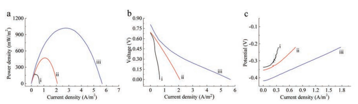
The performance of the MFCs equipped with the S/N-CNT, S/N-CNT/MnO2 and S/N-CNT/PANI/MnO2 are evaluated by measuring the power density curves (Fig. 1a), the polarization curves (Fig. 1b), and the individual potential of anodes curves (Fig. 1c), respectively. As shown in the Fig. 1a, the maximum power density of the MFCs with the S/N-CNT/PANI/MnO2 and S/N-CNT/MnO2 anodes reached to 1019.5 mW/m2 and 470.7 mW/m2, respectively. The maximum power densities reached were 5.8 times and 2.7 times higher than that of the S/N-CNT anode (176.6 mW/m2), respectively. Fig. 1b showed the polarization curve of MFCs. The open circuit voltage of the MFC with the S/N-CNT/PANI/MnO2 anode was about 0.807V, much larger than those of the MFCs with the S/N-CNT and S/N-CNT/MnO2 anodes. In here, all the conditions are prepared the same, except the anode material. So the higher open circuit voltage obtained by the MFC with S/N-CNT/PANI/MnO2 anode could be attributed to the performance of anode. As shown in the Fig. 1c, the anode potentials of S/N-CNT/PANI/MnO2 were more negative than that of S/N-CNT and S/N-CNT/MnO2 at the same current density, indicating that the performance of modified anode was obviously enhanced. It is believed that the reduction of activation losses, resulting from PANI modification, play a pivotal role in the reducing of anode over potential. The surface of anode modified with different materials has different physical and chemical properties, electrochemical behavior and extracellular electron transfer ability, thus showing different open-circuit voltage and polarization properties. Anode modification can accelerate the electron transfer from exoelectrogen to anode. The special structure of nitrogen doped carbon nanotubes made it have large specific surface area and good electrical conductivity and quasi Faraday effect. Moreover, nitrogen doped carbon nanotubes had many defects in ports and other places, making the chemical properties of nitrogen doped carbon nanotubes more active. Both of the MnO2 and PANI have large capacitance. Firstly, the anode modified by them, functions as a biocapacitor store the electron produced by the microbes when the circuit was in open condition. Thus these modified anodes showed different potential at open circuit. Because the cathode in cell circuit had very high positive potential, there exists a big driving force to make both of the MnO2 and PANI lose electrons and deliver them to anode and finally to the cathode through outer circuit when the circuit is in closed condition. From Fig. 1, the MFC equipped with the S/N-CNT/PANI/MnO2 anode has the best performance than other MFCs. The major mechanisms [16-17, 18] for improved performance in the MFC are: (ⅰ) N-CNT increased their storage capacity and offering the possibility of greater electrical conductivity as compared with undoped CNT; (ⅱ) The nitrogen-doped carbon nanotube and polyaniline composites displayed greater electrode specific capacitance, better mechanical integrity and higher electronic and ionic conductivity compared to pure nitrogen-doped CNT. The enhanced electrical conductivity of N-CNT-CL− doped PANI composite over neat PANI was explained by the dopant effect of N-CNT as suggested by the low CL/N ratio in the composite. It was proposed that the doping effect of N-CNT was due to a charge transfer from the quinoid unit of PANI to the N-CNT; (ⅲ) The addition of biocompatible interlayer PANI could facilitate the adapted bacteria enrichment and contribute significantly to provide more electrons. The results indicated that polyaniline could also accelerate the interaction between the inner-layer N-CNT and the outer-layer MnO2, which would then enhance the power generation of MFCs. The 3D porous sponge structure also provides open porous structures and functionalized surfaces that are favorable for bacterial attachment and extracellular electron transfer [19-21].

|
Download:
|
| Fig. 1. Performance of MFCs equipped with various anodes (ⅰ. S/N-CNT, ⅱ. S/N-CNT/MnO2, ⅲ. S/N-CNT/PANI/MnO2). (a) Power density curves of the MFCs with different anodes. (b) Polarization curves of the MFCs. (c) Individual potential of anodes in the MFCs. | |
Fig. S1 (Supporting information) shows the morphologies of the samples were examined by scanning electron microscopy (SEM). 3D porous sponge structure was shown in Fig. S1a. This kind of three-dimensionally structured materials have the feature of a distinct macroporous network with continuous macropores and high specific surface area, which can benefit the fast mass transport provide more contacts for the adhesion and growth of microbial. Fig. S1b shows the rough surface of S/N-CNT anode with the carbon nanotube diameter of around 60-100 nm. Fig. S1c is the enlarged SEM image of S/N-CNT/MnO2 anode. It can be clearly seen many very thin rods-like MnO2 heaped together scatteredly. The skeleton of the carbon nanotube can be fully covered by the rods-like MnO2, with almost no carbon nanotube exposed to the surface. Fig. S1d presents the SEM images of S/N-CNT/PANI/MnO2 anode, a similar rod-like MnO2 layer was observed on the outer-layer surfaces. From Fig. S1d, it can be seen that the MnO2 rod became thicker than that of S/N-CNT/MnO2 anode. But the PANI interlayer does not change the morphology of the MnO2. And the internal space was remained, thus suggesting that MnO2 grew mainly on the PANI surface rather than the nitrogen-doped carbon nanotube inner surface. Fig. S1e is the SEM images of S/N-CNT/PANI/MnO2 anode with biofilm growth time of ten days and shows a good growth condition of the bacillus as the main bacteria species. It can be clearly seen that the MnO2 layer was fully covered the bacteria, implying that 3D porous S/N-CNT/PANI/MnO2 anode benefits to the growth and adhesion of microbial. XRD was first employed to confirm the successful fabrication of the composite. Fig. 2 shows the XRD patterns of all three anodes. The S/N-CNT anode was observed a significant diffraction peak appears at the position of 2θ=25.9º which can be ascribed to the (022) plane of N-CNTs. In the pattern of S/N-CNT/MnO2 anode, three sharp peaks are observed at around 2θ = 28.7°, 37.3° and 56.7°, respectively. The three sharp peaks of the MnO2 at 28.7°, 37.3° and 56.7° correspond to the crystal of (110), (101) and (211) in β-MnO2 (JCPDS 24-0735), respectively. And there is no characteristic peaks of N-CNT appeared. This result indicates that MnO2 has been successfully covered on the N-CNT. For the S/N-CNT/PANI/MnO2 anode, the characteristic peak of PANI is observed at around 2θ=19.1°, all the other peaks could be indexed to the β-MnO2 (JCPDS 24-0735), indicating that PANI had been incorporated into the hybrid sample.

|
Download:
|
| Fig. 2. XRD Patterns of the S/N-CNT anode (ⅰ), S/N-CNT/MnO2 anode (ⅱ) and S/N-CNT/PANI/MnO2 composite anode (ⅲ). | |
The constant charge-discharge tests were performed to obtain the specific capacitance of S/N-CNT/PANI/MnO2 composite with biofilm, and the results are shown in Fig. 3. The specific capacitance could be calculated from the charge-discharge curve according to Eq. (1):

|
Download:
|
| Fig. 3. The charge-discharge curves of three anodes with biofilm in MFCs: ⅰ. S/N-CNT, ⅱ. S/N-CNT/MnO2, ⅲ. S/N-CNT/PANI/MnO2. Charging current density is 10 mA/cm2. | |

|
(1) |
where Icd is the charge-discharge current; t is the discharge time (s); Ucd is the potential window; and A is the projected anode surface area (cm2). The specific capacitance of 3D S/N-CNT/PANI/MnO2 composite is 138.3 F/cm2 at a current density of 10 mA/cm2, and is 2.1 times and 11.2 times as much as those of S/N-CNT/MnO2 anode (67.2 F/m2) and S/N-CNT anode (12.4 F/cm2), respectively. This performance improvement is due to the synergistic effect of the high pseudo-capacitance of the conformal PANI and MnO2 coating and the porous structure of N-CNT network. In the 3D S/N-CNT/PANI/MnO2 composite, the S/N-CNT provides a porous structure and a conductive network. The MnO2 layer is mainly responsible for pseudo reactions; the middle PANI layer and the N-CNT layer reduce the interface resistance, and improve the charge transfer.
During the chronoamperometric experiment, a period with open circuit condition (charging) was alternated with a period in which the anode potential was controlled at an anode potential of −0.1 V (discharging). The periods of chronoamperometric experiment were varied in different ratios between charging and discharging, according to the times given in Table S1 (Supporting information). Fig. S2 (Supporting information) shows the anode potential of different electrode varied from charging 10 min to 120 min. Fig. S2 shows that all of the anode potentials reduced with charging time range from 10 min to 120 min at open circuit operation condition. And compared with the S/N-CNT anode and S/N-CNT/MnO2 anode, the S/N-CNT/PANI/MnO2 anode potential decreased more with the increasing charging time in the open circuit condition. The largest anode potential of S/N-CNT/PANI/MnO2 anode is −0.383 V, which is much lower than those of S/N-CNT anode and S/N-CNT/MnO2 anode. So it was an indicative of the fact that the S/N-CNT/PANI/MnO2 capacitive bioanode had large specific capacitance and it had the ability to store more electrons. Fig. 4 gives the current density behaviors of all composite anodes with various charge-discharge periods. All of the curves exhibited a current peak at the beginning of the discharge, followed by a rapid current decay until the current approached a relatively constant value. A peak current far more greater that the steady state was shown for the S/N-CNT/PANI/MnO2 capacitive bioanode, suggesting that electrons collected from the metabolism at the open circuit state were released to the cathode as soon as the external circuit was connected. The peak current, stable current and cumulative charges are shown in Table S1. Comparing with S/N-CNT and S/N-CNT/MnO2 anodes, S/N-CNT/PANI/MnO2 capacitive bioanode possesses the greatest values (peak current, stable current) with various charge-discharge periods, suggesting a high stored charge on S/N-CNT/PANI/MnO2 composite anode. Each bioanode result in a similar increase in total charge from charging time 10 min to 60 min. After that the total charges do not keep increasing. And when the charge-discharge time is 60-20 min, the largest total charge value (10743.9 C/m2) of S/N-CNT/PANI/MnO2 bioanode was 1.71 and 3.23 times as much as those of S/N-CNT/MnO2 anode (6283.4 C/m2) and S/N-CNT anode (3323.4 C/m2), respectively; A higher peak current density of the S/N-CNT/PANI/MnO2 capacitive bioanode 18.32 mA/cm2 was 1.33 and 14.43 times as much as those of S/N-CNT/MnO2 anode (13.80 mA/cm2) and S/CNT anode (1.27 mA/cm2), respectively. The higher peak current and stable produced, the more charge stored during the open circuit period [22, 23]. It was clearly shown that the accumulate charges, peak, and stable current of the S/N-CNT/PANI/MnO2 capacitive bioanode were all higher than the bare anode, demonstrating that the synergistic effect of the high pseudo-capacitance of the conformal PANI and MnO2 coating and the porous structure of N-CNT network. In the 3D S/N-CNT/PANI/MnO2 composite, the S/N-CNTs provide a porous structure and a conductive network. This 3D porous structure can significantly increase the active surface area of electrode; provide high interfacial area, short ion diffusion path, and fast electrical pathways. PANI-MnO2 composite is favorable for the bigger contract area and growth of the attached microorganism and its porous structure favorable for the enhancement of mass transport. The addition of biocompatible interlayer PANI between two layers could facilitate the adapted bacteria enrichment and contribute significantly to improve the MFC capacitive performance.

|
Download:
|
| Fig. 4. The current density behaviors (−0.1 V) of three anodes (i. S/N-CNT, ii. S/N-CNT/MnO2, iii. S/N-CNT/PANI/MnO2) with various charge-discharge periods: (a) 10-20 min, (b) 20-20 min, (c) 40-20 min, (d) 60-20 min and (e) 120-20 min. | |
Overall, a three-dimensional macroporous composite of S/N-CNT/PANI/MnO2 was prepared used as the capacitive bioanode. The capacitive bioanode had successfully made MFC function as a biocapacitor, able to store electrons produced from the oxidation of organic substrate. And, the average power can be increased if the stored energy was dissipated in a short time. The S/N-CNT/PANI/MnO2 capacitive bioanode had significantly improved performance of energy storage and electricity generation. This can be attributed to the synergetic effect between carbon materials and pseudo capacitance material with excellent biocompatibility and good electrical conductivity. In addition, this macroporous S/N-CNT/PANI/MnO2 composite facilitates the growth of microbial, and accelerates the interactions among microbial, organic substrate and bioanode.
AcknowledgmentsThis work was supported by the National Natural Science Foundation of China (Nos. 21878060 and 21476053), China Scholarship Council (No. 201806685019).
Appendix A. Supplementary dataSupplementary materialrelatedtothisarticle can befound, inthe online version, at doi:https://doi.org/10.1016/j.cclet.2019.05.052.
| [1] |
J. Li, C. Liu, Q. Liao, X. Zhu, D. Ye, Int. J. Hydrogen Energy 38 (2013) 15723-15729. DOI:10.1016/j.ijhydene.2013.05.067 |
| [2] |
B.E. Logan, B. Hamelers, R. Rozendal, et al., Environ. Sci. Technol. 40 (2006) 5181-5192. DOI:10.1021/es0605016 |
| [3] |
A. Dewan, H. Beyenal, Z. Lewandowski, Environ. Sci. Technol. 43 (2009) 4600-4605. DOI:10.1021/es8037092 |
| [4] |
A. Deeke, T.H.J.A. Sleutels, H.V.M. Hamelers, C.J.N. Buisman, Environ. Sci. Technol. 46 (2012) 3554-3560. DOI:10.1021/es204126r |
| [5] |
A. Mehdinia, E. Ziaei, A. Jabbari, Electrochim. Acta 130 (2014) 512-518. DOI:10.1016/j.electacta.2014.03.011 |
| [6] |
J. Li, M. Zou, Y. Zhao, et al., Electrochim. Acta 111 (2013) 165-171. DOI:10.1016/j.electacta.2013.07.224 |
| [7] |
J. Luo, Q. Ma, H. Gu, Y. Zheng, X. Liu, Electrochim. Acta 173 (2015) 184-192. DOI:10.1016/j.electacta.2015.05.053 |
| [8] |
Y. Fu, J. Yu, Y. Zhang, Y. Meng, Appl. Surf. Sci. 317 (2014) 84-89. DOI:10.1016/j.apsusc.2014.08.044 |
| [9] |
X. Hu, Q. Liu, D. Ma, et al., Chin. Chem. Lett. 26 (2015) 1367-1370. DOI:10.1016/j.cclet.2015.06.003 |
| [10] |
Y. Chen, C. Chen, R. Lv, et al., Chin. Chem. Lett. 29 (2018) 616-619. DOI:10.1016/j.cclet.2017.12.028 |
| [11] |
M. He, Y. Zhang, Q. Du, Mater Lett. 104 (2013) 48-52. DOI:10.1016/j.matlet.2013.04.008 |
| [12] |
A.H.Pd. Oliveira, M.L.F. Nascimento, H.Pd. Oliveira, Mater Res. 19 (2016) 1080-1087. DOI:10.1590/1980-5373-MR-2016-0347 |
| [13] |
H. Yuan, L. Deng, Y. Chen, Y. Yuan, Electrochim. Acta 196 (2016) 280-285. DOI:10.1016/j.electacta.2016.02.183 |
| [14] |
X. Xie, M. Ye, L. Hu, et al., Energy Environ. Sci. 5 (2012) 5265-5270. DOI:10.1039/C1EE02122B |
| [15] |
P. Li, Y. Yang, E. Shi, et al., ACS Appl. Mater Interfaces 6 (2014) 5228-5234. DOI:10.1021/am500579c |
| [16] |
C. Oueiny, S. Berlioz, F. Perrin, Prog. Polym. Sci. 39 (2014) 707-748. DOI:10.1016/j.progpolymsci.2013.08.009 |
| [17] |
Z. Wang, Z. Zhang, S. Zhang, S. Chen, F. Zhao, J. Power Sources 287 (2015) 269-275. DOI:10.1016/j.jpowsour.2015.04.058 |
| [18] |
Q. Liu, Y. Zhou, S. Chen, et al., J. Power Sources 273 (2015) 1189-1193. DOI:10.1016/j.jpowsour.2014.09.102 |
| [19] |
Y. Yuan, S. Zhou, Y. Liu, J. Tang, Environ. Sci. Technol. 47 (2013) 14525-14532. DOI:10.1021/es404163g |
| [20] |
J. Tang, Y. Yuan, T. Liu, S. Zhou, J. Power Source 274 (2015) 170-176. DOI:10.1016/j.jpowsour.2014.10.035 |
| [21] |
J. Zheng, C. Cheng, J. Zhang, X. Wu, Int. J. Hydrogen Energy 41 (2016) 23156-23163. DOI:10.1016/j.ijhydene.2016.11.003 |
| [22] |
Z. Lv, D. Xie, F. Li, et al., J. Power Sources 246 (2014) 642-649. DOI:10.1016/j.jpowsour.2013.08.014 |
| [23] |
X. Peng, H. Yu, X. Wang, et al., Bioresour. Technol. 121 (2012) 450-453. DOI:10.1016/j.biortech.2012.06.021 |