 2019, Vol. 30


b CAS Key Lab of Low-Carbon Conversion Science and Engineering, Shanghai Advanced Research Institute, Chinese Academy of Sciences, Shanghai 201210, China
In recent years, the greenhouse effect caused by excessive carbon dioxide emissions has severely damaged the human environments. To address the issue, many porous materials such as carbon materials [1-3], metal-organic frameworks (MOFs) [4-6], and mesoporous silica nanoparticles (MSNs) have been widely used as the high-efficient adsorbents to capture CO2 gas. For example, Sun and co-authors [7] reported the synthesis of potassium tethered carbons, showing the enhanced affinity for CO2 adsorption under flue gas conditions. Significant efforts have been made towards MOFs and carbon-based materials, but they have inevitably own disadvantages including high cost, poor durability, and low chemical stability, etc. [8].
In contrast, MSNs possessing numerous merits of high surface area, tunablepore structure, aswell as easy functionalization have attracted a great deal of attention in catalysis, biomedicine [9-11], and adsorption [12], especially amine-functionalized MSNs. In the past two decades, MSNs with different structures have been extensively explored with the rapid development of sol-gel chemistry. Importantly, the particle size, morphology, and pore structure can be well tuned by rationally design the synthetic process [13]. As a result, diversified morphologies have been achieved such as hollow spheres [14-16], rattle-type [17], core-shell [18-20], crystal-like architectures [21], and Janus structures [22-25], etc. In these structures, hierarchical mesochannels from MSNs show unique advantages, which can notonlyfacilitate the substratemolecules easilyentering into the pore channels, but also offer more active sites for their subsequent adsorption [26, 27].
At present, the preparation and application of silica nanoparticles with hierarchical pore structures have become a hot topic. For instance, Teng et al. [28] adopted a two-step method to synthesize hierarchical silica nanospheres by using polystyrene as the hard template, then successively coating the silica and carbon layers. Shi et al. [29] also prepared the core-shell structured silica nanoparticles based on a two-step route. However, the above synthesis process mentioned is generally tedious, high cost, and not easy to operate. Therefore, it is still highly challenging to fabricate MSNs with desirable morphology and hierarchical pore structure by a facile assembly process.
In this work, we propose a scalable and simple strategy for the synthesis of MSNs by using tetraethylorthosilicate (TEOS) and N-[3-(trimethoxysilyl)propyl]ethylenediamine (TSD) as the co-silica sources and cetyltrimethylammonium bromide (CTAB) as the structure-directing agent. The as-made MSNs show a uniform morphology and a good dispersity. More interestingly, the MSNs product has a hierarchical pore structure, which mainly contains two kinds of pores centered in 3.99 nm and in the range of 6–20 nm, respectively. The control experiment reveals that the formation of the unique pore structure is mainly determined by the addition of TSD. Besides, after the modification of polyethyleneimine (PEI), the amine-functioned MSNs manifest the enhanced adsorption efficiency for CO2 capture.
Fig. 1a shows the typical SEM image of MSNs. The as-prepared MSNs have a spherical morphology and a uniform particle size with an average diameter of 230 nm, as measured by the particle size distribution (inset of Fig. 1a). Moreover, the surface of the spheres is relatively rough, as marked by red arrows, which suggests the presence of porous nanostructure in MSNs. Fig. 1b presents the typical TEM image of MSNs. Apart from the uniform morphology, the MSNs obtained show a good dispersity, which is further verified by the dynamic light scattering (DLS) result (Fig. S1 in Supporting information). Meanwhile, a weak contrast between dark and bright confirms the formation of abundant pores, in accordance with the SEM result. A closer observation from HRTEM image (Fig. 1c) reveals that the MSNs prepared possess the radially oriented mesochannels and hierarchical nanostructure. Seen from the magnified HRTEM image (inset of Fig. 1c), the pore structure is relatively ordered. Notably, the relatively large pores in MSNs can provide favorable conditions for the molecules to enter the inner channel during the adsorption process. STEM image and the corresponding elemental mapping (Fig. 1d) also indicate that the Si and O elements are uniformly distributed throughout the MSNs framework, while the N element is mainly derived from the TSD containing amino groups.

|
Download:
|
| Fig. 1. (a) SEM image (inset is the particle size distribution of MSNs), (b) TEM image, (c) HRTEM image (inset is the magnification of the white square area), and (d) STEM image of the typical MSNs product and the corresponding elemental mappings of Si, O, N. | |
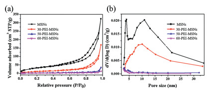
Fig. 2 illustrates the N2 adsorption-desorption isotherms and corresponding pore size distribution curves of MSNs products. As depicted in Fig. 2a, MSNs exhibit a typical type Ⅳ isotherm at the relatively high pressure, which is a basic characteristic of mesoporous material [30]. It is worth mentioning that MSNs has a sharp peak at 3.99 nm and a wide peak in the range of 6–20 nm, indicating the multilevel pore structure (Fig. 2b). The surface area and pore volume of MSNs is about 133 m2/g and 0.37 cm3/g, respectively. After modification by PEI, the surface area and pore volume are drastically reduced among these samples, and the order is 60-PEI-MSNs < 50-PEI-MSNs < 30-PEI-MSNs < MSNs (Table S1 in Supporting information). The reduction in pore volume is mainly due to the filling of PEI, whereas the mesoporous structure remains preserved even after functionalization.

|
Download:
|
| Fig. 2. N2 adsorption-desorption isotherms (a) and the corresponding pore size distribution plots of various MSNs products (b). | |
Interestingly, it is found that when the loading content of PEI is 30%, the peak at 3.99 nm disappears, and the average pore size increases to 10.06 nm. This phenomenon may be attributed to the reason that the PEI molecules easily diffuse into small pores of MSNs, thus causing the blockage of these small pores, whereas those large pores are well kept, as reported by previous work [31]. In this case, although the total pore volume decreases, the average pore size of modified MSNs increases (Fig. 2b). When more PEI molecules are loaded into the MSNs, these large pores are also fully blocked with the further reduction of the average pore size.
FT-IR spectra are used to identify the chemical groups in the different MSNs products. As shown in Fig. S2 (Supporting information), the distinct peaks at 775 cm-1 and 1100 cm-1 are generally ascribed to the characteristic of Si-O-Si groups. While the shoulder peak at 996 cm-1 confirms the existence of residual silanol groups, corresponding to Si-O-Si and Si-OH vibration [32]. After PEI modification, some new characteristic peaks are clearly observed in the range of 1300-1650 cm-1. Generally, the peaks at ~1650 cm-1 and ~1580 cm-1 are assigned to the -NH deformation of NH2+ and the formation NH3+, origining from the amine groups in PEI chain [33]. Other peaks at ~1310 and ~1400 cm-1 come from the skeletal vibration of carbamate (NCOO-) and stretching vibration of -NC group of carbamate, respectively [34]. In addition, the stretching vibration of C–H and bending vibration of -CH2 in PEI chain are described to the peak 2930-2850 cm-1 and 1470 cm-1, respectively. These results further verify that the formation of SiO2 and the successful modification of PEI onto MSNs.
Fig. 3a descripts the synthetic procedure of MSNs. The fabrication is based on a modified Stöber method [35], which is derived from the co-hydrolysis of TEOS and TSD. While the involvement of TSD in the synthesis leads to the difference degree condensation of silica species, thus resulting in the formation of MSNs with hierarchical pore structure. At the absence of TSD, the obtained silica nanoparticles have a spherical morphology with about 180 nm (Fig. S3 in Supporting information). Moreover, the pore structure is single, which is totally different with the typical MSNs. Therefore, the induced TSD guides the pore structure of MSNs. Along with the hydrothermal treatment and self-assembly process, MSNs with hierarchical pore structures is obtained after removing the template.

|
Download:
|
| Fig. 3. (a) Schematic illustration of the formation process for the typical MSNs. TEM images of MSNs products synthesized at different hydrothermal reaction time: (b) 1 h, (c) 6 h, (d) 24 h, and (e) 48 h. | |
To better probe the formation process of MSNs, the silica nanoparticles are collected at different hydrothermal reaction time. As shown in Figs. 3b and c, the porous structure has formed with the hydrothermal growth time of 1 h (Fig. 3b). After aged 6–12 h, the porous structure seems more obvious and extends into the inside of silica spheres (Figs. 3c and 1 b). Further increasing the reaction time to 24 h, the porous silica spheres almost turn to the hollow structure (Fig. 3d). While hydrothermal treatment for 48 h (Fig. 3e), the perfect hollow structure completely disappears. The product shows relatively disordered pore structure, which is composed of a lot of small silica nanoparticles. Based on the above observations, we tentatively propose the growth mechanism of MSNs in present system. When TEOS and TSD as the silica precursors are added to the ethanol aqueous solution, they are gradually hydrolyzed to produce some silica species, which are further assembled with CTAB micelles to form the silica spheres. Meanwhile, the different hydrolysis speed between TEOS and TSD results in the difference condensation degree, which becomes a key factor for the formation of MSNs. Previous work has demonstrated that the silicate/CTAB composites with low condensation degree are easily attacked by water molecules and tend to dissolved [36, 37]. When the as-prepared silica spheres suffer from the hydrothermal treatment, the outer layer with high condensation degree partially dissolves at the beginning of hydrothermal process. That leads to the generation of large pores on the surface of silica spheres. Then, these pores offer more chances for solvent molecules to freely enter the interior of silica spheres. Accompanied by more solvent molecules entering the interior, the silica core with low degree condensation begins to dissolve faster than outside, while the relatively robust outer layer is still maintained. Nonetheless, once the hydrothermal time is long enough, the interior can be fully dissolved and the external structure is also destroyed. On the other hand, the TSD dosage is also an important parameter, which greatly affects the final structure of products. When the low TSD/TEOS volume ratio of 0.1 is used, the product shows an imperfect structure (Fig. S4a in Supporting information). With further adding the TSD/TEOS volume ratio in the range of 0.2–0.4, the MSNs with hierarchical pore structures can be produced (Figs. S4b and c in Supporting information).
The hierarchical pore structure endows MSNs the potential application, which can be further employed as absorbents for CO2 capture after amino-functionalization [38]. Additionally, the absorption capacity is directly related to the surface density of amines ontoMSNs [39].Therefore, a series of MSNs products with different PEI loading amounts are prepared, which are then tested the CO2 uptakeat 75 ℃ in 15 vol% CO2 atmosphere. Fig. S5 (Supporting information) presents the CO2 capturing abilities of these materials. The results manifest that pristine MSNs have only the CO2 adsorption capacity of 25.6 mg/g at 75 ℃ in 15 vol% CO2 atmosphere, which is mainly ascribed to the physics adsorption process. However, the adsorption performances obviously improve after PEI modification, where 30-PEI-MSNs product shows a little improvement owing to the presence of a small amount of amine in MSNs, with CO2 adsorption of 46 mg/g. In this case, the adsorption includes physical adsorption and chemical adsorption processes owing to the interaction PEI with CO2. Impressively, the 50-PEI-MSNs product exhibits the maximum CO2 uptake of 80.5 mg/g, greatly higher than the pure MSNs. The big enhancement is mainly attributed to the fact that the50-PEI-MSNsnot only maintain the hierarchical porous structure but also possess more organic aminesin theproduct.Those ensure the efficient adsorption of CO2 molecules, since the chemical adsorption is dominant during the capture process. Then, the CO2 uptake tends to decrease with increasing the PEI loading to 60 wt%. That may because that the excessive PEImolecules existin the surfaceofMSNs, causing CO2 gasto be difficult to enter the inner channel of MSNs. Additionally, to better shown the interaction between PEI-MSNs and CO2, the in-situ infrared spectra are further provided in Fig. S6 (Supporting information). After adsorption CO2 onto the 50-PEI-MSNs, several absorption peaks corresponding to the bicarbonate are clearly seen at 1643 cm-1, 1556 cm-1 and 1380 cm-1 [40]. While the absorption peaks at 1479 cm-1 and 1320 cm-1 are generally ascribed to the characteristics of monodentate bicarbonate and monodentate carbonate, respectively. The results suggest the generation of carbonate and bicarbonate owing to the interaction between adsorbed CO2 and PEI.
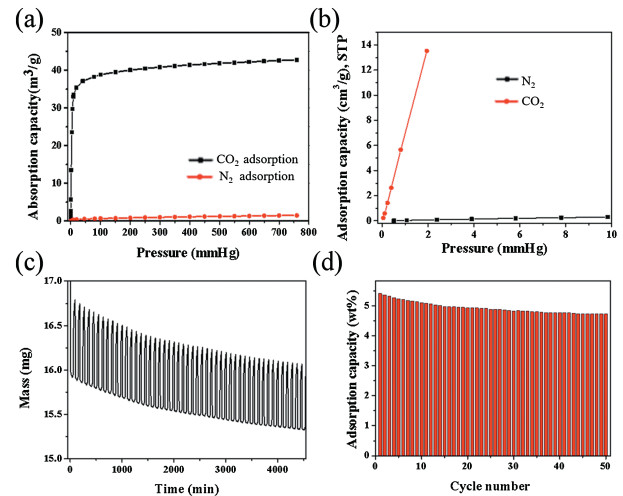
As a result, we choose the 50-PEI-MSNs as the optimal adsorbent for further study. Fig. 4a compares the CO2 and N2 adsorption isotherms collected at 25 ℃ on the 50-PEI-MSNs. The initial slope ratio of the adsorption isotherm at the low pressure is often used to evaluate the adsorption selectivity [41]. Fig. 4b shows the CO2 and N2 adsorption isotherm of 50-PEI-MSNs at less than 10 mmHg at 25 ℃. Accordingly, the CO2/N2 selectivity is calculated to about 223, meaning a high selectivity for CO2 adsorption, which is superior to previous report [42]. Furthermore, considering the N2 internal inertness, the porosity of the adsorbent is generally a more important parameter than the properties of the surface chemistry in terms of the adsorption of N2. The cycling stability of 50-PEI-MSNs is further investigated by using the TG analysis. A feeding of 15 vol% CO2 balanced with N2 is used, and the adsorption and desorption temperature are set to be 40 ℃ and 115 ℃, respectively. That is close to the actual situations of CO2 capture in the exhaust of coal-fired power plants.

|
Download:
|
| Fig. 4. (a) CO2 and N2 adsorption isotherm collected at 25 ℃. (b) Initial slope calculation for CO2 and N2 isotherms of 50-PEI-MSNs. CO2 adsorption/desorption cycles on 50-PEI-MSNs (15 vol% CO2, 40 ℃). (c) Weight gain and loss curve, and (d) the cycling stability of 50-PEI-MSNs. | |
Fig. 4c illustrates the weight gain and loss curve during adsorption/desorption cycles. A steep increasing of sample weight is clearly seen upon the exposure to CO2/N2, and adsorption capacity reaches as high as 90% within 4 min, showing a fast adsorption kinetics. Similarly, the desorption can be easily achieved by N2 purge at 115 ℃. Besides, although a slight decay is observed during the first 10 cycles (Fig. 4d), the CO2 adsorption capacity of 50-PEI-MSNs still retains at calcd. 4.73 wt% in the following 40 cycles, demonstrating a good cycling stability.
In summary, spherical MSNs have been designed through a facile self-assembly approach. Unique mesochannels and relatively high surface area of the as-made MSNs products provide their favorable conditions as the high-efficient adsorbents. As expected, the PEI-modified MSNs exhibit the good adsorption properties for CO2 capture. The results indicate that appropriate PEI loading amounts are benefit for the CO2 uptake, where the highest CO2 uptakes of 80.5 mg/g at 75 ℃ can be achieved in the 50-PEI-MSNs product. The high affinity and good selectivity of MSNs obtained in our study towards CO2 endow them as the potential candidate for CO2 capture under ambient conditions. Thus, we expect that the design of MSNs with hierarchical pore structures can open a new window for other applications such as in catalysis and biomedicine.
AcknowledgmentsWe are grateful for the support from the Shanghai Pujiang Program (No. 17PJD015) and Shuguang Program supported by Shanghai Education Development Foundation and Shanghai Municipal Education Commission (No. 18SG035).
Appendix A. Supplementary dataSupplementary material related to this article can befound, in the online version, at doi:https://doi.org/10.1016/j.cclet.2019.07.024.
| [1] |
M.G. Plaza, S. García, F. Rubiera, et al., Chem. Eng. J. 163 (2010) 41-47. DOI:10.1016/j.cej.2010.07.030 |
| [2] |
X.L. Zhu, P.Y. Wang, C. Peng, J. Yang, X.B. Yan, Chin. Chem. Lett. 25 (2014) 929-932. DOI:10.1016/j.cclet.2014.03.039 |
| [3] |
N.P. Wickramaratne, M. Jaroniec, ACS Appl. Mater. Interfaces 5 (2013) 1849-1855. DOI:10.1021/am400112m |
| [4] |
J. Li, Y. Ma, M.C. McCarthy, et al., Coord. Chem. Rev. 255 (2011) 1791-1823. DOI:10.1016/j.ccr.2011.02.012 |
| [5] |
K. Sumida, D.L. Rogow, J.A. Mason, et al., Chem. Rev. 112 (2011) 724-781. |
| [6] |
Y. Belmabkhout, V. Guillerm, M. Eddaoudi, Chem. Eng. J. 296 (2016) 386-397. DOI:10.1016/j.cej.2016.03.124 |
| [7] |
H.Y. Zhao, L. Shi, Z.Z. Zhang, et al., ACS Applied Mater. Interfaces 10 (2018) 3495-3505. DOI:10.1021/acsami.7b14418 |
| [8] |
F. Gao, J.B. Zhang, C.P. Li, T.R. Huo, X.H. Wei, Chin. Chem. Lett. 24 (2013) 249-252. DOI:10.1016/j.cclet.2013.01.043 |
| [9] |
H.C. Hu, J.J. Liu, J.Q. Yu, et al., Nanoscale 9 (2017) 4826-4834. DOI:10.1039/C7NR01047H |
| [10] |
Y. Chen, P.F. Xu, H.R. Chen, et al., Adv. Mater. 3 (2013) 100-3105. |
| [11] |
H.J. Zhang, H.J. Xu, M.H. Wu, et al., J. Mater. Chem. B:Mater. Biol. Med. 3 (2015) 6480-6489. DOI:10.1039/C5TB00634A |
| [12] |
H.J. Zhang, Z.Y. Li, P.P. Xu, R.F. Wu, Z. Jiao, Chem. Commun. (Camb.) 46 (2010) 6783-6785. DOI:10.1039/c0cc01673j |
| [13] |
F.Q. Tang, L.L. Li, D. Chen, Adv. Mater. 24 (2012) 1504-1534. DOI:10.1002/adma.201104763 |
| [14] |
Y. Chen, Q.S. Meng, M.Y. Wu, et al., J. Am. Chem. Soc. 136 (2014) 16326-16334. DOI:10.1021/ja508721y |
| [15] |
N. Ma, Y.Q. Deng, W.T. Liu, et al., Chem. Commun. (Camb.) 52 (2016) 3544-3547. DOI:10.1039/C5CC10106A |
| [16] |
H.N. Wang, M.T. Tang, L. Han, et al., J. Mater. Chem. A:Mater. Energy Sustain. 2 (2014) 19298-19307. DOI:10.1039/C4TA02899F |
| [17] |
X.W. Liu, G.R. Qian, Z. Jiao, M.H. Wu, H.J. Zhang, Chem.-Eur. J. 23 (2017) 8066-8072. DOI:10.1002/chem.201701140 |
| [18] |
X.W. Liu, Z. Jiao, T.T. Song, M.H. Wu, H.J. Zhang, J. Colloid Interface Sci. 490 (2017) 497-504. DOI:10.1016/j.jcis.2016.11.083 |
| [19] |
Z.G. Teng, S.J. Wang, X.D. Su, et al., Adv. Mater. 26 (2014) 3741-3747. DOI:10.1002/adma.201400136 |
| [20] |
H.B. Zou, R.W. Wang, X.X. Li, et al., J. Mater. Chem. A:Mater. Energy Sustain. 2 (2014) 12403-12412. DOI:10.1039/C4TA01943A |
| [21] |
J. Liu, H.Q. Yang, F. Kleitz, et al., Adv. Funct. Mater. 22 (2012) 591-599. DOI:10.1002/adfm.201101900 |
| [22] |
Z.G. Teng, X.D. Su, B.H. Lee, et al., Chem. Mater. 26 (2014) 5980-5987. DOI:10.1021/cm502777e |
| [23] |
J. Croissant, X. Cattoen, M. Wong, Man Chi, et al., Adv. Mater. 27 (2015) 145-149. DOI:10.1002/adma.201404226 |
| [24] |
X. Wang, B.Y. Guan, Y.P. He, et al., ChemNanoMat. 1 (2015) 562-566. DOI:10.1002/cnma.201500128 |
| [25] |
X. Wang, Y.P. He, C. Liu, et al., Nanoscale 8 (2016) 13581-13588. DOI:10.1039/C6NR03229J |
| [26] |
J.L. Pang, X.Y. Li, G.W. Zhou, B. Sun, Y.Q. Wei, RSC Adv. 5 (2015) 6599-6606. DOI:10.1039/C4RA12291G |
| [27] |
Z.K. Sun, Y.H. Deng, J. Wei, et al., Chem. Mater. 23 (2011) 2176-2184. DOI:10.1021/cm103704s |
| [28] |
Y.F. Teng, Y.Q. Jiang, Y.N. Zhang, X.Z. Xu, K.F. Lin, J. Porous Mater. 24 (2017) 241-248. DOI:10.1007/s10934-016-0257-1 |
| [29] |
L.J. Sun, D.G. Wang, Y. Chen, et al., Biomaterials 133 (2017) 219-228. DOI:10.1016/j.biomaterials.2017.04.028 |
| [30] |
M.F. De Lange, T.J. Vlugt, J. Gascon, F. Kapteijn, Microporous Mesoporous Mater. 200 (2014) 199-215. DOI:10.1016/j.micromeso.2014.08.048 |
| [31] |
K.M. Li, J.G. Jiang, S.C. Tian, F. Yan, X.J. Chen, J. Mater. Chem. A:Mater. Energy Sustain. 3 (2015) 2166-2175. DOI:10.1039/C4TA04275A |
| [32] |
H.Y. Geng, W.Y. Chen, P.Z. Xu, et al., Chem.-Eur. J. 23 (2017) 10878-10885. DOI:10.1002/chem.201701806 |
| [33] |
M.J. Almarri, M.M. Khader, M.M. Tawfik, G. Qi, E.P. Giannelis, Langmuir 31 (2015) 3569-3576. DOI:10.1021/acs.langmuir.5b00189 |
| [34] |
C.S. Srikanth, S.S.C. Chuang, J. Phys. Chem. C. 117 (2013) 9196-9025. |
| [35] |
W. Stöber, A. Fink, E. Bohn, J. Colloid Interface Sci. 26 (1968) 62-69. DOI:10.1016/0021-9797(68)90272-5 |
| [36] |
G.B. Alexander, W. Heston, R.K. Iler, J. Phys. Chem. 58 (1954) 453-455. DOI:10.1021/j150516a002 |
| [37] |
Z.G. Teng, X.D. Su, Y.Y. Zheng, et al., Chem. Mater. 25 (2012) 98-105. |
| [38] |
A.S. Bhown, B.C. Freeman, Environ. Sci. Technol. 45 (2011) 8624-8632. DOI:10.1021/es104291d |
| [39] |
E.S. Sanz-Pérez, A. Arencibia, G. Calleja, R. Sanz, Microporous Mesoporous Mater. 260 (2018) 234-244. |
| [40] |
A.C. Chang, S.S. Chuang, M. Gray, Y. Soong, Energy Fuel. 17 (2013) 468-473. |
| [41] |
R. Banerjee, H. Furukawa, D. Britt, et al., J. Am. Chem. Soc. 131 (2009) 3875-3877. DOI:10.1021/ja809459e |
| [42] |
P. Kumar, S. Kim, J. Ida, V.V. Guliants, Ind. Eng. Chem. Res. 47 (2008) 201-208. DOI:10.1021/ie070700d |