 2019, Vol. 30


b Shanghai Institute of Pollution Control and Ecological Security, Shanghai 200092, China;
c Fudan International School(FDIS), Shanghai 200433, China
In order to address the challenge of sustainable development, significant effort has been made for environmental problems through photocatalysis. The photocatalysis has been accepted as a convenient method and widely used in numerous applications such as solar energy conversion [1], electronic devices [2], water splitting [3], and pollutant decomposition [4-6] with simultaneous hydrogen production [7]. It is an efficient green sustainable method that employs free and infinite energy source on Earth [8, 9]. Photocatalytic materials have become important because they possess enhanced and exceptional physio-chemical properties compared to their corresponding analog. Generally, the photocatalyst performance highly depends on stability, chemical structure, specific surface parameters and charge separation [10, 11]. It is a fast-growing advanced oxidation process for toxic pollutant removal from the environment with their complete mineralization [12, 13]. Recently persistent organic pollutants such as perfluorooctanoic acid (PFOA) exposure through drinking water has become an emerging concern due to their tendency of accumulation in groundwater [14] and prevalent detected in living organism tissues especially in human beings [15, 16]. Various strategies have been employed for the synthesis of non-bioaccumulable alternatives to PFOA [17].
PFOA has been widely used in stain-resistant materials, nonstick cookware and other kind of products like fire-fighting materials, textiles, lubricants, and cosmetics [18]. About 90% of its contamination in the environment comes from its manufacturing and disposal sites, studies have shown that it causes cancer, reproductive and immune system problems [19, 20]. It is a highly stable, persistent compound due to the electron withdrawing properties of C—F bonds that make it difficult to be oxidized [21], although its natural degradation is not known. Numerous techniques have been employed for the degradation of PFOA such as electrochemical [22], adsorption [23], Fenton [24] and photocatalytic processes [25] while other studies on PFOA removal based on photochemical degradation by iron ions complex [26]. TiO2 is the most attractive photocatalyst due to its high degradation efficiency while hydroxyl radical (·OH) is generally the main active species in TiO2 system. TiO2 based photocatalytic degradation of PFOA proved ineffective but was only observed in acidic condition [27]. Therefore, there is an urgent need to find a suitable catalyst for its degradation.
Bismuth-based photocatalysts are a promising candidate due to their non-toxicity, high performance, stability and low cost [28, 29]. Bismuth oxychloride (BiOCl), a p-type semiconductor, exhibit good optical and well-defined morphological properties. It is a ternary layered oxide having a particular internal (Bi2O2) layer structure interleaved by van der Waals interactions between halogen (Cl) atoms [30]. This specific structure prevents the electron-holes pairs recombination and increases the redox potential [29]. Furthermore, bismuth phosphate (BiPO4) is an n-type semiconductor, non-metal oxyacid salt, and its effectiveness may be due to PO43– twisted tetrahedron structure which extends the charge carrier spell [31]. In fact, both catalysts are p- and n-type intrinsic semiconductor, the combination of these two catalysts with a proper position form a p-n type heterojunction [32]. Currently, we pay attention to BiOCl, BiPO4 and their heterojunction (BiPO4/BiOCl), although they have a wide band gap but, they have more positive valence band (VB) making them highly oxidative, and thus highly suitable photocatalysts for PFOA treatment [31]. The comparison of these bismuth-based catalysts with the most widely used TiO2 (P25) would be helpful to find the best photocatalyst for PFOA removal.
In this study, we explored the performance of the photocatalysts of BiOCl, BiPO4, and heterojunction of BiPO4/BiOCl, which were synthesized by a hydrothermal method. We compared systematically the photocatalytic activity of bismuth-based catalyst and TiO2 (P25) for the degradation of PFOA under 254 nm UV light. Further, the physiochemical and structural properties of the catalysts were studied by scanning electron microscopy (SEM), Raman spectroscopy, X-ray powder diffraction (XRD) and energy dispersive spectrometer (EDS).
The experimental section, including chemicals, photocatalysts preparation (synthesis of BiOCl, BiPO4, and BiPO4/BiOCl), characterization, photocatalytic degradation experiment, and analysis can be found in Supporting information.
The purity and crystal phase identification of synthesized catalysts were studied by X-Ray powder diffraction (XRD) (Fig. 1). The XRD patterns of BiOCl specifies the good crystallinity with properly indexed diffraction peaks to the tetragonal crystal structure (JCPDS file No. 06-0249) [21]. It can be observed that there are three strong peaks (001), (101) and (102) at 2θ values of 12.01°, 25.96° and 33.56°, respectively. BiPO4 sample exhibits the diffraction peaks that are well indexed to a monoclinic phase, which matches with the standard JCPDS file No. 80-209 [32]. The diffraction peaks at 2θ values of 19.01°, 21.33°, 27.14°, 29.07° and 31.17° coordinated well with the 011, 111, 200, 120, and 012 crystal planes of BiPO4 respectively [33]. Diffraction peaks of BiPO4/BiOCl exhibit the co-existence of BiOCl and BiPO4, which can be further supported by later study of SEM, EDS, RAMAN, and UV–vis diffraction reflection spectroscopy (UV–vis DRS). In the XRD pattern of TiO2 (P25), a chiefly anatase phase appears (JCPDS file No. 21-1272) and some rutile phase is identified (JCPDS file No. 21-1276). The diffraction peak at 110 confirms the co-existence of anatase and rutile phase in TiO2. No impurity peak was detected in all samples, indicating the high purity and the emergence of all strong peaks specifies the good crystallinity of all samples.

|
Download:
|
| Fig. 1. XRD patterns of BiOCl, BiPO4, BiPO4/BiOCl, and TiO2. | |
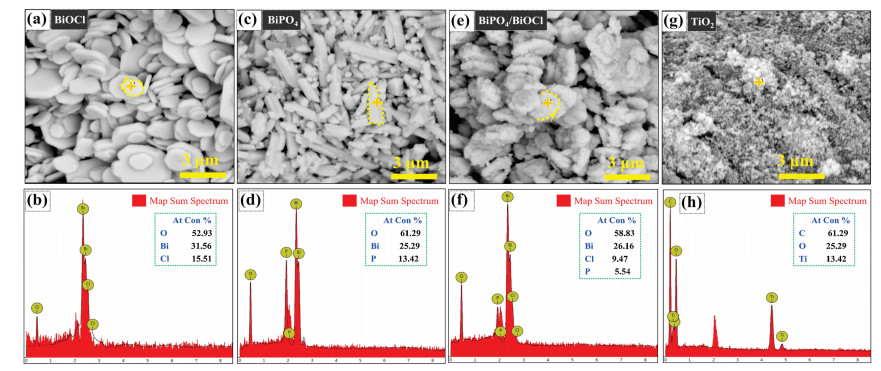
The structural morphology and elemental mapping of prepared photocatalysts BiOCl, BiPO4, BiPO4/BiOCl, and TiO2 (P25) are shown in Fig. 2. The BiOCl displays a huge quantity of assembled sheets with a smooth surface (Fig. 2a) and further confirmed that BiOCl was grown with (Bi2O2) layer structure enclosed by double halogen (Cl) atoms according to the literature [30]. Fig. 2b displays the leading signals of only Bi, O and Cl indicate the basic elements of BiOCl catalyst in the EDS spectrum, which means the product is pure [34]. BiPO4 depicting the rod-like elongated microcrystal structures with varying length ranges as spotted in Fig. 2c [35]. The EDS spectrum of BiPO4 (Fig. 2d) presents the signals of Bi, O and P offerings the main components of photocatalyst and no other element was detected [36]. Heterojunction of BiPO4/BiOCl possesses the morphological characteristic of both BiOCl and BiPO4. Simply there were many elongated rods and assembled sheets mixed together, representing the successful formation of heterojunction consistent with the SEM result of BiOCl and BiPO4 (Fig. 2e). It can be seen that (Fig. 2f) the heterojunction of BiPO4/BiOCl presents the dominant signals of Bi, O, Cl and P showing the mixed element composition of BiOCl and BiPO4. TiO2 (P25) sample shows the nanoporous morphology, as in Fig. 2g while the mass spectrum of commercial TiO2 (P25) manifest a signal of C, Ti and O can be recognized, signifying that the TiO2 comprises of organic impurity and titanium (Fig. 2h).

|
Download:
|
| Fig. 2. SEM and EDS elemental mapping images of the photocatalysts (a, b) BiOCl, (c, d) BiPO4, (e, f) BiPO4/BiOCl and (g, h) TiO2. | |
Fig. S1 (Supporting information) demonstrates the particles size distribution of prepared photocatalysts BiOCl and BiPO4. The BiOCl shows the highest particle size ratio of 35% in the range of 0.8 - 1.2 μm (Fig. S1a) while this ratio was 27% in BiPO4 (Fig. S1b). It could be seen that the distribution curves fit well the Gaussian function with R2 values of 0.94 and 0.83 for BiOCl and BiPO4, indicating that the size distribution of these two samples was consistent with a normal distribution.
Raman spectra were recorded to analyze the local structure and vibrational characteristics of prepared samples (BiOCl, BiPO4, BiPO4/BiOCl, and (P25) TiO2) are shown in Fig. 3. Optically active Raman mode was assumed by following the works of Fateley et al. [37] and Cao et al. [38] as denoted in Eq. 1:

|
Download:
|
| Fig. 3. Raman spectra of the synthesized photocatalysts: (a) BiOCl, (b) BiPO4, (c) BiPO4/BiOCl, (d) TiO2. | |
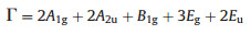
|
Here "g" presents the active mode of Raman while "u" displays the IR (Infra-Red) active mode of Raman [39]. Raman spectra of BiOCl show three strong peaks at 57.75, 145 and 199.45 cm–1 and a weak peak at 394.07 cm–1 (Fig. 3a). The strong peak at 57.75 cm–1 ascribed to A1g internal stretching mode of Bi–Cl, the peak at 199.45 cm–1 assigned to the Eg internal stretching mode of Bi–Cl and masked by 145 cm–1. The peak at 145 cm–1 is due to A1g internal stretching mode of Bi–Cl. Moreover, the weak peak at 394.07 cm–1 comes from Eg and B1g modes of Raman which was formed by the oxygen atoms motion [33].
Notably, the Raman peaks for BiPO4 at 200 and 300 cm–1 was attributed to Bi–O symmetric bending vibration, although the others peak in spectrum belongs to the symmetric and antisymmetric stretching modes of the PO4 tetrahedron. The spectrum peaks at 450–600 cm–1 were observed due to the v4 bending modes of PO4, peaks at 380–450 cm–1 and 950-1100 cm–1 were credited to the v1 symmetric and v3 antisymmetric stretching modes of the PO4 respectively as presented in Fig. 3b [40]. Raman spectrum of BiOCl/BiPO4 shows the characteristics of both catalyst BiOCl and BiPO4 (Fig. 3c) while the Raman spectra of TiO2 particles presents a set of peaks at 138.4, 392.53, 510.83 and 635.92 cm–1 were due to the major anatase phase along with the weak peak of minor rutile phase at 446 cm–1 as illustrated in Fig. 3d [41].
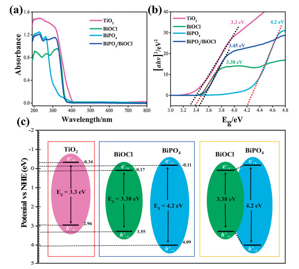
The optical properties of photocatalysts were examined by UV– vis DRS (Fig. 4a). The absorption band of BiOCl appears at about 361 nm [42], and BiPO4 could only respond to the deep UV region at about 277 nm [43]. The heterojunction of BiPO4/ BiOCl shows the edge band of both photocatalysts at 361 and 277 nm. TiO2 shows absorption band at 400 nm representing the effective absorption to near visible light to UV range and bandgap was calculated by the Tauc plot (Fig. 4b). Further, the band edge potential of catalysts (Fig. 4c), was assessed by using the bandgap and geometric mean of constituent elements electronegativity inconsistency with the literature [44].

|
Download:
|
| Fig. 4. (a) UV–vis absorption spectrum, (b) the Tauc plot, (c) band gap energies and band edge potentials of photocatalysts. | |
The photocatalytic performance of the prepared catalysts was evaluated by the degradation and defluorination ratio of PFOA under 254 nm UV light as shown in Fig. 5. BiOCl exhibited the highest photocatalytic performance as compared to BiPO4/BiOCl, BiPO4, and TiO2 (P25), while the direct photolysis (without photocatalyst) of PFOA was negligible after the first 15 min as observed in Fig. 5a. It has been reported in the literature that direct photolysis of PFOA is highly dependent on reaction intermediates [45, 46]. The concentration of intermediates (carboxylic acids) increase with time which effects on degradation, implying that PFOA undergoes a chain reaction for the removal of CF2 unit. Therefore, this could be the reason for the slow photolytic degradation of PFOA after the first 15 min. The degradation efficiency of PFOA was about 99.99%, 66.05% and 55.29% for bismuth-based photocatalysts, TiO2, and control experiment after 45 min, respectively (Fig. 5b). Notably, the time for complete degradation of PFOA over the BiOCl was only about 30 min, which was much shorter than the corresponding bismuth-based catalysts. Photocatalytic activity of the reference catalyst TiO2 (P25) was less as compared to bismuth-based catalysts under the same reaction condition. The photocatalysts activity order for PFOA degradation was without photocatalysts < TiO2 (P25) < BiPO4 < BiPO4/BiOCl < BiOCl (Figs. 5a and b). The PFOA degradation rate constant was calculated by first decay model order (-ln(C/C0) = kt), where C0 is the initial concentration of PFOA, C is the final PFOA concentration after the reaction, "t" and "k" is the rate constant. Fig. 5c demonstrates the degradation rate constant of PFOA by BiOCl, BiPO4, and BiPO4/BiOCl catalysts were 0.09297, 0.06384 and 0.05282 min-1, which was almost 6, 4 and 3 times higher than TiO2 (P25) while 9, 6 and 5 times higher than without the catalyst respectively. In addition, the intermediates formation and mineralization process during PFOA degradation reaction were monitored through IC. Fig. 5d shows the generation of inorganic fluoride (F-) and formate ions concentration during the degradation reaction, proved the efficient photocatalytic degradation of PFOA. The F- ion concentration in BiOCl, BiPO4, and BiPO4/BiOCl reaction system was more significant as compared to TiO2 (P25) and without photocatalyst. The main intermediates in PFOA degradation were formate and F- ions which rapidly reached their maximum concentration after 60 min of photodegradation reaction, indicating the direct C—F bond cleavage in PFOA [16]. On the basis of all above-mentioned results, PFOA could be effectively degraded by bismuth-based photocatalysts under UV light irradiation.

|
Download:
|
| Fig. 5. (a) PFOA degradation with bismuth-based catalysts and reference TiO2 (P25) photocatalyst under 254 nm UV light, (b) PFOA degradation efficiency, (c) apparent reaction rate constants for PFOA degradation, (d) removal ratio of fluoride (F-) and formic acid concentration during PFOA degradation after 60 min. Reaction conditions: [PFOA] = 20 ppm, [catalyst] = 0.05 g of each. All experiments were repeated three times at the natural pH of PFOA solution and the average data is presented here. | |
The probable explanation for the higher photocatalytic performance of bismuth-based catalysts is mainly attributed to their wide band gap. Bismuth-based catalysts have more positive valence band potential as compare to TiO2 (P25) [47]. The photogenerated holes of bismuth-based catalysts exhibit stronger oxidation ability, resulting in higher activity for PFOA degradation. Bismuth-based catalysts also possess a high adsorption capacity for pollutants. It can be seen that (Fig. 5a), the amount of PFOA adsorbed by bismuth-based catalysts was higher than TiO2 (P25) due to the presence of specific binding sites and oxygen vacancies which tightly bound the PFOA on bismuth-based catalysts. The higher adsorption capacity of PFOA on bismuth-based catalyst could be one reason for the more efficient PFOA photocatalytic degradation.
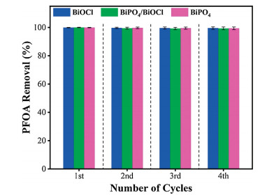
However, BiOCl exhibited the highest photoactivity among other bismuth-based catalysts, primarily due to its unique intrinsic layered structure which provides a driving force for promoting the charge separation. The more positive valence band potential, PFOA adsorption and unique morphology of bismuth-based catalysts could benefit the adsorption of pollutant (PFOA) and subsequent reactions that can promote the degradation rate in the bismuthbased photocatalytic system. Moreover, the reusability test was conducted to check the stability of bismuth-based catalysts (Fig. 6). After four times of consecutive cycles, the bismuth-based catalysts showed exceptional performance for PFOA removal suggesting that they were very stable for real applications, especially in wastewater treatment.

|
Download:
|
| Fig. 6. The reusability and stability test of bismuth-based catalysts for PFOA removal after 60 min. Error bars presents the standard deviation of three times repeated experiments and after each cycle, the catalysts were filtered, washed with deionized water and dried. | |
In summary, we successfully presented the photocatalytic performance of bismuth-based photocatalysts in comparison with TiO2 (P25) for significant degradation of highly persistent organic acid PFOA under UV irradiation. Bismuth-based photocatalysts showed an efficient photocatalytic performance for PFOA degradation. BiOCl shows 99.99% degradation of PFOA within 30 min while the other two photocatalysts (BiPO4 and BiPO4/BiOCl) degrade it within 45 min. All bismuth-based catalysts were synthesized by hydrothermal method and the catalysts structure, purity and crystallinity were analyzed by using different characterization techniques. This work provides a significant method for persistent organic pollutant removal in wastewater.
AcknowledgmentsThe authors gratefully acknowledge financial support from Ministry of Science and Technology of the People's Republic of China (Nos. 2016YFE0112200 and 2016YFC0202700), National Natural Science Foundation of China (Nos. 21507011, 21677037 and 21607027), and Natural Science Foundation of Shanghai (Nos. 19ZR1471200, 17ZR1440200).
Appendix A. Supplementary dataSupplementary material related to this article can be found, in the online version, at doi:https://doi.org/10.1016/j.cclet.2019.07.058.
| [1] |
Y. Izumi, Coord. Chem. Rev. 257 (2013) 171-186. DOI:10.1016/j.ccr.2012.04.018 |
| [2] |
O. Akhavan, ACS Nano 4 (2010) 4174-4180. DOI:10.1021/nn1007429 |
| [3] |
Y. Feng, H. Cheng, J. Han, et al., Chin. Chem. Lett. 28 (2017) 2254-2258. DOI:10.1016/j.cclet.2017.10.025 |
| [4] |
R. Qiao, M. Mao, E. Hu, et al., Inorg. Chem. 54 (2015) 9033-9039. DOI:10.1021/acs.inorgchem.5b01303 |
| [5] |
M. Ding, J. Zhou, H. Yang, et al., Chin. Chem. Lett. (2019) https://doi.org/10.1016/j.cclet.2019.05.029.
|
| [6] |
Q. Chen, L. Chen, J. Qi, et al., Chin. Chem. Lett. 30 (2019) 1214-1218. DOI:10.1016/j.cclet.2019.03.002 |
| [7] |
J. Han, Y. Bian, X. Zheng, et al., Chin. Chem. Lett. 28 (2017) 2239-2243. DOI:10.1016/j.cclet.2017.08.031 |
| [8] |
K. Nakata, A. Fujishima, J. Photochem. Photobiol C:Photochem. Rev. 13 (2012) 169-189. DOI:10.1016/j.jphotochemrev.2012.06.001 |
| [9] |
A. Li, W. Zhu, C. Li, et al., Chem. Soc. Rev. 48 (2019) 1874-1907. DOI:10.1039/C8CS00711J |
| [10] |
Y. Qin, H. Li, H. Dong, et al., New J. Chem. 42 (2018) 12437-12448. DOI:10.1039/C8NJ02057D |
| [11] |
X. Liu, J. Zhong, J. Li, et al., Appl. Phys. A 119 (2015) 1203-1208. DOI:10.1007/s00339-015-9181-5 |
| [12] |
S.G. Babu, P. Karthik, M.C. John, et al., Ultrason. Sonochem. 50 (2019) 218-223. DOI:10.1016/j.ultsonch.2018.09.021 |
| [13] |
M. Ji, Z. Zhang, J. Xia, et al., Chin. Chem. Lett. 29 (2018) 805-810. DOI:10.1016/j.cclet.2018.05.002 |
| [14] |
J. Hölzer, T. Göen, K. Rauchfuss, et al., Int. J. Hyg. Environ. Health 212 (2009) 499-504. DOI:10.1016/j.ijheh.2009.04.003 |
| [15] |
Y.P. Peng, H. Chen, C. Huang, Appl. Catal. B:Environ. 209 (2017) 437-446. DOI:10.1016/j.apcatb.2017.02.084 |
| [16] |
Y. Wang, P. Zhang, G. Pan, et al., J. Hazard. Matter. 160 (2008) 181-186. |
| [17] |
M. Sha, P. Xing, B. Jiang, Chin. Chem. Lett. 26 (2015) 491-498. DOI:10.1016/j.cclet.2015.03.038 |
| [18] |
G. Liu, H. Zhou, J. Teng, et al., Chem. Eng. Sci. 371 (2019) 7-14. DOI:10.1016/j.cej.2019.03.249 |
| [19] |
J.M. Graber, C. Alexander, R.J. Laumbach, et al., J. Expo. Sci. Environ. Epidemiol. 29 (2019) 172-182. DOI:10.1038/s41370-018-0096-z |
| [20] |
A. Koch, R. Aro, T. Wang, et al., TrAC-Trends Anal. Chem. (2019), doi: http://dx.doi.org/10.1016/j.trac.2019.02.024.
|
| [21] |
J. Zhong, Y. Zhao, L. Ding, et al., Appl. Catal. B:Environ. 241 (2019) 514-520. DOI:10.1016/j.apcatb.2018.09.058 |
| [22] |
B. Yang, C. Jiang, G. Yu, et al., J. Hazard. Matter. 299 (2015) 417-424. DOI:10.1016/j.jhazmat.2015.06.033 |
| [23] |
S. Takagi, F. Adachi, K. Miyano, et al., Water Res. 45 (2011) 3925-3932. DOI:10.1016/j.watres.2011.04.052 |
| [24] |
H. Tang, Q. Xiang, M. Lei, et al., Chem. Eng. Sci. 184 (2012) 156-162. DOI:10.1016/j.cej.2012.01.020 |
| [25] |
B. Gomez-Ruiz, P. Ribao, N. Diban, et al., J. Hazard. Matter. 344 (2018) 950-957. DOI:10.1016/j.jhazmat.2017.11.048 |
| [26] |
Y. Wang, P.Y. Zhang, G. Pan, et al., Chin. Chem. Lett. 19 (2008) 371-374. DOI:10.1016/j.cclet.2007.11.007 |
| [27] |
M. Sansotera, F. Persico, C. Pirola, etal., Appl.Catal. B:Environ. 148 (2014) 29-35. |
| [28] |
H. Cheng, J. Han, I. Nabi, et al., Appl. Catal. B:Environ. 248 (2019) 441-449. DOI:10.1016/j.apcatb.2019.02.049 |
| [29] |
W. Deng, H. Zhao, F. Pan, et al., Environ. Sci. Technol. 51 (2017) 13372-13379. DOI:10.1021/acs.est.7b04206 |
| [30] |
W. Liu, D. Zhong, Z. Dai, et al., J. Alloys Compd. 780 (2019) 907-916. DOI:10.1016/j.jallcom.2018.12.003 |
| [31] |
S.P. Sahu, M. Qanbarzadeh, M. Ateia, et al., Environ. Sci. Technol. Lett. 5 (2018) 533-538. DOI:10.1021/acs.estlett.8b00395 |
| [32] |
F. Duo, Y. Wang, X. Mao, et al., Appl. Surf. Sci. 340 (2015) 35-42. DOI:10.1016/j.apsusc.2015.02.175 |
| [33] |
U. Sulaeman, H. Pratiwi, A. Riapanitra, et al., Adv. Mater. Res. 911 (2014) 92-96. |
| [34] |
G. Zhu, M. Hojamberdiev, K. Katsumata, et al., Adv. Power. Technol. 25 (2014) 1292-1303. DOI:10.1016/j.apt.2014.03.008 |
| [35] |
S.P. Sahu, E.L. Cates, J. Phys. Chem. C 121 (2017) 10538-10545. DOI:10.1021/acs.jpcc.7b00776 |
| [36] |
D. Liu, W. Cai, Y. Wang, et al., Appl. Catal. B:Environ. 236 (2018) 205-211. DOI:10.1016/j.apcatb.2018.05.022 |
| [37] |
W. Fateley, N.T. McDevitt, F.F. Bentley, Appl. Spectrosc. 25 (1971) 155-173. DOI:10.1366/000370271779948600 |
| [38] |
S. Cao, C. Guo, Y. Lv, et al., Nanotechnology 20 (2009) 275702. DOI:10.1088/0957-4484/20/27/275702 |
| [39] |
A. Rulmont, Spectrochim. Acta A Mol. Biomol. Spectrosc. 30 (1974) 311-313. DOI:10.1016/0584-8539(74)80235-7 |
| [40] |
C. Pan, J. Xu, Y. Chen, et al., Appl. Catal. B:Environ. 115 (2012) 314-319. |
| [41] |
M. Pelaez, P. Falaras, A.G. Kontos, et al., Appl. Catal. B:Environ. 121 (2012) 30-39. |
| [42] |
K.L. Zhang, C.M. Liu, F.Q. Huang, et al., Appl. Catal. B:Environ. 68 (2006) 125-129. DOI:10.1016/j.apcatb.2006.08.002 |
| [43] |
J. Cao, B. Xu, H. Lin, et al., Chem. Eng. J. 228 (2013) 482-488. DOI:10.1016/j.cej.2013.05.008 |
| [44] |
M. Butler, D. Ginley, J. Electrochem. Soc. 125 (1978) 228-232. DOI:10.1149/1.2131419 |
| [45] |
Z. Song, H. Tang, N. Wang, et al., Adv. Environ. Res. 3 (2014) 185-197. DOI:10.12989/aer.2014.3.3.185 |
| [46] |
X. Liang, J. Cheng, C. Yang, et al., Chem. Eng. J. 298 (2016) 291-299. DOI:10.1016/j.cej.2016.03.150 |
| [47] |
P. Ye, J. Xie, Y. He, et al., Mater. Lett. 108 (2013) 168-171. DOI:10.1016/j.matlet.2013.06.059 |