 2019, Vol. 30


b Jiangsu Key Laboratory of Electrochemical Energy-Storage Technologies, College of Materials Science and Technology, Nanjing University of Aeronautics and Astronautics, Nanjing 210016, China;
c King Abdullah University of Science and Technology, KAUST Catalysis Center(KCC), Advanced Catalytic Materials, Thuwal 23955, Saudi Arabia;
d State Key Laboratory of Physical Chemistry of Solid Surfaces, and Department of Chemistry, College of Chemistry and Chemical Engineering, Xiamen University, Xiamen 361005, China;
e Hefei National Laboratory for Physical Sciences at the Microscale, and School of Chemistry and Materials Science, University of Science and Technology of China, Hefei 230026, China;
f Physical Science Division, Pacific Northwest National Laboratory, Richland, WA 99352, United States;
g State Key Laboratory of Oil and Gas Reservoir Geology and Exploitation, Southwest Petroleum University, Chengdu 610500, China;
h The Center of New Energy Materials and Technology, School of Materials Science and Engineering, Southwest Petroleum University, Chengdu 610500, China;
i School of Environmental Science and Engineering, Shanghai Jiao Tong University, Shanghai 200240, China;
j Centre for Clean Environment and Energy, Gold Coast Campus, Griffith University, Gold Coast 4222, Australia;
k Key Laboratory of Materials Processing and Mold(Zhengzhou University), Ministry of Education, Zhengzhou University, Zhengzhou 450002, China
Bing Ding, Hui Dou*
1.1. StatusThe tunable pore structure and the versatility in both inorganic and organic building blocks endow MOFs electronically conductive or "ionically" conductive properties, which makes MOFs as promising candidate materials for energy-storage devices. In recent years, considerable scientific efforts have been denoted to fundamental understanding and technology development for exploring MOFs for supercapacitors and lithium batteries.
1.2. Current and future challengesCompared with secondary batteries, supercapacitors can store and deliver charge in seconds by formation of electrochemical doublelayeron the surfaceof theporous electrodeor redox reactions involving the surface regions of electrode materials. However, long-standing challenge of thick electrodes with high areal capacitance is still faced by supercapacitors [1]. Electronically conductive MOFs have been identified as promising electrode materials with high gravimetric/volumetric capacitances. Approaches for preparing conductive MOFs include: (1) modifying the organic and inorganic building blocks based on the structural features and principles of conductive MOFs; (2) application of lattice and chemical strain; and (3) post-synthetic introduction of external guest molecules and/or highly conductive materials (such as graphene).
Lithium batteries, by using metal lithium anode, are considered attractive in a range of perspectives, including the high theoretical capacity (3860 mA h/g) and the negative potential (-3.040 V versus standard hydrogen electrode) of lithium. For lithium anode, realizing homogeneous lithium ion flux and preventing side reactions on its surface is critical for suppressing lithium dendrite growth and enabling high Coulombic efficiency in lithium batteries. Inspired by the gas separation realized by the tunable pore, MOFs are expected to host guest molecule/ion and provide the possibility for desirable molecular/ionic sieving/selective transportproperties, thus avoiding performance deterioration caused by the transports of undesired molecule/ion [2]. Therefore, MOF-based (modified) separators and MOF-based solid-state electrolytes were developed for lithium batteries, including lithium-sulfur (Li-S) batteries and all-solid-state lithium batteries (ASSLBs) [3-6].
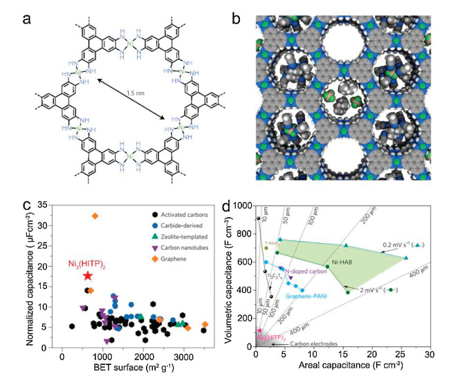
1.3. Advances in science and technology to meet challengesDincǎ et al. described the first example of conductive Ni3(HITP)2 (HITP = 2, 3, 6, 7, 10, 11-hexaiminotriphenylene) MOF as sole electrode material for supercapacitors (Fig. 1a), which is composed of stacked π-conjugated 2D layers and 1D cylindrical channels and exhibits a surface area of 630 m2/g and an electronic conductivity of over 5000 S/m [7]. Importantly, the 1D open channels are sufficiently spacious to accommodate large electrolyte ions (Fig. 1b). Consequently, the Ni3(HITP)2 electrode could exhibit a high specific capacitance of 18 μF/cm2 (Fig. 1c), which is higher than those of any porous carbon electrodes. The denser Ni3(HITP)2 electrode with a density of 1.1 ± 0.2 g/cm3 can still exhibit a volumetric capacitance up to 118 F/cm3. Inspired by the higher charge-storage ability of pseudocapacitive behavior, conductive MOFs with pseudo-capacitive redox centers are excepted high capacitances. For example, as profited from redox-active hexaaminobenzene (HAB) center, submillimeter-thick 2D conductive Ni-HAB MOF electrode exhibits a high volumetric capacitance up to 760 F/cm3 and high areal capacitance over 20 F/cm2 (Fig. 1d) [1]. Therefore, the designability of pore chemistry and electrochemistry of MOFs allows the further development of new conductive MOFs with higher gravimetric/volumetric capacitance and better rate capability.

|
Download:
|
| Fig. 1. (a) Molecular structure of Ni3(HITP)2 MOF. (b) Relative size of pores, Et4N+ cation and BF4- anion, and acetonitrile molecule. (c) Comparison of areal capacitances of Ni3(HITP) with various porous carbon materials. (d) Comparison of the volumetric and areal capacitance of Ni-HAB electrodes (green area) with other materials. (a–c) Reproduced with permission [7]. Copyright 2017, Springer. (d) Reproduced with permission [1]. Copyright 2018, Springer. | |
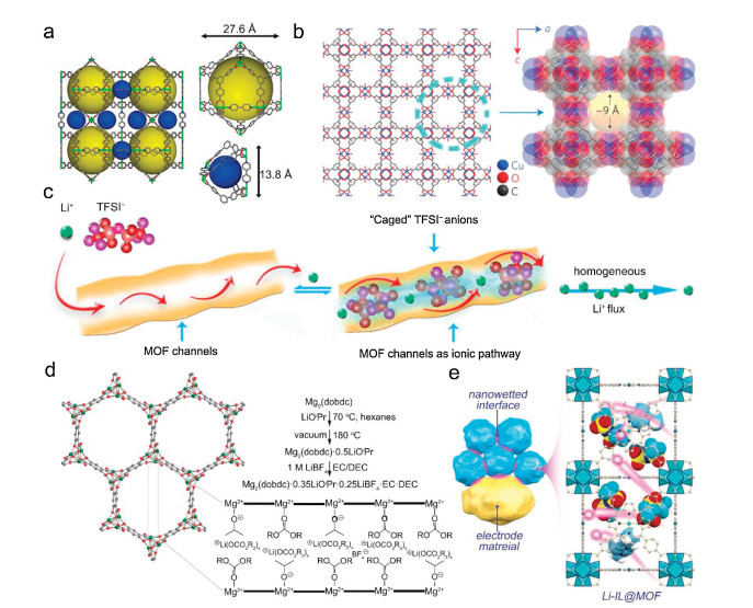
The angstrom-scale pores in MOF can affect could control the transport of the carrier ions and avoid unfavorable transport of other species. Several MOFs have been proved effective in confining elemental sulfur to minimize the diffusion of lithium polysulfide intermediates in the organic electrolyte and prevent the side reactions on lithium anode surface (so-called "shuttle effect") [8, 9]. Compared with physical confinement, the chemical interaction between the polysulfides and the MOF exhibits strong ability of polysulfides trapping ability. For example, the interaction between Lewis acidic Ni(Ⅱ) center in Ni-MOF (Fig. 2a) and the polysulfide base successfully trap the soluble polysulfide intermediates within the pores, which endows Ni-MOF/S cathode a high capacity retention of 89 % after cycling at 0.1 C for 100 cycles [8]. Compared with porous polymer separator, the free-standing HKUST-1@GO separator with a 3D channel structure and highly ordered micropores (size window of × 9 Å, Fig. 2b) selectively sieve lithium ions while blocking polysulfides intermediates [10]. The Li-S battery using HKUST-1@GO separator possesses low capacityfading rates of 0.019 % per cycle over 1500 cycles. Furthermore, experiment results and theorical simulation indicate that the homogenous micropores in HKUST-1 MOF can restrict the TFSI- anion transport and facilitate a homogeneous lithium ion flux, therefore control the ion transport in pristine liquid electrolytes (Fig. 2c) [2]. Consequently, the MOF host enables a stable Li-metal plating/stripping at a practically high current density (10 mA/cm2).

|
Download:
|
| Fig. 2. Crystal structure of (a) Ni-MOF and (b) HKUST-1. (c) The selective lithium ionic transport in the pores of HKUST-1. (d) Crystal structure and preparation route of Mg2(dobdc) MOF. (e) Schematic illustration for the nanowetted electrode/Li-IL@MOF electrolyte interface and crystal structure of Li-IL@MOF electrolyte. (a) Reproduced with permission [8]. Copyright 2017, American Chemical Society. (b) Reproduced with permission [10]. Copyright 2016, Springer. (c) Reproduced with permission [2]. Copyright 2018, Elsevier. (d) Reproduced with permission [11]. Copyright 2011, American Chemical Society. (e) Reproduced with permission [13]. Copyright 2018, Wiley. | |
ASSLBs possess high energy density and safety, standing out among the next-generation secondary battery technologies. Among all the components in ASSLBs, solid-state electrolyte has critical influences on the electrochemical reaction kinetics and the performances. Long and co-workers reported the pioneered work on MOF-based solid-stateelectrolyte, which was prepared by grafting lithium isopropoxide (LiOPr) in Mg2(dobdc) (dobdc4- = 1, 4-dioxido-2, 5-benzenedicarboxylate) and subsequent infiltration with LiBF4 in ethylene carbonate/ diethyl carbonate (EC/DEC) (Fig. 2d) [11].With anionsbeingbondedto unsaturated Mg2+ cation clusters in the Mg2(dobdc) MOF, the room-temperature ionic conductivity of this new-type solid-state electrolyte reaches up to 3.1 ×10⁻⁴ S/cm. This approach could be extended to develop other solid-state electrolytes by employing new MOF hosts with open metal sites and suitable pore diameter [12]. Besides ionic conductivity, properties, including chemical compatibility at wide temperature, electrochemical stability, and fast ionic transport kinetics at the electrode/solid-state electrolyte interface also need to be considered. The lithium containing ionic liquid@MOF-525(Cu) MOF (Li-IL@MOF) electrolyte (Fig. 2e) was expected to exhibit a high room-temperature ionic conductivity of 3.0 × 10⁻⁴ S/cm, good compatibilities against both metal lithium and active electrodes, and low interfacial resistances, which enables lithium|LiFePO4 all-solid-state cell remarkable performance over a wide temperature range of -20 × 150 ℃ [13]. All these research progresses highlight the promising potentials of MOF-based solid-state electrolyte in high-energy density ASSLBs.
1.4. Concluding remarks and prospectsOwning to the tunable pore and high surface area, various MOFs have shown great potential in energy-storage devices. Furthermore, the structure tunability and building block designability of MOFs will allow the further development of new MOFs with unique features, such as stacked π-conjugated systems, redox-active centers and/or unsaturated sites. In the further research, high-throughput simulation and high-throughput synthesis are expected to be effective in accelerating the application of MOFs for energy-storage. In addition, most of MOFs are particulate morphological crystals and mechanically brittle. Film-forming technologies operated at low temperature, including organic-inorganic hybridization and molecular layer deposition, may provide new possibilities for preparing MOF membranes (films). Further fundamental understanding of the lithium ionic transport mechanisms, optimizing the lithium ionic conductivity and interfacial ionic transport kinetics could promote the developments of MOF-based solid-state electrolytes.
1.5. AcknowledgmentsThe authors would like to gratefully acknowledge the National Natural Science Foundation of China (Nos. 51672128, 21875107 and 21905134), Natural Science Foundation of Jiangsu Province (No. BK20170778), and China Postdoctoral Science Foundation (No. 2018M632300).
2. MOF and MOF derived solids in electrocatalytic applicationsJorge Gascon*
2.1. StatusThe application of metal organic frameworks and derived materials in electrocatalysis has mainly focused on water oxidation and reduction (OER and HER) and more recently in CO2 electroreduction. MOFs have been directly used as catalysts; in this case, both the atomically dispersed metal nodes and the organic linker can be engineered into active sites [14]. On the other hand, MOFs can also be used as catalyst precursors through the MOF mediated synthesis [15, 16]. In this approach, the MOF is decomposed under controlled conditions to lead to the clustering of its metal component into small nanoparticles or to the formation of single atom catalytic sites. At the same time, the organic component (the linker) rearranges into a carbonaceous matrix that may be conductive.
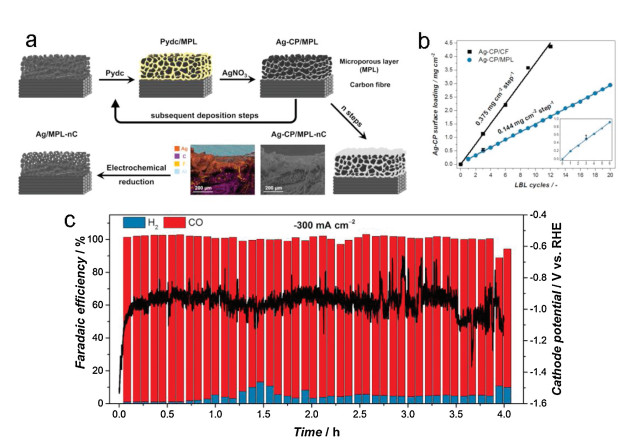
2.2. Current and future challengesThe OER is arguably the most challenging electrochemical reaction from the ones described above, and a necessary step to close the reduction cycle [17, 18]. This is, to a great extent due to the very high pH needed to achieve good kinetics. This is obviously a drawback for most MOFs, which are simply not stable under such reaction conditions. This lack of stability under reaction conditions together with the fact that most MOFs are insulators and the few conductive MOFs known to date display moderate to poor conductivities, both point to the MOF mediated synthesis as the most feasible approach towards the development of competitive MOF based electrocatalysts. Recently, Want et al. demonstrated the potential of this approach by depositing fine layers of a Ag based coordination polymer on top of electrode surfaces followed by in situ electroreduction of the metal nodes, leading to an electrocatalysts for the direct production of CO from CO2 with optimized metal utilization (Fig. 3) [19].

|
Download:
|
| Fig. 3. Scheme of the preparation of Ag/MPL catalysts, the sequential deposition of Ag-CP via the alternating adsorption of the dicarboxylic linker and the metal node, and the cross-sectional elemental maps of C, F, Ag and F (a). Fluorine can be found on the PTFE-treated carbon fabric, while Al signal comes from the sample holder. Increasing surface loading in subsequent deposition steps on bare carbon fiber and MPL/carbon cloth (b). CO2ER performance of the Ag/MPL-3C electrode in a gas-fed zero gap flow electrolyzer at -300 mA/cm2 (c). (a–c) Reproduced with permission [19]. Copyright 2017, Royal Society of Chemistry. | |
2.3. Advances in science and technology to meet challenges
The development of conductive MOFs with redox active centers will be necessary for pristine MOFs to stand out among other materials. When it comes to the use of MOFs as catalyst precursors, the development of methods for the fabrication of thin coatings on electrodes and the further transformation of these coatings into electroactive nanoparticle-based electrodes seems like the right approach to follow. In either way, the use of MOFs should further boost electrocatalytic performance per metal center, allowing in this way high activity per unit surface.
2.4. Concluding remarks and prospectsMetal organic frameworks offer a great deal of opportunities in the development of efficient electrocatalysts. Not only from a structural point of view but especially from their easy fabrication and interfacing with different supports. In the future, such protocols could be used for the manufacture of electrolyzers with outstanding catalytic performance.
3. Metal-organic frameworks for photoelectrocatalysisXiang-Jian Kong*, Yujie Xiong*
3.1. StatusPhotoelectrochemical (PEC) technology which simultaneously merges together the advantages of photocatalysis and electrocatalysis has drawn increasing attention, since the first PEC system for water splitting was discovered in the 1970s [20]. As the two essential components of PEC system, photocathode normally employs p-type semiconductors to complete reduction reaction and photoanode fully relies on n-type semiconductors for oxidation process. Although the investigation on the inorganic semiconductor materials for PEC reaction procedures has received much interest in the last two decades, there are still many challenges restricting their development and application, e.g., low catalytic activity, inefficient electron-hole separation, limited light absorption, slow interfacial charge dynamics and photocorrosion.
Metal-organic frameworks (MOFs), as a class of unique organicinorganic hybrid crystalline porous materials [21], represent an ideal candidates as PEC materials because of their irreplaceable advantages including ultra-high surface area, hierarchical porosity, structural diversity and tenability [22]. Firstly, the organic ligands in MOFs can be used as antennas to receive light to sensitize and activate their neighboring metal clusters. Through post-synthesis modification of MOFs, it is convenient to enhance and broaden the sunlight absorption for semiconductors as photosensitizers. Secondly, the metal nodes in MOFs can be viewed as co-catalysts to supply sufficient active sites for adsorbing and activating reactants. Thirdly, the regular channels of MOFs allow sieving small molecules to selectively reach catalytic activity sites, thus achieving more effective charge separation and higher catalytic selectivity [23]. Finally, MOFs can be used as precursors to prepare MOFs-derived porous nanomaterials as parts of catalysts for the PEC system.
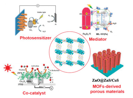
3.2. Challenges and advancesAccording to the roles of the MOFs in PEC processes, the application of MOFs for PEC can be summarized as the following four aspects (Fig. 4) [22]. (1) MOFs as photosensitizers. An important reason for the low energy conversion efficiency of many semiconductors is the weak absorption of light due to the wide band gaps. The organic ligands in MOF skeleton can effectively enhance the light harvesting of heterostructure semiconductors by appropriate modification, thus acting as an effective photosensitizer. For example, the organic ligands in the Ti-based MOF under light irradiation can produce photoexcited electrons, which further transfer to Ti-oxo clusters to complete reduction reaction. If introducing electron-donating amine group into the skeletons of organic ligands, the band gap will be narrowed down and light absorption spectrum is bound to red shift [24]. Following the idea, three core-shell TiO2/MIL-125(NH2)x (x = 0, 1, or 1, 2) hybrid nanostructures were designed to proceed the PEC water oxidation process. With increasing the number of amino groups in organic ligands, the absorption ranges were extended from ultraviolet to visible light region [25]. (2) MOFs as co-catalysts. Catalytic reactions typically occur on the surface of semiconductors while nanosized semiconductors usually lack sufficient active sites. The metal nodes of MOF can provide efficient active sites for the adsorption and activation of reactants and serve as co-catalysts for PEC reactions, if the channel of MOF is large enough for small reactant molecules to pass through. For example, good PEC performance can be obtained by loading cobalt-containing ZIF9 on the surface of Co3O4 NWs. This is mainly because CO2 molecules can be adsorbed on the cobalt ions of ZIF9 nodes through the channels of ZIF9, which in turn effectively activate CO2 in the PEC system [26]. Furthermore, MOFs also can be used as ideal supports to host different metal active sites. Bimetallic metals in MOFs could provide more active sites to synergistically improve the performance of PEC reactions [27]. (3) MOFs as mediators. A major challenge to improve the performance of PEC is how to improve the separation and transfer efficiency of photogenerated electron-hole pairs. By modifying the composition of MOFs, the HOMO and LUMO orbital levels of MOF can be easily regulated to match that of semiconductors. As such, in the heterojunction systems constructed by semiconductor and MOF, MOFs could serve as mediators to promote the charge separation and transfer. In sharp contrast to simple physical adsorption, close interfacial contact, e.g., covalent interaction, is beneficial to the rapid charge transfer. In addition, MOFs themselves can also be used as materials for PEC. Compared with semiconductor photocathodes, PEC behavior of MOFs-based photoelectrodes can switch from photoanode to photocathode, when appropriate redox medium is introduced [28]. (4) MOFs-derived porous materials. MOFs can also be used as precursors to obtain porous nanomaterials with high specific surface area by high-temperature sintering. The obtained material has abundant catalytic active sites and can be used as heterojunction to cooperate with other semiconductors to promote electron transfer. In addition, MOFs are used to generate single-metal-atom reactive sites with the drastic reactive processes that occur at high temperature. Metal oxides, sulfides or carbides with porous structures derived from MOFs can also be obtained using MOFs as precursors [29]. These special porous nanostructures can expose abundant active centers or form heterojunctions to facilitate electron-hole separation in PEC reactions.

|
Download:
|
| Fig. 4. The roles of the MOFs in the PEC application. Reproduced with permission [22]. Copyright 2019, Elsevier. | |
3.3. Concluding remarks and prospects
Overall, MOFs have proven to be one of the most versatile materials in the last few years. Compared to researches on MOF applications, the study of MOF for PEC applications is still rare. Indeed, MOFs themselves are crystalline porous materials, which have metal nodes to offer catalytic active sites and organic ligands to serve as electronic transporter, representing ideal platforms for addressing the PEC systems. MOFs could serve as photosensitizes, co-catalysts, mediators or porous material precursors in PEC systems. However, the MOFs-mediated artificial photosynthesis for specific PEC systems, such as CO2 reduction, water oxidation or N2 fixation, should be fully explored to expand the potential applications of MOFs. The synergetic conjunction of photocatalysis and electrocatalysis could facilitate to separate the photo-induced electrons and holes under applied electric field. Furthermore, the band bending of the semiconductor@MOFs materials could compensate to the light harvesting and improve the performance PEC. Future research should explore the advantages of MOFs in PEC applications to fully understand their special functions. With further investigations, the efficient MOFs-based materials will open up new opportunities for conventional PEC photoelectrode systems that exhibit high performance for artificial photosynthesis.
3.4. AcknowledgmentsThis work was supported by the National Key R&D Program of China (No. 2017YFA0207301), the National Natural Science Foundation of China (Nos. 21725102, 21871224 and 21721001).
4. Design of advanced electrocatalysts based on aerogelsBin Cai*
4.1. StatusAerogels are synthetic solid materials with ultralow density, high continuous porosity and extremely large surface area, making them of immense importance in various applications such as catalysis, energy storage, piezoelectrics, thermoresistors, and sensors [30]. The research on aerogels has been originated from the pioneering work on the synthesis of silica aerogels based on tetramethoxysilane in the early 1930s [31]. Since then, research on functionalities and applications of aerogels has been extensively explored by widening the molecule-based precursors from inorganic (e.g., metal oxide, carbide) to organic (e.g., polymer, cellulose) and carbon (e.g., carbon nanotubes, graphene) materials [32]. For these conventional aerogels, their hydrogels are generally obtained from gelation of the solution of certain molecule precursors. It should be noted that this gelation process is usually based on condensation/polymerization reactions of the molecule precursors, thus restricting the possible precursor materials and limiting the modification of surface properties. Correspondingly, special interests shifted to the use of colloidal nanocrystals (NCs) as the precursors, which implies tremendous opportunities to design and synthesize aerogels with desired physical and chemical properties.
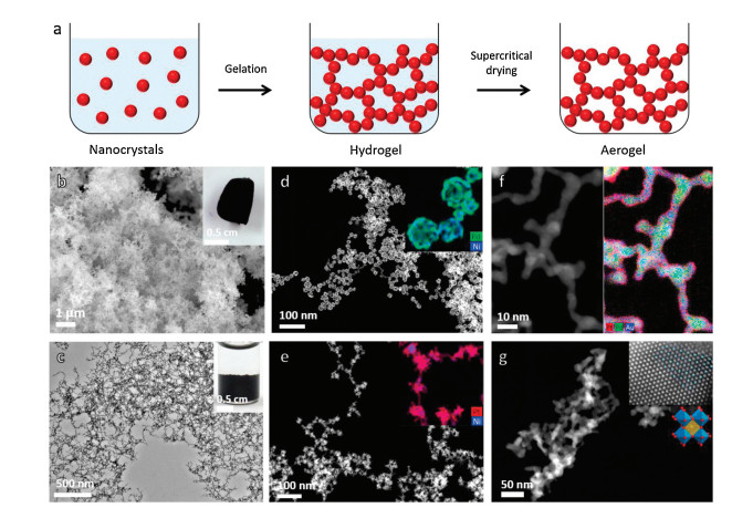
The combination of well-developed colloidal NCs and aerogel synthesis remained unfeasible until the groundbreaking research of the assemblies of semiconductor NCs into aerogel frameworks by the Brock group [33]. Afterwards, pure metallic aerogels evolved from pre-synthesized noble metal NCs were firstly accomplished in the Eychmüller group [34]. Their corresponding sol-gel process is based on the controllable destabilization (i.e., self-assembly) of the colloidal NCs which leads to the three-dimensional (3D) interconnected monolithic hydrogels soaked with solvent (Fig. 5) [35, 36].

|
Download:
|
| Fig. 5. An overview of the typical synthesis procedure and characterizations of aerogel electrocatalysts. (a) Scheme of the sol-gel synthesis route for NC-derived aerogel electrocatalysts. (b) Typical SEM and (c) TEM overview image of NC-derived metallic aerogels. Insets show the corresponding optical images of the aerogel and hydrogel. High-angle annular dark-field TEM images of hierarchical aerogels built on (d) Pd/Ni nanoshells. (e) Pt/Ni nanodendrites, (f) PdAu-Pt core-shell structured aerogels and (g) LaMnO3 perovskite oxide aerogels. Insets show the corresponding EDX elemental maps. and high-resolution TEM image. (a, c, e, f) Reproduced with permission [75]. Copyright 2018, Wiley. (b) Reproduced with permission [62]. Copyright 2017, Wiley. (d) Reproduced with permission [62]. Copyright 2015, Wiley. (g) Reproduced with permission [76]. Copyright 2019, American Chemical Society. | |
Over the past years, aerogels built from various metal and semiconductor NCs have proven to bridge the nano world with that of materials of macro dimensions that can be easily manipulated and processed while maintaining the nanoscale properties [37]. The resulting aerogels inherit the properties and functions from the parent NCs while maintaining the aerogel nature, which frequently leads to amplification of the inherited properties and results in features that are unique to the aerogels. For instance, they exhibit ultrahigh surface areas (semiconducting: ranging from 188 m2/g to 234 m2/g; metallic: ranging from 32 m2/g to 168 m2/g) and extremely low monolith densities (semiconductor: around 0.08 g/cm3; metallic: around 0.01 g/cm3) while the quantum confinement effect and highly electrocatalytic activity are maintained in the corresponding aerogels [36, 38].
4.2. Aerogels for electrocatalysisEver-increasing, energy-related environmental pollution has prompted scientific and industrial research for clean and sustainable energy sources and conversion devices to ultimately replace current fossil-fuel-based energy systems [39]. Fuel cells operated with hydrogen and oxygen (air) are widely believed to be among the next generation of energy conversion systems owing to their high efficiency and low emissions [40, 41]. One of the major obstacles for their broad application is the lack of low-cost, durable and efficient electrocatalysts for the anodic fuel oxidation reaction and the cathodic oxygen reduction reaction (ORR), whereby the slow kinetics of this reaction lead to major voltage losses in the fuel cells [42-46]. Numerous nanostructured materials have been developed in the past decades for catalyzing the ORR, including Pt-based metallic nanostructures [47-49] and heteroatom-doped carbon materials [50-52]. Among them, former remains the top choice for industrial development due to their high performance, even if Pt is a scarce and expensive metal [43].
Recent research efforts in this direction have led to significant improvements of Pt-based electrocatalysts in terms of morphology engineering, composition manipulation, size control and composite developments [53, 54]. In most cases, these electrocatalysts are supported on carbon black and rely on its high surface area to obtain adequate active site dispersion. However, the carbon support is partially responsible for the insufficient catalyst durability, since it corrodes under the high potential conditions (up to 1.6 V) that are present during PEFC start-up/shut-down and local fuel starvation, leading to catalyst particle detachment and loss of electrical contact [55, 56]. While carbon corrosion rates can be reduced by switching to graphitized carbons with lower surface area, support stability remains an important concern [57, 58].
In this respect, metallic aerogels, as one of the most promising type of unsupported electrocatalysts, provide opportunities to overcome this issue and are potentially less susceptible to other degradation phenomena due to their extended surface areas [56, 59]. The self-supportability of aerogels leads to a direct contact of the electroactive species with the conductive substrates, thus assuring a good integrity of the catalyst layers. Besides, the metallic aerogels also feature large surface area, high porosity mechanical stability and extended metallic backbones, which are beneficial for successful implementations [55].
4.3. Advances in aerogel electrocatalystsTo date, different types of metallic aerogels have been developed and tested as unsupported electrocatalysts for both anode and cathode reactions of fuel cells. Recently, cyclodextrin protected Pd [60], citrate protected PdxNi [61] and Ni-PdxPty [62] aerogels have been synthesized and subsequently investigated their electrocatalytic performances for ethanol oxidation reaction (EOR). Improved mass activities ranging from 3 to 10-fold higher than commercial Pd/C catalyst have been obtained. In addition, pure PtAg aerogels exhibited nearly 19 times higher mass activity toward formic acid oxidation reaction (FOR) as compared to the Pt black [63]. As for the cathodic reactions, pure PdxPt [64], PtxNi [65] and PtxCu [66] aerogels have been designed and evaluated as ORR electrocatalysts. Alloying with Pd or non-precious transition metals downshifts the D-band center of Pt metal, thus leading to a lower degree of adsorption of oxygenated species [53]. Together with the elimination of carbon support, largely improved ORR activity and durability were demonstrated on these Pt-containedc aerogels. In addition, pure Au and Pd aerogels have also been designed for bioelectrocatalysis [67, 68].
These efforts have produced plenty of excellent aerogel electrocatalysts, however, the development of metallic aerogels and the corresponding applications are still in the early stage. A number of challenges remain before the widespread implementation of these materials in practical areas can be realized. For instance, the diversity of morphologies and variety of components of the metallic aerogels is limited and further extension is necessary. Besides, scalable and low-cost strategies for the synthesis of series of metallic aerogels are necessary for promoting their wide applications in practical areas.
Along with the development of nanoscience, noble metal based NCs, which usually serve as nano building blocks (NBBs) for these aerogels, have been extensively investigated based on the surfactant-assisted precision synthesis that provides well monodispersity (size control), hierarchical structures (hollow, coreshell, dendritic, etc.) and controlled surface properties (alloying or type of facets) [69-72]. These fine-synthesized NCs usually exhibited improved performances in corresponding applications. For instance, Pt-based hollow NCs with ultra-thin walls and controllable facets largely reduced the use of noble metals and exhibited distinctive catalytic activities toward oxygen reduction [73]. Ultrathin Pd-Pt core-shell nanowires with large aspect ratio exhibited enhanced ORR mass and specific activities of up to 8.5 and 9.0 times higher than those of Pt/C, respectively [74]. However, it still remains challenging to implement these more complex NCs in the aerogel synthesis, as the demand of surfactant throughout the NC synthesis obstructs the destabilization-gelation step for aerogels [62]. As a result, the metallic aerogels reported to date are mainly derived from NPs with uncomplicated structures (generally solid spherical particles), which usually results in a nanowire-based backbone. The implementation of these shape-tuned NCs as NBBs for the synthesis of aerogels with desirable properties enabled a second stage of the NC-based aerogel research, which is defined as hierarchical aerogels. Different from the conventional aerogels with nanowire-like backbones, those hierarchical aerogels that evolved from fine-tuned NCs generally combine two levels of architectures: a 3D interconnected porous structure on the macroscale and a fine-tuned configuration at local backbones at the nanoscale. This combination "locks in" the inherent properties of the NBBs, so that the beneficial genes obtained by nano-engineering of the NBBs are retained in the resulting hierarchical aerogels. In this manner, the desirable properties of NCs derived from specific morphologies can be translated to aerogel monoliths and new applications become accessible with possibly far reaching consequences.
Linking aerogel research and nanotechnology, hierarchical aerogels with two levels of nanoconfigurations have also been reported based on shape-controlled NBBs or post-engineering of gel structures. Bimetallic hierarchical aerogels which are composed entirely of alloyed Pd/Ni hollow nanoshells were accomplished via a facile bottom-up method (Fig. 5d) [61]. The synergy of the transition metal doping, combined with the hollow building blocks and the three dimensional network structures make the Pd/Ni nanoshell aerogels promising electrocatalysts towards ethanol oxidation, among which the Pd83Ni17 aerogel shows a 5.6-fold enhanced mass activity compared to commercial Pd/C. By tuning the compositions, the morphology of the NBBs can be in situ engineered from HNSs to dendritic NCs and the structural growth mechanism underlying the galvanic replacement was revealed in terms of nanowelding of the particulate reaction intermediates (Fig. 5e) [62]. Combining the advantages from the joint hollowdendritic morphologies, the multimetallic alloying and the aerogel structures, the Ni-Pd60Pt40 aerogel exhibits remarkable electrocatalytic activity which is 10.6 and 7.6-fold higher than the state-of-the-art Pd/C and Pt/C catalysts, respectively. In addition to tuning NBBs, PdxAu-Pt core-shell structured hierarchical aerogels comprised of an ultrathin Pt shell and a composition-tunable alloyed core were synthesized via post-synthetic strategy, which could be extended to other Pd-alloy core compositions (Fig. 5f) [75]. Their activities for ORR exhibit a volcano-type relationship as a function of the lattice parameter of the core substrate with maximum mass and specific activities being 5.25 A/mgPt and 2.53 mA/cm2, which are 18.7 and 4.1 times higher than those of Pt/C, respectively. The synthesis of aerogels can also be extended to perovskite oxide materials [76].
4.4. Concluding remarks and prospectsMetal nanocrystals, as the potential building blocks of metallic aerogels, have been extensively investigated based on the surfactant-assisted precision synthesis that provides monodispersity, favourable morphologies, and controlled surface properties. Effects from transition metal alloys and engineered shape/ structure (including core-shell structure, polyhedrons with controlled exposed facets, near-surface composition, etc.) often play an important role in improving electrocatalysis on noble metal-based nanocatalysts. These findings present opportunities and challenges for the further exploration of electrocatalysts based on hierarchical aerogels with beneficial shape/structure/alloy effects. To fully implement these concepts, novel strategies for the synthesis of aerogels (especially for the gelation/destabilization process) are highly needed.
Even though aerogels have been achieved from several kinds of metal NCs, possible mechanism of the gel formation is still missing and an in-depth understanding of the gelation kinetics is desired. Unraveling these issues is essential to achieve further breakthroughs in the development of hierarchical aerogels from various metallic components.The inheritance of "catalytic or sensing genes" from the starting building blocks has been well demonstrated in the field of electrocatalysis. However, the heterogeneous catalytic properties of metal NCs, e.g., steam reforming on Ni, hydrodesulfurization on Mo/Co, ethylene oxide synthesis on Ag, remain unexplored and indicate huge potential for further design of aerogel catalysts. Moreover, catalytic properties of metal oxide NCs, e.g., ammonia synthesis on iron oxide, CO2 hydrogenation on Cu/ZnO, also provide numerous opportunities for the design of hierarchical aerogels for heterogeneous catalysis. In addition, facile synthesis strategies that can be scaled up in a low-cost way are also indispensable for the practical applications of aerogels.
5. Aerogel photocatalystRuiyang Zhang, Ying Zhou*
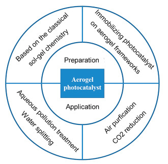
5.1. StatusPhotocatalysis has been considered as one of the most promising techniques that meet the requirement to solve energy and environment problems owing to its facial process and infinite green energy source [77]. Under light illumination, solar energy can be converted to chemical energy to realize environmental remediation and clean energy production over photocatalyst. However, most reported photocatalysts are in powder form, which has a strong tendency to agglomerate thus affecting the light absorption and pollutant adsorption. Moreover, powdery photocatalysts are difficult to recover, resulting in secondary pollutant. To overcome these weaknesses, aerogel photocatalyst with excellent monolithic properties exhibits great potential [78]. Aerogel is a monolithic pore material with extremely low densities, large specific surface areas and high porosity, which have nanoscale features with a total monolith size of several centimeters. Since aerogel photocatalyst is constructed by photocatalyst building blocks, it can be regarded as a bridge connecting the nano and macro worlds, in which the building blocks retain their photocatalytic properties while the 3D interaction of the photocatalyst building blocks creates new function. The porous structure of aerogel provides fast transport pathways to promote the absorption of pollutant while the photocatalyst building blocks absorb light and generate charge carriers to achieve solar energy conversion and environmental remediation. Fig. 6 reveals the structure and feature of aerogel photocatlayst.

|
Download:
|
| Fig. 6. Schematic diagram of aerogel photocatalyst. | |
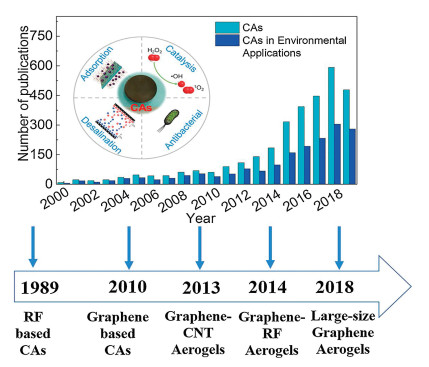
Over the past few years, it has been witnessed significant progress in aerogel photocatalyst. With the development of preparation technology, the synthetic method of aerogel photocatalyst has greatly evolved from the classical sol-gel route to the immobilizing photocatalyst in aerogel frameworks, which remarkable extended the aerogel photocatalyst family from traditional metal oxides and chalcogenides (TiO2 aerogel, ZrO2 aerogel, ZnS aerogel, WS2 aerogel and so on) to various composite aerogel photocatalyst (TiO2/graphene aerogel, g-C3N4/graphene oxide aerogel, MoS2/polyvinylpyrrolidone aerogel and so on) [79, 80]. And the application of aerogel photocatalyst has been developed from aqueous environmental remediation and water splitting to various gas-phase reaction, including NO oxidization, CO2 reduction and so on [81-83]. The summarize of preparation and application of aerogel photocatalyst is shown in Fig. 7.

|
Download:
|
| Fig. 7. Schematic diagram of the preparation and application of aerogel photocatalyst. | |
5.2. Current and future challenges
The main target of aerogel photocatalyst is to develop facile and sample synthesis route to obtain aerogel photocatalyst with excellent photocatalytic activity and mechanical strength. Therefore, there are three main challenges.
The first challenge is the preparation strategy. To date, the preparation strategy of aerogel photocatalyst can be divided into two routes. The one route is based on the classical sol-gel chemistry employing photocatalyst molecules or nano-scale units as building blocks [84]. However, since the lack of an effective sol-gel method for most photocatalyst, the type of aerogel photocatalyst has been significantly limited. On the other hand, owing to the building blocks connected with each other through the formation of weak hydrogen bond and van der Waals force, the obtained aerogel photocatalyst is fragile, limiting its practical application. The other route is immobilizing photocatalyst on aerogel frameworks, which employs the existent aerogel architecture as the monolithic scaffold [78]. This route is beneficial to develop aerogel photocatalyst covering almost all kinds of photocatalyst with desirable morphologies, and the synergistic effect between the photocatalyst and aerogel support can make a positive contribution to the photocatalytic activity. However, the widely used aerogel supports such as SiO2 and polymer aerogels are inert, which influence on the light absorption and charge carriers transfer. And despite the high conductivity of graphene aerogel can promote the electrons transfer, its high cost limits its application. Therefore, it is still a great challenge for the facile, sample and effective preparation route of aerogel photocatalyst.
The next challenge is the activity. Usually, there are three main factors affecting photocatalytic activity: (Ⅰ) pollutant adsorption; (Ⅱ) light absorption and charge carriers transfer; (Ⅲ) surface reaction [85]. The abundant porous structure of aerogel photocatalyst provides a large surface area which improves the pollutant adsorption and indirectly influences on final surface reaction. However, since most of aerogel photocatalyst is non-transparent, light energy can not be made full use of to generate charge carriers and the inert aerogel hinders the separation of photogenerated electrons and holes. As a result, despite the photocatalyst building blocks reveal remarkable photocatalytic activity in powder form, it will be greatly reduced when they are constructed to aerogel photocatalyst. Therefore, how to achieve excellent photocatalytic performance through the synergistic effect of monolithic structure and micro-component is still a worldwide challenge.
The third challenge is the reaction. The low density of aerogel photocatalyst makes it float on the solution, which hinders the light refraction and reflection in solution and improves the light utilization. Thus, most reports employ aerogel photocatalyst in the application of aqueous pollution degradation and water splitting. However, once in contact with the liquid, the strong capillary forces can destroy the porous and monolithic structure of aerogel photocatalyst, resulting in low photocatalytic activity even secondary pollutant [78, 84]. In comparison, small gas molecules are more accessible to the inner structure, taking full advantage of the active sites of aerogel photocatalyst. However, there are only a small amount of reports about NO oxidization and CO2 reduction over aerogel photocatalyst, and other gas reaction is rarely reported. On the other hand, different from the liquid reaction which can use the stirrer to promote the surface reaction, the driving force of gas molecules transfer to the active sites is usually only thermal motion, leading to a low gas concentration on the active sites and low photocatalytic activity. Therefore, it is still a challenge to expend the application field of aerogel photocatalyst.
5.3. Advances in science and technology to meet challengesTo meet the above-mentioned challenges, advances in both science and technology are urgent. Considering that aerogel photocatalyst has both micro- and macro- structures and features, the bottom-up strategies are beneficial for the design of aerogel photocatalyst. 3D printing technology has attracted enormous attention to the design and construction of materials in recent years [86]. Nowadays, the precision of 3D printing technology has been extended to the nanoscale with the great effort of generations of researchers. Since aerogel is regarded as the bridge of macro- and microworld, 3D printing technology can be considered as the designer and constructor of this bridge. Once the micro and macro structures of aerogel photocatalyst have been designed through computer software, 3D printer can bring it to real world. Therefore, the development of 3D printing technology provides important opportunity for the facile, sample and effective preparation route of aerogel photocatalyst. On the other hand, since the photocatalytic activity of aerogel photocatalyst is the synergistic effect of monolithic structure and micro component, theoretical calculation can predict the influence of monolithic structure and micro-component on the photocatalytic performance, including pollutant adsorption, light absorption, charge carriers transfer and surface reaction [87]. The cooperation with high-throughput reaction screening can help us to fast screen aerogel photocatalyst with highly efficient photocatalytic activity. Besides, the design of photocatalytic reactor reveals exciting potential to improve photocatalytic activity and extend photocatalytic reaction [88]. However, it should be noted that despite the above science and technology reveal great potential to meet the challenges of aerogel photocatalyst, there are still rare reports about them. The investigation of aerogel photocatalyst should be reinforced.
5.4. Concluding remarks and prospectsWith the enormous effort of researchers, aerogel photocatalyst has revealed the great potential in the application of environmental remediation and clean energy production. However, it still a great challenge to develop facile and efficient synthesis route to achieve aerogel photocatalyst with high photocatalytic activity and strong mechanical property. The progress of design strategies from bottom-up provides favorable opportunities for aerogel photocatalyst, such as 3D printing, theoretical calculation and so on. In the future, the development of aerogel photocatalyst should rely on the multi-disciplinary crossing research, including optics, electricity, fluidics, materials mechanics, etc. We believe that aerogel photocatalyst will bring a revolution of pore materials application with the advances in computational and experimental methodologies and the in-depth understanding of these materials.
5.5. AcknowledgmentsThis work is supported by the National Natural Science Foundation of China (No. U1232119), and the International Collaboration Project of Chengdu city (No. 2017-GH02-00014-HZ).
6. Carbon aerogels for environmental applicationsMingce Long*, Jie Miao
6.1. StatusTo deal with the global freshwater deficiency and environmental pollution, safe, reliable and cost-effective treatment technologies are urgently demanding [89]. Carbon aerogels (CAs), a series of carbonaceous materials having unique three-dimensional (3D) continuous porous structures, large mesopore volume, high surface areas and ultralow mass densities, provide new opportunities and strategies for such technologies. Although CAs were first obtained in as early as 1989 by using the polycondensation of resorcinol and formaldehyde, it has attracted great attentions only after the emergency of graphene-based CAs (Fig. 8) [90, 91]. Comparing with active carbon, the most widely used absorbent in environment cleanup, CAs are superior materials not only due to the inherent hierarchical porosity and better adsorption capacity, but also because of many special features including: (1) excellent conductivity of carbon-based scaffolds making it promising in electrical remediation techniques; (2) high flexibility in multifunctional applications by using CAs as the templates of heterocomponents; (3) other properties like high compressible strength, low thermal conductivity, lightweight, etc., expanding their applicable domains. Nowadays, CAs display great potentials in broad environment applications, including the removal of contaminants and antimicrobial in water and air, and desalination by capacity capacitive deionization (CDI) technology.

|
Download:
|
| Fig. 8. Number of publications during the past 20 years, along with the evolution pattern of CAs (date of search from Web of Science: 15 Sep. 2019). Reproduced with permission [90]. Copyright 2016, American Nano Society. | |
6.2. Current and future challenges
Although the studies on CAs for environmental applications have achieved big success in various domains, yet there are three challenges: (1) to understand the fundamental relationships between structure, properties and environmental performance of CAs materials; (2) to develop scalable synthetic approaches for advanced CAs that can meet the requirements on safety, reliability and affordability; (3) to bridge the gap between tests in lab-scales and scale-up applications in real environmental mediums.
6.3. Advances in science and technology to meet challengesMany studies contribute to increase the basic knowledge on the structure and properties dependent CAs performance [92]. Adsorption is the mostly explored performance, which is not only an efficient and facile approach to remove contaminants from water or air, but also the theoretical basis of multifunctional performance in environmental analysis, catalytic oxidation and electrosorption. Diverse contaminants, including heavy metal or radioactive metal ions, dyes, oils, antibiotics, and other concerning pollutants, can be removed from environment by adsorption, and the selectivity and capacity are mainly controlled by porous structures, surface functional groups and physicochemical properties of CAs. Adsorption of dissociated ionic pollutants can be improved by tuning surface charges to strengthen electrostatic interaction. CAs are generally negatively charged at neutral pHs and have better adsorption capacity for positively charged substance, like heavy metal ions and cation dyes. However, removal of anionic pollutants can be promoted by incorporating positively charged groups (e.g., amines) or polymers (e.g., polyethyleneimine or polydopamine). Simultaneously, the adsorption of pollutants containing aromatic rings can be influenced by π-π interaction, and hydrogen bonding interaction is involved in the removal of adsorbates containing carboxyl and hydroxyl groups. Moreover, the acidity and alkalinity of surface sites can influence the adsorption of chemicals. CAs have great potential to be used for uptake and selective catalytic reduction of CO2, a typical acidic chemical [93]. Creating basic sites from pyrolyzing a Schiff-base porous polymer aerogel or incorporating heteroatoms like nitrogen can significantly enhance CO2 capture capacity [94]. All such interactions in adsorption is relevant to the properties of surface sites.
The role of porous structures in ACs adsorption has also been explored in depth. Because gaseous pollutants have high mobility and small molecular sizes, adsorption for air purification is mainly governed by the porosity of the sub-nanometer pores. Such porous structures can be created by post-calcination in moderate reactive gases like steam or CO2, or chemical etching in strong acid like HNO3. Adsorption of hydrocarbons (oils and organic solvents) in CAs is dominated by physical processes. Superior oil removal capacity can be achieved by developing CAs with great specific surface area, large pore volumes and superhydrophobic and oleophilic surface. Many approaches have been proposed to modulate surface hydrophobicity of CAs, such as the increase of sp2 domains by reducing oxygen-containing functional groups or using CVD-process to obtain graphene foams, coating of hydrophobic components like fluoroalkylsilane, and tuning surface roughness by anchoring multiwall carbon nanotubes (CNTs) on graphene aerogels. In the contrary, better surface wettability are preferred to removal of soluble contaminants and ions, which can be improved by nitrogen doping or post-heating in air conditions. However, the changes of conductivity should be considered when CAs are used in electrochemical techniques.
Besides the high removal efficiency or reactivity of CAs for environment applications, the safety, reliability and affordability are more concerned about in the syntheses. To make CAs affordable in environmental applications, the cost of source materials should be decreased, and the scalable processes should be simplified. However, the foremost is to improve the recyclability of the materials. Although CAs can be easily recovered from water, regeneration of CAs in a cost-effective way is still a challenge and depends much on the comprehensive physical properties, such as compressible and tensile strength, elasticity, hardness and attrition resistance. The adsorbed organic liquids in CAs are ready to be squeezed out, yet the reliability is questionable due to the undesirable compressible strength. The strategies such as directional freezing of graphene hydrogel, or assembly of carbon nanotubes and graphene, are promising to obtain highly compressible [95]. Mechanical strength and elasticity can also be improved by adding reinforcers, like polyvinyl alcohol, glucose, dopamine and epoxy resin, which can form polymers to modulate the pore structures and surface functional groups.
CAs regeneration can also be realized by decomposing or selectively converting the adsorbates through catalytic redox reactions. Photocatalysis, Fenton reactions or other advanced redox reactions can take place accompanying with adsorption, when active sites or nanocatalysts were introduced into the scaffold of CAs. For example, impregnation of iron, cobalt and copper species can catalytic activate H2O2, persulfate and ozone, respectively, and produce reactive oxygen species for adsorbate degradation. Nitrogen doped CAs are metal free catalysts for persulfate activation. However, the pore structures and surface properties can be changed after a prolong stress of oxidation, and consequently the performance of the materials is deteriorated. Moreover, the instability of the supported metal oxides and the leaching of metal ions are major concerns in the long-term usage. A comprise can be reached by improving the chemical robustness of the carbonaceous materials and performing reactions under mild redox conditions. Recently, a promising regeneration method was reported by electrochemical desorption and degradation of adsorbates on graphene [96].
Although CAs exhibit excellent performance in many aspects, there are very few reports on the pilot environment applications. The retarded progress can be attributed to the following three reasons. Firstly, many reported results are inconsistent in the properties and performance. This can be understood by the variety in the nature of source materials and operation conditions. Secondly, it is still a challenge to process large-size CAs with homogeneous properties because the precursor aqueous graphene oxide has the inherent characteristic of macroscopically disordered liquid crystals [97]. Thirdly, the performance of CAs in the complicated matrix of real mediums is still questionable. The unfavorable influence includes the competitive adsorption of pervasive natural organic matters (NOM) in water, blocking surface sites by coexisting substance, destroying porous structures and altering surface properties by the harshness conditions (e.g., seawater), and so on.
6.4. Concluding remarks and prospectsWith the increased understanding on mechanistic influence of structure and properties, and with the enhanced capability in tailoring the materials, we can expect to develop more rational design and synthetic strategies and obtain desirable CAs. However, despite great promises of CAs for wide environment applications, following efforts are suggested to be taken to accelerate the progress. (1) Integration of current synthetic strategies should be attempted to obtain CAs for a specific application, and this also favors to develop scalable integrated processes. (2) Standardization should be considered in the engineering structures and properties of CAs, which is the way to break through the limitation on discrepancy, and also the prerequisite for the popularization and pilot applications of CAs. (3) Based on the features of CAs, the development of combined treatment processes, for example, combined with membrane technologies, is more promising to meet the requirements on industrial applications.
6.5. AcknowledgmentsFinancial supports from the National Natural Science Foundation of China (Nos. 21377084, 21876108) and National Key Research and Development Program of China (No. 2017YFE0195800) are gratefully acknowledged.
7. Porous metal oxide nanomaterials for electrocatalysisYuhai Dou*, Ding Yuan
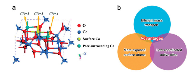
7.1. StatusElectrocatalysis, occurring on an electrode surface, effectively promotes the rate of an electrochemical reaction, which plays important roles in energy conversion technologies in modern society [98]. The most efficient electrocatalysts are always noble-metal-based ones containing Ru, Rh, Ir, Pd, Pt, Ag and Au due to their high catalytic activity and chemical stability. The scarcity and high cost of these electrocatalysts, however, severely impede their commercial applications. Earth-abundant metal oxides, such as Co3O4, NiO and MnO2, have been considered among themost promising alternatives because of their low cost and easily modulated electronic structures (Fig. 9a) [99]. The metal oxides in their pristine forms possess little catalytic activity, and therefore structural engineering is normally conducted, which lies at the heartof efficient catalyst design. Among different structure engineering strategies, pore generation is one of themost efficient and practical approach [100]. The creation of pores is especially facile when the dimensionality is reduced down to atomic scale, and therefore, various nanostructured metal oxides with different pore structures were synthesized and investigated [101, 102]. Compared with non-porous nanomaterials, porous ones demonstrate many advantages for electrocatalysis (Fig. 9b) [103, 104]. Firstly, the pores greatly promote the mass transport efficiency, including electrolyte diffusion, charge transfer and gas bubble detachment. Secondly, the pores increase the specific surface area with more surface atoms exposed for electrocatalysis. Thirdly, low-coordinated atoms are generated around the pore, which could serve as highly active sites to lower the catalytic energy barrier and enhance the catalytic activity. As a result, porous metal oxide nanomaterials for electrocatalysis have aroused tremendous research interest in the past decade.

|
Download:
|
| Fig. 9. (a) Crystal structure of Co3O4 near a pore (CN, coordination number). Reproduced with permission [99]. Copyright 2014, Royal Society of Chemistry. (b) Advantages of porous metal oxide nanomaterials for electrocatalysis. | |
7.2. Current and future challenges
The main function of pores is to facilitate mass transfer and create highly active sites, and two challenges need to be resolved for considerably enhanced electrocatalytic performance.
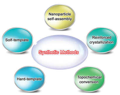
One is the synthetic method with desired pore structure (e.g., size and morphology) and density. It was reported that the pore size, density and structure play important roles in the catalytic activity, selectivity and durability as they determine the mass transfer efficiency, catalytic site activity and density. To date, there are mainly five methods to incorporate pores in metal oxide nanomaterials, including soft template, hard template, nanoparticle self-assembly, reinforced crystallization, and topochemical conversion (Fig. 10) [105]. These synthetic strategies have been proved to be efficient for pore creation, the precise control of the pore structure and density, however, is still a big challenge.

|
Download:
|
| Fig. 10. Synthetic methods for porous metal oxide nanomaterials. | |
The other one is the catalytic mechanism based on the newly created active sites. It is well known that the pores could not only decrease the coordination number of surrounding atoms but also alter the electronic states of nearby ones [102, 106]. The identification of the real catalytic active sites and the in-depth understanding of the relationship between electronic structure and catalytic activity/selectivity still require a great deal of effort.
7.3. Advances in science and technology to meet challengesTo create pores with desired structure and density, the templates should be rationally selected and designed, including its amount, location and removal process. The combination of soft-and hard-templates could also produce hierarchical porous structures offering multiple functionalities [100]. Moreover, previous works have demonstrated the importance of reaction conditions during the self-assembly, phase transformation and crystallization processes [105], and therefore the precise control of reaction conditions holds the key for the design of porous structures with proper pore size, high pore density, ordered distribution, etc.
To disclose the catalytic mechanism, many advanced characterization techniques have been developed [107], such as scanning transmission electron microscopy (STEM), scanning tunneling microscopy (STM), in situ X-ray photoelectron spectroscopy (XPS), in situ Raman spectroscopy, in situ X-ray absorption fine structure (XAFS) measurements, which could provide atomic-level insights into the pore structure-property relationships. In addition, density functional theory (DFT) calculations have been greatly developed in recent years, which could offer an accurate description of the correlation among electronic structure, intermediate binding energy and catalytic activity [108]. The combination of advanced characterization and calculation techniques could provide insight into the catalytic mechanism and guidance for the design of catalytically active porous structures.
7.4. Concluding remarks and prospectsPorous metal oxide nanomaterials for various electrocatalytic reactions have witnessed rapid development in the past decade, there is, however, still great room to make further improvement in terms of the pore structure and catalytic mechanism. We believe that with growing innovation in the synthetic method and continuing development in the characterization and theoretical calculation, the potential of porous metal oxide nanomaterials could be fully excavated, which will provide a major boost for the application in electrocatalysis and introduce some new opportunities into the fields of condensed matter physics, materials science, and chemistry in the near future.
7.5. AcknowledgmentsThis work is financially support by an Australian Research Council (ARC) Discovery Project (No. DP200100965) and a Griffith University Postdoctoral Fellowship.
Declaration of competing interestThe authors declare that there is no interest for this manuscript.
| [1] |
D. Feng, T. Lei, M.R. Lukatskaya, et al., Nat. Energy 3 (2018) 30-36. DOI:10.1038/s41560-017-0044-5 |
| [2] |
S. Bai, Y. Sun, J. Yi, et al., Joule 2 (2018) 2117-2132. DOI:10.1016/j.joule.2018.07.010 |
| [3] |
D.E. Mathew, S. Gopi, M. Kathiresan, et al., Electrochim. Acta 319 (2019) 189-200. DOI:10.1016/j.electacta.2019.06.157 |
| [4] |
S. Suriyakumar, S. Gopi, M. Kathiresan, et al., Electrochim. Acta 285 (2018) 355-364. DOI:10.1016/j.electacta.2018.08.012 |
| [5] |
C. Ye, Q. Qin, J. Liu, et al., J. Mater. Chem.A 7 (2019) 4998-5008. DOI:10.1039/C8TA11948A |
| [6] |
J.F. Wu, X. Guo, Small 15 (2019) 1804413-1804420. DOI:10.1002/smll.201804413 |
| [7] |
D. Sheberla, J.C. Bachman, J.S. Elias, et al., Nat. Mater. 16 (2017) 220-224. DOI:10.1038/nmat4766 |
| [8] |
J. Zheng, J. Tian, D. Wu, et al., Nano Lett. 14 (2014) 2345-2352. DOI:10.1021/nl404721h |
| [9] |
H. Jiang, X.C. Liu, Y. Wu, et al., Angew. Chemie. Int. Ed. 57 (2018) 3916-3921. DOI:10.1002/anie.201712872 |
| [10] |
S. Bai, X. Liu, K. Zhu, et al., Nat. Energy 1 (2016) 16094-16100. DOI:10.1038/nenergy.2016.94 |
| [11] |
B.M. Wiers, M.L. Foo, N.P. Balsara, et al., J. Am. Chem. Soc. 133 (2011) 14522-14525. DOI:10.1021/ja205827z |
| [12] |
S.S. Park, Y. Tulchinsky, M. Dincǎ, J. Am. Chem. Soc. 139 (2017) 13260-13263. DOI:10.1021/jacs.7b06197 |
| [13] |
Z. Wang, R. Tan, H. Wang, et al., Adv. Mater. 30 (2018) 1704436-1704443. DOI:10.1002/adma.201704436 |
| [14] |
S.M.J. Rogge, A. Bavykina, J. Hajek, et al., Chem. Soc. Rev. 46 (2017) 3134-3184. DOI:10.1039/C7CS00033B |
| [15] |
L. Oar-Arteta, T. Wezendonk, X. Sun, et al., Mater. Chem. Front. 1 (2017) 1709-1745. DOI:10.1039/C7QM00007C |
| [16] |
X. Sun, A.I.O. Suarez, M. Meijerink, et al., Nat. Commun. 8 (2017) 1680-1687. DOI:10.1038/s41467-017-01910-9 |
| [17] |
N.T. Suen, S.F. Hung, Q. Quan, et al., Chem. Soc. Rev. 46 (2017) 337-365. DOI:10.1039/C6CS00328A |
| [18] |
Y. Yang, M. Luo, W. Zhang, et al., Chem. 4 (2018) 2054-2083. DOI:10.1016/j.chempr.2018.05.019 |
| [19] |
R. Wang, H. Haspel, A. Pustovarenko, et al., ACS Energy Lett. 4 (2019) 2024-2031. DOI:10.1021/acsenergylett.9b01509 |
| [20] |
A. Fujishima, K. Honda, Nature 238 (1972) 37-38. DOI:10.1038/238037a0 |
| [21] |
L.E. Kreno, K. Leong, O.K. Farha, et al., Chem. Rev. 112 (2011) 1105-1125. DOI:10.1021/cr200324t |
| [22] |
X. Deng, R. Long, C. Gao, et al., Current Opinion Electrochem. 17 (2019) 114-120. DOI:10.1016/j.coelec.2019.05.010 |
| [23] |
W.W. Zhan, Q. Kuang, J.Z. Zhou, et al., J. Am. Chem. Soc. 135 (2013) 1926-1933. DOI:10.1021/ja311085e |
| [24] |
M. de Miguel, F. Ragon, T. Devic, et al., Chemphyschem 13 (2012) 3651-3654. DOI:10.1002/cphc.201200411 |
| [25] |
L. Zhang, P. Cui, H. Yang, et al., Adv. Sci. 3 (2016) 1500243-1500249. DOI:10.1002/advs.201500243 |
| [26] |
Q. Shen, X. Huang, J. Liu, et al., Appli. Catal. B:Environ. 201 (2017) 70-76. DOI:10.1016/j.apcatb.2016.08.008 |
| [27] |
Z. Peng, S.C. Abbas, J. Lv, et al., Int. J. Hydrogen Energy 44 (2019) 2446-2453. DOI:10.1016/j.ijhydene.2018.12.064 |
| [28] |
R. Ifraemov, R. Shimoni, W. He, et al., J. Mater. Chem.A 7 (2019) 3046-3053. DOI:10.1039/C8TA10483B |
| [29] |
J. Zhou, A. Zhou, L. Shu, et al., Appli. Catal. B:Environ. 226 (2018) 421-428. DOI:10.1016/j.apcatb.2017.12.065 |
| [30] |
N. Hüsing, U. Schubert, Angew. Chem. Int. Ed. 37 (1998) 22-45. DOI:10.1002/(SICI)1521-3773(19980202)37:1/2<22::AID-ANIE22>3.0.CO;2-I |
| [31] |
S.S. Kistler, Nature 127 (1931) 741-741. DOI:10.1038/127741a0 |
| [32] |
A.C. Pierre, G.M. Pajonk, Chem. Rev. 102 (2002) 4243-4265. DOI:10.1021/cr0101306 |
| [33] |
J.L. Mohanan, I.U. Arachchige, S.L. Brock, Science 307 (2005) 397-400. DOI:10.1126/science.1104226 |
| [34] |
N.C. Bigall, A.K. Herrmann, M. Vogel, et al., Angew. Chem. Int. Ed. 48 (2009) 9731-9734. DOI:10.1002/anie.200902543 |
| [35] |
I.U. Arachchige, S.L. Brock, Acc. Chem. Res. 40 (2007) 801-809. DOI:10.1021/ar600028s |
| [36] |
W. Liu, A.K. Herrmann, N.C. Bigall, et al., Acc. Chem. Res. 48 (2015) 154-162. DOI:10.1021/ar500237c |
| [37] |
C. Ziegler, A. Wolf, W. Liu, et al., Angew. Chem. Int. Ed. 56 (2017) 13200-13221. DOI:10.1002/anie.201611552 |
| [38] |
N. Gaponik, A.K. Herrmann, A. Eychmüller, J. Phys. Chem. Lett. 3 (2012) 8-17. DOI:10.1021/jz201357r |
| [39] |
S. Chu, Y. Cui, N. Liu, Nat. Mater. 16 (2016) 16-22. DOI:10.1038/nmat4834 |
| [40] |
M.K. Debe, Nature 486 (2012) 43-51. DOI:10.1038/nature11115 |
| [41] |
V.R. Stamenkovic, D. Strmcnik, P.P. Lopes, et al., Nat. Mater. 16 (2016) 57-69. DOI:10.1038/nmat4738 |
| [42] |
Z.W. Seh, J. Kibsgaard, C.F. Dickens, et al., Science 355 (2017) eaad4998. DOI:10.1126/science.aad4998 |
| [43] |
M. Shao, Q. Chang, J.P. Dodelet, et al., Chem. Rev. 116 (2016) 3594-3657. DOI:10.1021/acs.chemrev.5b00462 |
| [44] |
Y.J. Wang, N. Zhao, B. Fang, et al., Chem. Rev. 115 (2015) 3433-3467. DOI:10.1021/cr500519c |
| [45] |
Y. Nie, L. Li, Z. Wei, Chem. Soc. Rev. 44 (2015) 2168-2201. DOI:10.1039/C4CS00484A |
| [46] |
H.A. Gasteiger, S.S. Kocha, B. Sompalli, et al., Appl. Catal. B:Environ. 56 (2005) 9-35. DOI:10.1016/j.apcatb.2004.06.021 |
| [47] |
C. Chen, Y. Kang, Z. Huo, et al., Science 343 (2014) 1339-1343. DOI:10.1126/science.1249061 |
| [48] |
M. Escudero-Escribano, P. Malacrida, M.H. Hansen, et al., Science 352 (2016) 73-76. DOI:10.1126/science.aad8892 |
| [49] |
L. Bu, N. Zhang, S. Guo, et al., Science 354 (2016) 1410-1414. DOI:10.1126/science.aah6133 |
| [50] |
G. Wu, K.L. More, C.M. Johnston, et al., Science 332 (2011) 443-447. DOI:10.1126/science.1200832 |
| [51] |
J. Zhang, Z. Zhao, Z. Xia, et al., Nat. Nanotechnol. 10 (2015) 444-452. DOI:10.1038/nnano.2015.48 |
| [52] |
R. Silva, D. Voiry, M. Chhowalla, et al., J. Am. Chem. Soc. 135 (2013) 7823-7826. DOI:10.1021/ja402450a |
| [53] |
S. Guo, S. Zhang, S. Sun, Angew. Chem. Int. Ed. 52 (2013) 8526-8544. DOI:10.1002/anie.201207186 |
| [54] |
C. Zhang, S.Y. Hwang, A. Trout, et al., J. Am. Chem. Soc. 136 (2014) 7805-7808. DOI:10.1021/ja501293x |
| [55] |
T.Y. Ma, S. Dai, S.Z. Qiao, Mater. Today 19 (2016) 265-273. DOI:10.1016/j.mattod.2015.10.012 |
| [56] |
J. Speder, A. Zana, I. Spanos, et al., J. Power Sources 261 (2014) 14-22. DOI:10.1016/j.jpowsour.2014.03.039 |
| [57] |
O. Gröger, H.A. Gasteiger, J.P. Suchsland, J. Electrochem. Soc. 162 (2015) A2605-A2622. DOI:10.1149/2.0211514jes |
| [58] |
T. Mittermeier, A. Weiß, F. Hasché, et al., J. Electrochem. Soc. 164 (2016) F127-F137. |
| [59] |
C. Zhu, D. Du, A. Eychmüller, et al., Chem. Rev. 115 (2015) 8896-8943. DOI:10.1021/acs.chemrev.5b00255 |
| [60] |
W. Liu, A.K. Herrmann, D. Geiger, et al., Angew. Chem. Int. Ed. 51 (2012) 5743-5747. DOI:10.1002/anie.201108575 |
| [61] |
B. Cai, D. Wen, W. Liu, et al., Angew. Chem. Int. Ed. 54 (2015) 13101-13105. DOI:10.1002/anie.201505307 |
| [62] |
B. Cai, A. Dianat, R. Hübner, et al., Adv. Mater. 29 (2017) 1605254-1605262. DOI:10.1002/adma.201605254 |
| [63] |
W. Liu, D. Haubold, B. Rutkowski, et al., Chem. Mater. 28 (2016) 6477-6483. DOI:10.1021/acs.chemmater.6b01394 |
| [64] |
W. Liu, P. Rodriguez, L. Borchardt, et al., Angew. Chem. Int. Ed. 52 (2013) 9849-9852. DOI:10.1002/anie.201303109 |
| [65] |
S. Henning, L. Kühn, J. Herranz, et al., J. Electrochem. Soc. 163 (2016) F998-F1003. DOI:10.1149/2.0251609jes |
| [66] |
S. Henning, L. Kuhn, J. Herranz, et al., Electrochim. Acta 233 (2017) 210-217. DOI:10.1016/j.electacta.2017.03.019 |
| [67] |
D. Wen, W. Liu, D. Haubold, et al., ACS Nano 10 (2016) 2559-2567. DOI:10.1021/acsnano.5b07505 |
| [68] |
D. Wen, A.K. Herrmann, L. Borchardt, et al., J. Am. Chem. Soc. 136 (2014) 2727-2730. DOI:10.1021/ja412062e |
| [69] |
K.D. Gilroy, A. Ruditskiy, H.C. Peng, et al., Chem. Rev. 116 (2016) 10414-10472. DOI:10.1021/acs.chemrev.6b00211 |
| [70] |
L. Wu, A. Mendoza-Garcia, Q. Li, et al., Chem. Rev. 116 (2016) 10473-10512. DOI:10.1021/acs.chemrev.5b00687 |
| [71] |
M.V. Kovalenko, L. Manna, A. Cabot, et al., ACS Nano 9 (2015) 1012-1057. DOI:10.1021/nn506223h |
| [72] |
M.A. Boles, D. Ling, T. Hyeon, et al., Nat. Mater. 15 (2016) 141-153. DOI:10.1038/nmat4526 |
| [73] |
L. Zhang, L.T. Roling, X. Wang, et al., Science 349 (2015) 412-416. DOI:10.1126/science.aab0801 |
| [74] |
H.H. Li, S.Y. Ma, Q.Q. Fu, et al., J. Am. Chem. Soc. 137 (2015) 7862-7868. DOI:10.1021/jacs.5b03877 |
| [75] |
B. Cai, R. Hübner, K. Sasaki, et al., Angew. Chem. Int. Ed. 57 (2018) 2963-2966. DOI:10.1002/anie.201710997 |
| [76] |
B. Cai, K. Akkiraju, W.P. Mounfield, et al., Chem. Mater. 31 (2019) 9424-9429. |
| [77] |
A. Fujishima, T.N. Rao, D.A. Tryk, J. Photoch. Photobio. C:Photoch. Rev. 1 (2000) 1-21. DOI:10.1016/S1389-5567(00)00002-2 |
| [78] |
W. Wan, R. Zhang, M. Ma, et al., J. Mater. Chem.A 6 (2018) 754-775. DOI:10.1039/C7TA09227J |
| [79] |
B. Qiu, M. Xing, J. Zhang, J. Am. Chem. Soc. 136 (2014) 5852-5855. DOI:10.1021/ja500873u |
| [80] |
Q. Wang, X. Zhang, R. Lv, et al., J. Mater. Chem. A 4 (2016) 12387-12391. DOI:10.1039/C6TA03642B |
| [81] |
R. Zhang, M. Ma, Q. Zhang, et al., Appli. Catal. B:Environ. 235 (2018) 17-25. DOI:10.1016/j.apcatb.2018.04.061 |
| [82] |
S.K. Shahi, N. Kaur, V. Singh, Appl. Surf. Sci. 360 (2016) 953-960. DOI:10.1016/j.apsusc.2015.11.092 |
| [83] |
F. Rechberger, M. Niederberger, Mater. Horiz. 4 (2017) 1115-1121. DOI:10.1039/C7MH00423K |
| [84] |
F. Rechberger, M. Niederberger, Nanoscale Horiz. 2 (2017) 6-30. DOI:10.1039/C6NH00077K |
| [85] |
K.Q. Lu, X. Xin, N. Zhang, et al., J. Mater. Chem. A 6 (2018) 4590-4604. DOI:10.1039/C8TA00728D |
| [86] |
Q. Zhang, F. Zhang, S.P. Medarametla, et al., Small 12 (2016) 1702-1708. DOI:10.1002/smll.201503524 |
| [87] |
Y. Li, Y.L. Li, B. Sa, et al., Catal. Sci. Technol. 7 (2017) 545-559. DOI:10.1039/C6CY02178F |
| [88] |
F. Rechberger, M. Niederberger, Mater. Horiz. 4 (2017) 1115-1121. DOI:10.1039/C7MH00423K |
| [89] |
P.J.J. Alvarez, C.K. Chan, M. Elimelech, et al., Nat. Nanotechnol. 13 (2018) 634-641. DOI:10.1038/s41565-018-0203-2 |
| [90] |
P. Hu, B. Tan, M. Long, Nanotechnol. Rev. 5 (2016) 23-39. |
| [91] |
Y. Xu, K. Sheng, C. Li, et al., ACS Nano 4 (2010) 4324-4330. DOI:10.1021/nn101187z |
| [92] |
N. Yousefi, X. Lu, M. Elimelech, et al., Nat. Nanotechnol. 14 (2019) 107-119. DOI:10.1038/s41565-018-0325-6 |
| [93] |
S. Chowdhury, R. Balasubramanian, Prog. Mater. Sci. 90 (2017) 224-275. DOI:10.1016/j.pmatsci.2017.07.001 |
| [94] |
H. Li, J. Li, A. Thomas, et al., Adv. Func. Mater. 29 (2019) 1904785-1904794. |
| [95] |
H. Sun, Z. Xu, C. Gao, Adv. Mater. 25 (2013) 2554-2560. DOI:10.1002/adma.201204576 |
| [96] |
M. Pan, C. Shan, X. Zhang, et al., Environ. Sci. Technol. 52 (2017) 739-746. |
| [97] |
H. Yang, Z. Li, B. Lu, et al., ACS Nano 12 (2018) 11407-11416. DOI:10.1021/acsnano.8b06380 |
| [98] |
Y. Kang, P. Yang, N.M. Markovic, et al., Nano Today 11 (2016) 587-600. DOI:10.1016/j.nantod.2016.08.008 |
| [99] |
M.S. Faber, S. Jin, Energy Environ. Sci. 7 (2014) 3519-3542. DOI:10.1039/C4EE01760A |
| [100] |
W. Li, J. Liu, D. Zhao, Nat. Rev. Mater. 1 (2016) 16023-16040. DOI:10.1038/natrevmats.2016.23 |
| [101] |
Y. Ren, Z. Ma, P.G. Bruce, Chem. Soc. Rev. 41 (2012) 4909-4927. DOI:10.1039/c2cs35086f |
| [102] |
Y. Sun, S. Gao, F. Lei, et al., Chem. Sci. 5 (2014) 3976-3982. DOI:10.1039/C4SC00565A |
| [103] |
Y. Wang, H. Arandiyan, J. Scott, et al., J. Mater. Chem. A 5 (2017) 8825-8846. DOI:10.1039/C6TA10896B |
| [104] |
J. Qi, W. Zhang, R. Cao, ChemCatChem 10 (2018) 1206-1220. DOI:10.1002/cctc.201701637 |
| [105] |
Y. Ren, Z. Ma, P.G. Bruce, Chem. Soc. Rev. 41 (2012) 4909-4927. DOI:10.1039/c2cs35086f |
| [106] |
Y. Dou, T. Liao, Z. Ma, et al., Nano Energy 30 (2016) 267-275. DOI:10.1016/j.nanoen.2016.10.020 |
| [107] |
H. Jin, C. Guo, X. Liu, et al., Chem. Rev. 118 (2018) 6337-6408. DOI:10.1021/acs.chemrev.7b00689 |
| [108] |
Z.W. Seh, J. Kibsgaard, C.F. Dickens, et al., Science 355 (2017) 4998-5010. DOI:10.1126/science.aad4998 |