 2019, Vol. 30


b Institute of Advanced Synthesis, School of Chemistry and Molecular Engineering, Jiangsu National Synergetic Innovation Center for Advanced Materials, Nanjing Tech University, Nanjing 211816, China
Rechargeable lithium ion batteries (LIBs) currently are regarded as one of the most promising energy storage strategies for practical electric vehicles and hybrid electric vehicles throughout the world [1-6]. For LIBs, anode materials are critical to determine the overall performance and so have receiveddramatically increasingattention.
Intensive explorations have been focusing on Sn, Sb and Si based materials as an alternative to currently used commercial graphite anode for LIBs in recent years [5]. Among of them, metallic Sn or Sn based composites are stable, inexpensive and earth abundant materials and have been actively explored as LIB anodes. Generally, currently reported Sn based anode materials for LIBs could be classified into three categories: metal Sn, SnOx and tin trinary oxides [7-9]. Among of them, Li2SnO3 exhibits high theoretical capacity of approximately 653 mAh/g, which is much higher than that of graphite (372 mAh/g). However, the Li2SnO3 suffers from substantial volume change and particle agglomeration during the charge/discharge process, which results in dramatically capacity decrease and poor rate performance [10-12]. In order to solve the problem of volume expansion during alloying reaction, some strategies have been taken, such as reducing the size of materials [13], compounding with carbon-based materials [10, 11]. Zhang et al. [13] prepared Li2SnO3 by a sol–gel route and a solid-state reaction route. Results showed the sol-gel derived Li2SnO3 with uniform nano-sized particles (200–300 nm) can delivera betterreversible capacity than that with large agglomerates prepared from the solid-state reaction route. By combining Li2SnO3 with carbon-based materials, the composites can greatly improve the electrochemical performance of the electrodes. Wang et al. [12] synthesized graphene supported Li2SiO3/Li2SnO3 anode material for lithium ion batteries. Graphene could effectively serve as a matrix to buffer volume expansion.
As we all know, doping metal ions can have a direct effect on the ionic/electronic conductivity and structural stability of electrode materials during the electrochemical cycle. In view of the excellent electrical conductivity of silver, Ag+ has been doped into a number of electrode materials (e.g., Li4Ti5O12, V6O13, Li2ZnTi3O8) to improve their electrochemical performances [14-16]. Additionally, Agdoping also has been utilized to fabricate enhanced photocatalytic materials. Kudo et al. reported AgLi1/3Sn2/3O2 as photocatalysts from layered Li2SnO3 treated by molten AgNO3 [17]. To our knowledge, there has been no report on the influence of Ag-doping on the electrochemical behavior of Li2SnO3.
In this study, in view of the excellent electrical conductivity of silver and the ionic radius of Ag+ similar to that of lithium ion, we synthesized AgLi1/3Sn2/3O2 by facile molten salt method using AgNO3 as molten salt and comprehensively investigated its electrochemical performance in comparison to Li2SnO3. Ex situ XRD analysis was used to reveal electrochemical reaction mechanism between AgLi1/3Sn2/3O2 and Li. The synthesis details and measurement method of electrochemical performance can be found in Supporting information.
Li2SnO3 was firstly prepared by a conventional high temperature solid state synthesis, and then Ag-doped Li2SnO3 samples with different Ag content were obtained by molten AgNO3 treatment of Li2SnO3 through changing feed ratio of AgNO3 to Li2SnO3. Ag0.75-LSO and Ag0.25-LSO (LSO represents Li2SnO3) stands for the samples whose molar ratios of AgNO3 to overall feed are 0.75 and 0.25, respectively. The crystal structures are determined by X-ray diffraction (XRD) measurements and the results are shown in Fig. 1. It is observed that the peaks of Li2SnO3 can be perfectly assigned to monoclinic Li2SnO3 phase (JCPDS No. 031-0761) with symmetry of C2/c space group where a layered structure with Li layers and LiSn2 layers alternatively filled in oxygen stacking lattice and no any peak from impurity is detected. For Ag0.75-LSO sample (labeled by blue line), its XRD pattern is clearly not consistent with that of Li2SnO3, but it well agrees with that of AgCrO2 (JCPDS No. 032-1001) (a delafossitetype compound) and shifts to a lower angle than that of AgCrO2 [17]. The ionic radii of Cr3+, Li+ and Sn4+ are 0.615, 0.76 and 0.69 Å, respectively [18]. According to Bragg formula, the shift to a smaller angle is reasonable due to the ionic radii of Li+ and Sn4+ are larger than that of Cr3+. In addition, elemental analysis of Ag0.75-LSO was conducted by EDX and the corresponding result was shown in Fig. S1 (Supporting information). The molar ratio of Ag to Sn was determined to be 1.0:0.6 shown in Table S1 (Supporting information). It is concluded that Ag0.75-LSO sample is a delafossite-type compound and is obtained after the Li layers of Li2SnO3 are completely replaced by silver ions via ion exchange method, and so the chemical formula of Ag0.75-LSO sample is verified to be AgLi1/3Sn2/3O2 according to the literature [17]. As for the Ag0.25-LSO sample, it is clearly observed that the XRD pattern contains that of both Li2SnO3 and Ag0.75-LSO, indicating that Ag+ completely converts one part of Li2SnO3 into AgLi1/3Sn2/3O2 and the other part of Li2SnO3 is unchanged. It is worth pointing out that from powder XRD patterns of all samples, we observe the superstructure peaks arising from honeycomb ordering in LiSn2 slabs in the range of 18°~22°, which suggests ordered arrangement of Li and Sn in LiSn2 slabs along the monoclinic c axis of layered oxides [19, 20]. This also shows from the side that the structure of the transition metal layer is not destroyed, and only Li ions in the lithium layers are replaced by Ag ions according to reaction (1).

|
Download:
|
| Fig. 1. XRD patterns for LSO, Ag0.25-LSO and Ag0.75-LSO. | |

|
(1) |
Figs. 2a–c show SEM morphological features of Li2SnO3, Ag0.25- LSO and Ag0.75-LSO, respectively. All the images display non-uniform particles with a wide size distribution. Li2SnO3 particles in Fig. 2a display a wide size range from 150 nm to 1000 nm. SEM images reveal that the particle size of samples after ion exchange is similar to that of Li2SnO3, as shown in Figs. 2b and c, implying that the framework of the crystal structure of the Li2SnO3 starting material is maintained. The corresponding illustration of crystal structure is showed in Fig. 2d. As shown in the inset of Fig. 2c, it is noteworthy that the particle morphology of Ag0.75-LSO transfers to lamellar stacking from the block stacking of Li2SnO3, which is attributed to the replacement of Li+ in the lithium layers by Ag+. It is well known that the layered structure can shorten the transmission path of lithium ions and thus promote the transferring of lithium ions [21]. In addition, introducing Ag+ may increase the conductivity of the material, and thus accelerate the electron transfer. As a result, we speculate that the Ag0.25-LSO and Ag0.75-LSO samples possess better electron and Li+ transportation capability compared with Li2SnO3.

|
Download:
|
| Fig. 2. SEM morphologies of (a) Li2SnO3, (b) Ag0.25-LSO and (c) Ag0.75-LSO; (d) Schematic illustration of crystal structure evolutions of Li2SnO3 before and after the ion exchange of Li+ for Ag+. | |
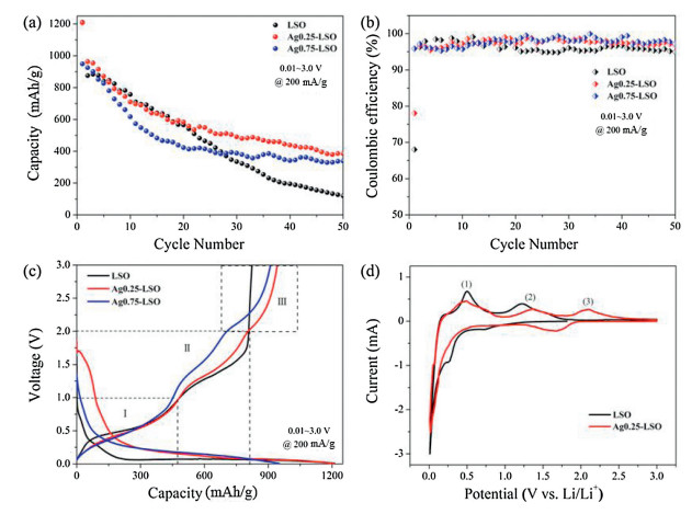
In order to evaluate their electrochemical performances, the above three materials are all constructed to Li half cells and their galvanostatic cycling tests are carried out in the voltage window of 0.01–3.0 V at 200 mA/g. Fig. 3a shows their cycling performance. The initial discharge capacity for LSO, Ag0.25-LSO and Ag0.75-LSO are 1210, 1208 and 950 mAh/g, respectively. While after 50 cycles, the remaining capacities are 120, 385 and 339 mAh/g for LSO, Ag0.25-LSO and Ag0.75-LSO samples, respectively, giving rise to their corresponding capacity retention of 10%, 32% and 36%. The Li2SnO3 sample suffers from rapid attenuation of the reversible capacity upon cycling and almost 90% loss of capacity at 50th cycle. Apparently, the cycle performance of samples after ion-exchange becomes better. In addition, the initial coulombic efficiency also become higher after ion-exchange and Fig. 3b shows the corresponding values are 68%, 78% and 96% for LSO, Ag0.25-LSO and Ag0.75-LSO samples, respectively. Beyond that, the rate capability of LSO and Ag0.75-LSO is shown in Fig. S2 (Supporting information). The specific capacity of Ag0.75-LSO is higher than that of LSO at high current density of 2 A/g and 5 A/g, and the specific capacity of Ag0.75-LSO recovered to 400 mAh/g when the current recovered from 5 A/g to 200 mA/g. These electrochemical data unambiguously demonstrate that introducing Ag+ into lithium layers of Li2SnO3 helps to improve its coulombic efficiency, cycling stability and rate capability.

|
Download:
|
| Fig. 3. (a) Cycling performance, (b) coulombic efficiency and (c) initial charge-discharge profiles taken at 200 mA/g for Li2SnO3, Ag0.25-LSO and Ag0.75-LSO; (d) CV curves of initial three cycles conducted at a scan rate of 0.1 mV/s for Li2SnO3 and Ag0.25-LSO. | |
As is well known, the conversion reaction of Sn-based materials is highly irreversible which results in the irreversible capacity loss during the first discharge - charge cycle and thus leads to low coulombic efficiency [9, 22]. However, the irreversibility of the conversion reaction is remarkably improved after replacing Li+ in the lithium layers of Li2SnO3 by Ag+. As shown in Fig. 3c, the first charge capacity is divided into three parts: part Ⅰ below 1.0 V, part Ⅱ in a range of 1.0–2.0 V and part Ⅲ beyond 2.0 V. The parts Ⅰ and Ⅱ of Li2SnO3 usually correspond to the de-alloying of Li4.4Sn and the oxidation of Sn, respectively [23]. In order to identify their electrochemical reactions for the first charge cycle, we collected the cyclic voltammetry (CV) profiles of LSO and Ag0.25-LSO at a scanning rate of 0.1 mV/s and their results are shown in Fig. 3d. It is observed that the major oxidation peaks for LSO and Ag0.25-LSO are positioned close to each other, one is at ~0.50 V (1) corresponding to the dealloying of LixSn and the other is at ~ 1.26 V (2) corresponding to the oxidation of Sn [24, 25]. It is worth reminding that the part Ⅲ of Li2SnO3 almost does not contribute to capacity. And interestingly enough, it is observed that the part Ⅲ of samples after ion exchange exists obvious capacity contribution compared with Li2SnO3. So where does the extra capacity beyond 2.0 V come from?
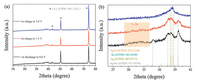
In order tofigure out the origin of extra capacity contribution in the Ag0.75-LSO, we use Ag0.75-LSO to carry out the ex situ XRD measurements on discharged and charged electrodes. Fig. 4a presents the XRDprofilesof Ag0.75-LSO after initially discharging to 0.0 V, charging to 1.5 V and 3.0 V casting on Cu foil. Evidently, the XRD peaks of discharged/charged products are hidden by signals of Cu foil, resulting from the strong diffraction peaks of Cu current collector (JCPDS No. 001-1242). To clearly observe diffraction peaks of discharged and charged products, we amplify the diffraction angle region of 26°~42° as displayed in Fig. 4b. After the electrode completely discharges to 0.0 V, the XRD pattern of Ag0.75-LSO completely disappears, and meanwhile new diffraction peaks appear in the range of 34°~40°, ascribing to the Ag (JCPDS No. 087-0717) and Ag3Sn (JCPDS No. 071-0530) generated from the reduction of Ag+ and alloying reaction between Ag+ and Sn, respectively. Besides, the broad peak in the range of 29-34° can be assigned to Li4.4Sn (highlight by light red) from the alloying reaction between Li+ and Sn [23]. Upon recharging back to 1.5 V, the diffraction peaks from Ag3Sn and Li4.4Sn become weaker, indicating that de-alloying reaction during charge process. Noteworthy that the diffraction peaks of Ag hardly change, implying that the voltage of 1.5 V is not enough to oxidize Ag. While when recharging to 3.0 V, a new peak appears at 38.5°, ascribing to Ag2O (JCPDS No. 072-2108) generated from the oxidation of Ag. The above discussion regarding to initial charge process from 1.5 V to 3.0 V well explains the reason why the samples after ion exchanging show extra capacity in the range of 2.0–3.0 V (Part Ⅲ). Meanwhile, the peaks of Li4.4Sn and Ag3Sn completely disappear, which is ascribed to completion of the de-alloying process. Based on the ex situ XRD results, it is speculated that the electrochemical reaction mechanism of Ag0.75-LSO (chemical formula, AgLi1/3Sn2/3O2) with Li is expressed as the following:

|
Download:
|
| Fig. 4. (a) XRD patterns for the discharged and charged Ag0.75-LSO; (b) enlarged view in the range of 26°~42°. | |
Discharged: AgLi1/3Sn2/3O2 + Li+ + e- → Li4.4Sn + Ag3Sn + Ag + Li2O
Charged: Li4.4Sn + Ag3Sn + Ag - e- → Sn + Ag+ + Li+
In conclusion, AgLi1/3Sn2/3O2 was successfully synthesized by the molten salt method using AgNO3 as molten salt and employed as anode material for LIB for the first time. It is found that the incorporation of Ag into the lithium layer of Li2SnO3 is beneficial to the Li+ and electron kinetic diffusion, which is attributed to the lamellar stacking morphology of AgLi1/3Sn2/3O2 and the excellent electrical conductivity of Ag itself. Compared with Li2SnO3, AgLi1/3Sn2/3O2 exhibits better electrochemical performance in terms of capacity, coulombic efficiency, rate capability and cycling stability. Importantly, the electrochemical working mechanism of AgLi1/3Sn2/3O2 with Li is uncovered based on the ex situ XRD measurement. Introducing Ag+ into the lithium layer of layered Li2SnO3 and the understanding of working mechanism will direct the development of high performance layer oxides materials for LIBs in future.
AcknowledgmentsThis work was supported by Natural Science Foundation of Jiangsu Province of China (No. BK20170982) and the National Natural Science Foundation of China (No. 51601080).
Appendix A. Supplementary dataSupplementary material related to this article can be found, in the online version, at doi:https://doi.org/10.1016/j.cclet.2019.04.019.
| [1] |
M. Armand, J.M. Tarascon, Nature 451 (2008) 652-657. DOI:10.1038/451652a |
| [2] |
B. Dunn, H. Kamath, J.M. Tarascon, Science 334 (2011) 928-935. DOI:10.1126/science.1212741 |
| [3] |
H. Yuan, L. Kong, T. Li, et al., Chin. Chem. Lett. 28 (2017) 2180-2194. DOI:10.1016/j.cclet.2017.11.038 |
| [4] |
M. Hong, J. Li, W. Zhang, Q. Zhang, Energy Fuels 32 (2018) 6371-6377. DOI:10.1021/acs.energyfuels.8b00454 |
| [5] |
F. Lu, S.Z. Liu, G.F. Zeng, J.M. Li, Y. Yang, J. Electrochem. Soc. 165 (2018) A2897-A2903. DOI:10.1149/2.0201811jes |
| [6] |
L. Hao, L. Long, P. Kunal, et al., J. Phys. Chem. C 122 (2018) 2712-2716. DOI:10.1021/acs.jpcc.7b10974 |
| [7] |
S.L. Yang, B.H. Zhou, M. Lei, et al., Chin. Chem. Lett. 26 (2015) 1293-1297. DOI:10.1016/j.cclet.2015.05.051 |
| [8] |
Z. Zhang, Y. Hou, S. Zhang, et al., Chin. Chem. Lett. 29 (2018) 1656-1660. DOI:10.1016/j.cclet.2018.06.017 |
| [9] |
M.V. Reddy, G.V. Subba Rao, B.V. Chowdari, Chem. Rev. 113 (2013) 5364-5457. DOI:10.1021/cr3001884 |
| [10] |
Q.F. Wang, Y. Huang, J. Miao, Y. Wang, Y. Zhao, Appl. Surf. Sci. 258 (2012) 6923-6929. DOI:10.1016/j.apsusc.2012.03.136 |
| [11] |
Y. Zhao, Y. Huang, Q. Wang, et al., J. Appl. Electrochem. 43 (2013) 1243-1248. DOI:10.1007/s10800-013-0612-8 |
| [12] |
Q.F. Wang, S. Yang, J. Miao, et al., Appl. Surf. Sci. 469 (2019) 253-261. DOI:10.1016/j.apsusc.2018.11.055 |
| [13] |
D.W. Zhang, S.Q. Zhang, Y. Jin, et al., J. Alloys Compd. 415 (2006) 229-233. DOI:10.1016/j.jallcom.2005.05.053 |
| [14] |
S.H. Huang, Z.Y. Wen, X.J. Zhu, Z.H. Gu, Electrochem. Commun. 6 (2004) 1093-1097. DOI:10.1016/j.elecom.2004.08.013 |
| [15] |
J.Y. He, W.M. Wang, Z.G. Zou, F. Long, Z.Y. Fu, Ionics 20 (2014) 1063-1070. DOI:10.1007/s11581-013-1049-0 |
| [16] |
H.Q. Tang, Z.Y. Tang, C.Q. Du, F.C. Qie, J.T. Zhu, Electrochim. Acta 120 (2014) 187-192. DOI:10.1016/j.electacta.2013.12.090 |
| [17] |
Y. Hosogi, H. Kato, A. Kudo, J. Mater. Chem. 18 (2008) 647-653. DOI:10.1039/B715679K |
| [18] |
D.R. Shannon, Acta Crystallogr. Sect. A 32 (1976) 751-767. DOI:10.1107/S0567739476001551 |
| [19] |
J. Bréger, M. Jiang, N. Dupré, et al., J. Solid State Chem. 178 (2005) 2575-2585. DOI:10.1016/j.jssc.2005.05.027 |
| [20] |
B. Mortemard de Boisse, G. Liu, J. Ma, et al., Nat. Commun. 7 (2016) 11397. DOI:10.1038/ncomms11397 |
| [21] |
Y. Masatomo, I. Mitsuru, I. Yoshiyuki, M. Yukio, J. Am. Chem. Soc. 127 (2005) 3491-3495. DOI:10.1021/ja0449224 |
| [22] |
L. Weng, J. Zhou, R. Cai, Int. J. Mech. Sci. 141 (2018) 245-161. DOI:10.1016/j.ijmecsci.2018.04.013 |
| [23] |
I.A. Courtney, J. Electrochem. Soc. 144 (1997) 2045-2052. DOI:10.1149/1.1837740 |
| [24] |
W. Dong, J. Xu, C. Wang, et al., Adv. Mater. 29 (2017) 1700136. DOI:10.1002/adma.201700136 |
| [25] |
F. Belliard, J.T.S. Irvine, Ionics 7 (2001) 16-21. DOI:10.1007/BF02375462 |