 2019, Vol. 30


b Key Laboratory for Organic Electronics & Information Displays(KLOEID) and Institute of Advanced Materials, Nanjing University of Posts & Telecommunications, Nanjing 210023, China;
c Shaanxi Institute of Flexible Electronics(SIFE), Northwestern Polytechnical University(NPU), Xi'an 710072, China
Electron-deficient acceptor materials are important components of organic electronic devices [1-8]. Among those devices, organic light-emitting diodes (OLEDs) have been widely investigated on self-luminescent displays and even ascendant flexible displays [9-16] with wide viewing angle, high efficiency, low power consumption on the basis of organic materials especially for acceptor materials. Acknowledged to us, the transport of holes is faster than the transport of electrons in most organic semiconductors without charge transport balance leading to the insufficient excitons and decreased external quantum efficiency (EQE). In this situation, it is necessary to develop suitable electron injection materials (EIMs) between the transparent cathodes and electron transport layer (ETL) or emitting layer (EML) to optimize the charge injection and transport balance [17-22]. In recent years, electrode interface between the cathode and the adjacent organic layer for effective electron injection has been achieved by using kinds of EIMs containing alkali metals [23-25], alkali metal halides [26, 27], alkali metal carbonates, etc. [28, 29]. However, some EIMs were too active to be processed or performed in mild condition. Beside of those inorganic EIMs, some conjugated polymers including polyelectrolytes [30-39] and oligoelectrolytes [40] have been employed as EIMs to improve the performance of electroluminescence devices. Furthermore, some non-conjugated molecular systems including amide derivatives [41], smallmolecular zwitterions [42], sulfonium salts [43, 44], polyethylenimines [45-47], and tetraoctylammonium bromide [48] have also been applied as EIMs with limited electron affinity, LUMO energy level and structural adjustability.
Beside of that, small molecule π-acceptors have also been successfully used as EIMs [49-55] including widely-used but expensive and unsustainable tetracyano-p-quinodimethane (TCNQ, oxidation/Br2) [55] and hexaazatriphenylene-hexacabonitrile (HAT(CN)6) with deep LUMO energy levels, large electronic affinities [50-53]. However, their synthetic routines and thermal sublimation procedure are still not "green" or facile enough. In this situation, it is necessary to explore novel green acceptor materials via green-synthesis methods [56-61] with the advantages of cheap starting compounds, high yield, and facile purification process of wet-chemistry. Currently to our knowledge, no such acceptor azaacene has been reported as EIMs.
In this contribution, we designed and synthesized two electrondeficient cyanodiazafluorene derivatives (CAFs) including di- and tetra-cyanodiazafluorene (DCAF and TCAF) as presented in Scheme 1. Every DCAF molecule possesses only two cyano groups, but every TCAF molecule has four cyano groups instead. Both of them could be easily green-synthesized in green solvent such as ethanol with rather high yields > 85% per step. DCAF and TCAF are both soluble in common organic solvents and easily purified by washing, recrystallization or flash column chromatography. The electrochemical, thermal properties, film morphologies of two CAFs were fully characterized. Three systematic groups of OLED devices were fabricated with corresponding DCAF or TCAF as the EIMs.

|
Download:
|
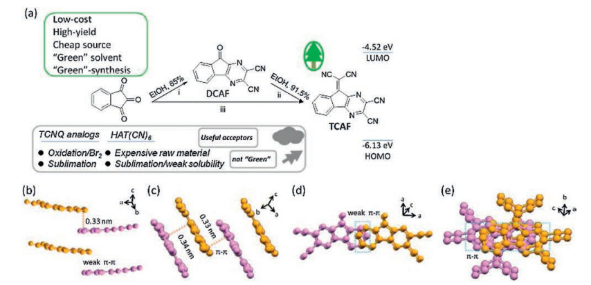
| Scheme 1. (a) The synthetic routes of DCAF and TCAF: (ⅰ) 1H-indene-1, 2, 3-trione, 2, 3-diaminomaleonitrile (DAMN), EtOH, refluxed, 10 h, 85.0% for DCAF; (ⅱ) DCAF, malononitrile, EtOH, refluxed, 10 h, 91.5% for TCAF; (ⅲ) 1, 2, 3-indantrione, DAMN, and EtOH, refluxed, 10 h; then malononitrile, refluxed, another 10 h. Packing modes of DCAF (b, d) and TCAF (c, e) in single crystals. | |
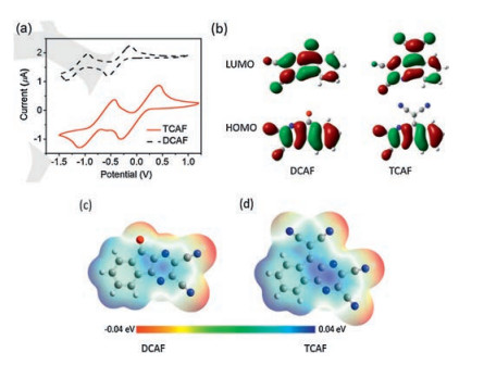
The synthetic routines for the designed DCAF and TCAF were outlined in Scheme 1 as a two-step procedure (ⅰ, ⅱ) and one-steptwo-stage procedure (ⅲ) with different reaction components. DCAF was synthesized from the cyclo-condensation between 1Hindene-1, 2, 3-trione and 2, 3-diaminomaleonitrile (DAMN) with a high yield of 85.0% (Scheme 1a, ⅰ). Then TCAF was obtained from the atom-economical Knoevenagel condensation between DCAF and malononitrile with an excellent 91.5% yield (Scheme 1a, ⅱ). This two-step procedure was carried out in green solvent ethanol and produced target CAF and water with high yield as atomeconomical green-synthesis [56-61]. Actually, TCAF could be directly synthesized by adding malononitrile into the mixed system of DCAF and DAMN after the first 10 h and then refluxed for another 10 h with similar high yield (Scheme 1a, ⅲ). Molecular structures of DCAF and TCAF were confirmed by 1H NMR spectroscopy and GC–MS consistent with that depicted in Scheme 1. Furthermore, high quality single crystals of DCAF and TCAF were obtained from the evaporation of corresponding dichloromethane solution. TCAF possesses cofacial π–π stacking [6, 7] within 0.33-0.34 nm (Schemes 1c and e). But DCAF took a partially π–π stacking within 0.33 nm (Schemes 1b and d). Beside of that, the electrostatic potentials of DCAF and TCAF were calculated by the density functional theory B3LYP/6–31 G(d) method (details in Supporting information). Both CAFs have similar electropositive centers on CAF backbone, but TCAF presented stronger electronegativity of four protuberances than another. It is implied that stronger electronic affinity of TCAF than that of DCAF could potentially modificate organic/metal interfaces (Figs. 1c and d).

|
Download:
|
| Fig. 1. (a) Cyclic voltammogram recorded for DCAF and TCAF; b) Wave functions for the HOMO and LUMO of DCAF and TCAF molecules, respectively; (c, d) Calculated electrostatic potentials of single molecule of DCAF and TCAF. | |
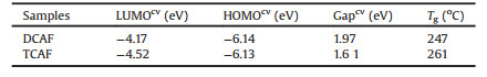
The electrochemical properties of DCAF and TCAF were investigated by cyclic voltammetry (CV) in Fig. 1. The LUMO energy levels of DCAF and TCAF were calculated to be -4.17 eV and -4.52 eV, respectively, according to the empirical equation LUMO = -[4.4 + Ere] [62-64] as listed in Table 1. The corresponding highest occupied molecular orbital (HOMO) energy level were calculated to be -6.14 eV, -6.13 eV (Fig. S4 in Supporting information), respectively. In Fig. 1b, the LUMO energy levels of DCAF and TCAF delocalized over the entire molecule including carbonyl, dicyanomethylene. While both HOMO energy levels delocalized on the CAF backbone. The thermogravimetric analysis (TGA) exhibited that DCAF and TCAF decomposed at 247 ℃ and 261 ℃ with 5% weight loss, respectively (Fig. S5 in Supporting information). It is indicated that DCAF and TCAF are stable enough and potentially suitable for electronic devices.
|
|
Table 1 Electrochemical and thermal characteristics of DCAF and TCAF. |
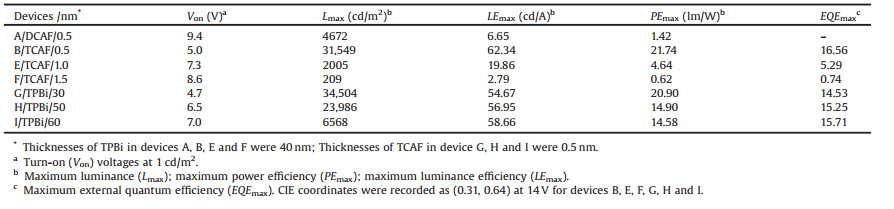
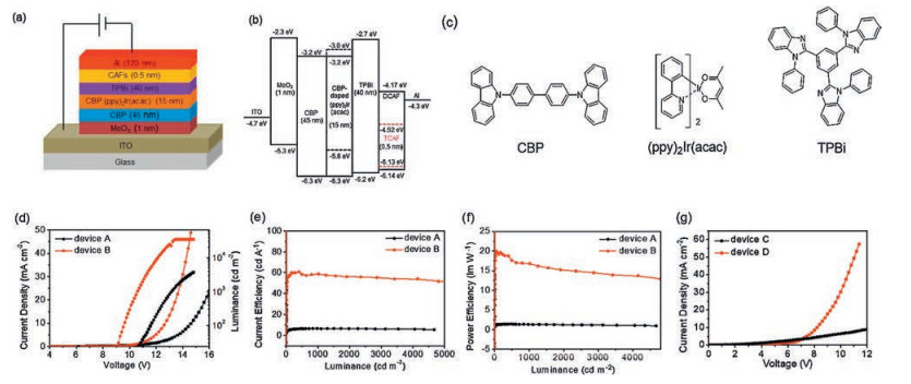
In order to disclose the electron injection ability of DCAF and TCAF, two primary devices were fabricated using DCAF and TCAF as the electron injection layer (EIL) with 0.5 nm thickness and TPBi as the ETL with 40 nm thickness. The corresponding configurations were designed as ITO/MoO3 (1 nm) [65] / CBP (45 nm) [66] / CBP:(ppy)2Ir(acac) (15 nm) [67] / TPBi (40 nm) [66] / CAFs (0.5 nm) / Al (120 nm) showed in Figs. 2a and b, and Table S1 (Supporting information). Figs. 2d-f and Table 2 showed the current density–voltage–luminance (J–V–L) and luminance efficiency–luminance (LE–L) characteristics and main parameters. Devices A and B with 0.5 nm thickness CAFs as the EIL exhibited different turn-on voltage (Von) (Von is defined as the voltage by luminance of 1 cd/m2). Obviously, the high Von of device A sharply decreased 0.54 times from 9.4 V to a lower Von as 5.0 V of device B. Especially, the maximum luminescence (Lmax) intensity of device Breached as high as 31, 549 cd/m2 which is 6.8 times than the Lmax (4672 cd/m2) of device A. Beside of that, the current density of device A and device B were 0.54, 7.1 mA/cm2 at 11 V, respectively. Meanwhile, the corresponding maximum luminance efficiency (LEmax) measured on device B was up to 62.34 cd/A, almost 9 times than that of device A (6.65 cd/A), the LEmax of device B is obviously greater than that of device A in contrast to the performance of standard device with Cs2CO3 as EIM (71.4 cd/A, Table S6 in Supporting information). This phenomenon [51, 68, 69] could be explained by the deeper LUMO and stronger electronic affinity of TCAF with four cyano groups inducing interface dipole effect with potential charge transfer at TPBi/TCAF/Al interfaces.
At the same luminance intensity of 4000 cd/m2 (Fig. 2e), the efficiencies could maintain 88.6%, 91.7% of LEmax (62.34 cd/A) when the LE of devices A and B reached 5.89 and 53.88 cd/A, respectively. As shown in Table 2, the maximum power efficiency (PEmax) of device B (21.74 lm/W) was much higher than that of device A (1.42 lm/W), which is almost 14 times than that of device A. The largest EQE belonged to device B as high as 16.56%. Furthermore, as showed in Fig. 2g and Table S2 (Supporting information), two electron-only devices (C and D) were fabricated and device D displayed larger current density than that of device C with Al. It was indicated that the lower driving voltage improved EL characteristics with higher LE, which demonstrating the better electron injection ability of TCAF than that of DCAF.

|
Download:
|
| Fig. 2. (a) Schematic configuration of devices A and B; (b) Energy level diagrams of devices A and B; (c) molecule structures of organic materials in devices A and B; (d) J–V–L characteristics of devices A and B; (e) LE–L characteristics of devices A and B; (f) PE–L characteristics of devices A and B; (g) L–V characteristics of DCAF/TCAF-based electrononly devices C and D. | |
|
|
Table 2 Three groups of device characteristics: Ⅰ. Devices A and B with different CAFs as EIM; Ⅱ. Devices B, E, and F with different thicknesses of TCAF; Ⅲ. Devices G, B, H and I with different thicknesses of TPBi (30, 40, 50, and 60 nm). |
Compared with device B, two more devices (E and F) have also been fabricated with 1.0 nm and 1.5 nm thick TCAF as EIM to further investigate the relationship between electron injection ability and thickness of TCAF (Fig. 3). The general configuration of devices E and F was ITO/MoO3 (1 nm)/CBP (45 nm)/CBP:Ir (ppy)2(acac) (8%, 15 nm)/TPBi (40 nm)/TCAF/Al (120 nm) (Fig. S8 and Table S3 in Supporting information). And device B possessed different TCAF thickness. Fig. 3 presented the J–V–L, and LE–L characteristics with the main parameters were shown in Table 2. Observed from J–V–L graph of device B (Figs. 2 and 3), when 0.5 nm thick TCAF as EIM, device B displayed good performance. But when the TCAF thickness increased to 1.0 nm and 1.5 nm in devices E and F, the Von increased to 7.3 V and 8.6 V, respectively. Their Lmax sharply decreased from 31, 549, 2005 to 209 cd/m2, respectively. The Lmax of device B was 15.7 and 150.9 times than that of devices E and F, respectively.
Following the increased voltage, the current density of device B reached a high level as 17.9 mA/cm2 which was 8 times than that of devices E and F (2.0 and 1.7 mA/cm2), respectively. Meanwhile, the corresponding LEmax measured on devices B, E, and F were recorded as 62.34, 19.86, and 2.79 cd/A, respectively. As shown in Fig. 3b and Table 2, when the thickness of TCAF increased, the LE–L curve slumped to a quite lower level and sharply decreased efficiency. It was indicated that the thicknesses of TCAF determined the electron injection ability. It was explained that charges could tunnel through the CAFs with only 0.5 nm thickness rather than thicker CAFs [70]. Device B exhibited a very good stability with the LE keeping at level of 57.8 cd/A which was 92.7% of the LEmax (62.34 cd/A) when luminance intensity was 4900 cd/m2. However, when the thickness of TCAF increased from 0.5 to 1 nm and 1.5 nm, the luminance curve immediately decreased bellow 250 cd/m2. As shown in the Fig. 4c, the best PEmax (21.47 lm/W) of device B was 16.8 and 34.6 times than that of device F (4.64 lm/W) and device G (0.62 lm/W), respectively. Fig. S12 (Supporting information) showed the EL spectra of device B and E driven at 14 V with the green light emission peaks at 523 nm. Accordingly, the EQE of device B (16.56%) was 3.1 and 22.4 times than that of device E (5.29%) and device F (0.74%), respectively. It was indicated that device parameters based on TCAF as EIM largely depended on the special thickness of 0.5 nm of interfacial modification layer for better performance.
As presented in Fig. S13 (Supporting information), the atomic force microscope (AFM) exhibited topographic images and phase images (5 μm×5 μm) of the vapor-deposited TCAF films under vacuum with gradually increased thickness from 0.5 nm, 1 nm to 1.5 nm on bare Si substrates. All the surface morphologies of three films possessed similar roughness and uniform surface without obvious grain dispersion. The morphologies were conducive to the interfacial modification and electron injection.
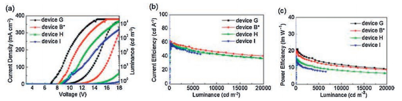
In order to further investigate the performance of OLEDs with TCAF as EIM, another series of devices were constructed by regulating the thicknesses of TPBi as ETL (Fig. 4). In contrast to device B with optimal thickness of TCAF (0.5 nm) and TPBi (40 nm), three more devices (G, H, and I) were fabricated by changing the thicknesses (30, 50 and 60 nm) of TPBi as ETL (Fig. S9 and Table S4 in Supporting information). As shown in Fig. 4a and Table 2, when the thickness of TPBi was 30 nm, device G displayed quite similar and slightly smaller Von of 4.7 V, higher Lmax of 34, 504 cd/m2, smaller LEmax of 54.67 cd/A, and decreased PEmax of 20.90 lm/W than that of device B. However, when the thickness of TPBi increased to 50 nm and 60 nm, devices H and I presented remarkably decreased parameters including Von, Lmax and PEmax (Table 2) except for LEmax and EQE. As depicted in Fig. 4b and Table 2, these two parameters of devices G, B, H, and I kept at the same level as 54.67, 62.34, 56.95, and 58.66 cd/A and 14.53, 16.56, 15.25 and 15.71% with gradually increased thicknesses of TPBi. The Lmax of device G reached 34, 504 cd/m2 larger than the value of devices B (31, 549 cd/m2) and H (23, 986 cd/m2). And it was also almost 5 times than the value of device I (6568 cd/m2). At 5000 cd/ m2, LE decreased to be 87.63, 92.60, 84.84, and 77.35% in contrast to their LEmaxwhile LEdescendedto47.91, 57.73, 48.32 and 45.35 cd/A relative to the LEmax of devices G, B, H and I, respectively (Table 2).

|
Download:
|
| Fig. 3. The (a) J–V–L characteristics of devices B, E, and F; (b) LE–L characteristics of devices B, E, and F; (c) PE–L characteristics of devices B, E, and F. * Means the curves of device B were presented for comparison. | |

|
Download:
|
| Fig. 4. The (a) J–V–L characteristics of devices G, B, H and I; (b) LE-L characteristics of devices G, B, H, and I; (c) PE–L characteristics of devices G, B, H and I. *Means the curves of device B were presented for comparison. | |
In summary, the first application of "green"-synthesized, atomeconomical acceptorazaacene TCAF was successfullycarried out as EIM in OLEDs with good device performance than that of DCAF as EIM. It is reasonable to distribute the better performance of device B with TCAF as EIM to the stronger electron injection and interfacial modification ability originating from the deeper LUMO energy level. In this work, the thicknesses of TCAF (0.5 nm) and TPBi (40 nm) were the most suitable physical parameters for good device performance. The interfacial charge injection and transfer behaviors of TCAF at organic/metal interface would be further investigated by contrasting with widely-used but expensive haloTCNQ and HAT(CN)6 which are unsustainable and not facile enough [50-53, 68, 71-74]. It is believed that TCAF would be explored as versatile material in the field of "green" electronics.
AcknowledgmentsWe thank the National Natural Science Foundation of China (Nos. 21975126, 51673095, 21875104, 21875191, 21603104), the Natural Science Foundation of Jiangsu Province (Nos. BK20171470, BK20160991, BK20150064, BK20130912), and 973 Program (No. 2015CB932200), and Ministry of Education and Synergetic Innovation Center for Organic Electronics and Information Displays for financial support.
Appendix A. Supplementary dataSupplementary material related to this article can be found, in the online version, at doi:https://doi.org/10.1016/j.cclet.2019.08.054.
| [1] |
M. Schwarze, C. Gaul, R. Scholz, et al., Nat. Mater. 18 (2019) 242-248. DOI:10.1038/s41563-018-0277-0 |
| [2] |
B. Hu, C. An, M. Wagner, et al., J. Am. Chem. Soc. 141 (2019) 5130-5134. DOI:10.1021/jacs.9b01082 |
| [3] |
C. Wang, J. Zhang, G. Long, et al., Angew. Chem. Int. Ed 54 (2015) 6292-6296. DOI:10.1002/anie.201500972 |
| [4] |
W. Chen, Q. Zhang, J. Mater. Chem. C 5 (2017) 1275-1302. DOI:10.1039/C6TC05066B |
| [5] |
X.P. Xu, G.J. Zhang, Y. Li, et al., Chin. Chem. Lett. 30 (2019) 809-825. DOI:10.1016/j.cclet.2019.02.030 |
| [6] |
Y. Lin, Y. Li, X. Zhan, Chem. Soc. Rev. 41 (2012) 4245-4272. DOI:10.1039/c2cs15313k |
| [7] |
C.L. Wang, H.L. Dong, et al., Chem. Rev. 112 (2012) 2208-2267. DOI:10.1021/cr100380z |
| [8] |
J.H. Dou, Y.Q. Zheng, Z.F. Yao, et al., Adv. Mater. 27 (2015) 8051-8055. DOI:10.1002/adma.201503803 |
| [9] |
C. Bronnbauer, A. Osvet, C.J. Brabec, et al., ACS Photonics 3 (2016) 1233-1239. DOI:10.1021/acsphotonics.6b00234 |
| [10] |
E.F. Gomez, A.J. Steckl, ACS Photonics 2 (2015) 439-445. DOI:10.1021/ph500481c |
| [11] |
J. Liang, L. Li, X. Niu, et al., Nat. Photonics 7 (2013) 817-824. DOI:10.1038/nphoton.2013.242 |
| [12] |
J. Liu, D. Chen, X. Luan, et al., ACS Appl. Mater. Interfaces 9 (2017) 12647-12653. DOI:10.1021/acsami.7b00463 |
| [13] |
H. Niikura, F. Legare, R. Hasbani, et al., Nature 421 (2003) 826-829. DOI:10.1038/nature01430 |
| [14] |
Y.R. Sun, N.C. Giebink, H. Kanno, et al., Nature 440 (2006) 908-912. DOI:10.1038/nature04645 |
| [15] |
M.S. White, M. Kaltenbrunner, E.D. Glowacki, et al., Nat. Photonics 7 (2013) 811-816. DOI:10.1038/nphoton.2013.188 |
| [16] |
M. Segal, M. Singh, K. Rivoire, et al., Nat. Mater. 6 (2007) 374-378. DOI:10.1038/nmat1885 |
| [17] |
T. Earmme, S.A. Jenekhe, Adv. Funct. Mater. 22 (2012) 5126-5136. DOI:10.1002/adfm.201201366 |
| [18] |
Z.C. Wen, X.J. Ma, X.Y. Yang, et al., Chin. Chem. Lett. 30 (2019) 995-999. DOI:10.1016/j.cclet.2019.01.028 |
| [19] |
N. Wang, W.T. Yang, S.X. Li, et al., Chin. Chem. Lett. 30 (2019) 1277-1281. DOI:10.1016/j.cclet.2019.01.010 |
| [20] |
Z.Q. Gao, Z.H. Li, P.F. Xia, et al., Adv. Funct. Mater. 17 (2007) 3194-3199. DOI:10.1002/adfm.200700238 |
| [21] |
K.H. Kim, J.L. Liao, S.W. Lee, et al., Adv. Mater. 28 (2016) 2526-2532. DOI:10.1002/adma.201504451 |
| [22] |
K.S. Yook, S.E. Jang, S.O. Jeon, et al., Adv. Mater. 22 (2010) 4479-4483. DOI:10.1002/adma.201002034 |
| [23] |
M. Pfeiffer, S.R. Forrest, K. Leo, et al., Adv. Mater. 14 (2002) 1633-1636. DOI:10.1002/1521-4095(20021118)14:22<1633::AID-ADMA1633>3.0.CO;2-%23 |
| [24] |
J. Kido, T. Matsumoto, Appl. Phys. Lett. 73 (1998) 2866-2868. DOI:10.1063/1.122612 |
| [25] |
G.F. He, M. Pfeiffer, K. Leo, et al., Appl. Phys. Lett. 85 (2004) 3911-3913. DOI:10.1063/1.1812378 |
| [26] |
X. Guan, K. Zhang, F. Huang, et al., Adv. Funct. Mater. 22 (2012) 2846-2854. DOI:10.1002/adfm.201200199 |
| [27] |
J. Lee, Y. Park, D.Y. Kim, et al., Appl. Phys. Lett. 82 (2003) 173-175. DOI:10.1063/1.1537048 |
| [28] |
J.S. Huang, G. Li, E. Wu, et al., Adv. Mater. 18 (2006) 114-117. DOI:10.1002/adma.200501105 |
| [29] |
S. Lee, H. Shin, J.J. Kim, Adv. Mater. 26 (2014) 5864-5868. DOI:10.1002/adma.201400330 |
| [30] |
T.W. Lee, O.O. Park, L.M. Do, et al., J. Appl. Phys. 90 (2001) 2128-2134. DOI:10.1063/1.1391215 |
| [31] |
C. Duan, K. Zhang, X. Guan, et al., Chem. Sci. 4 (2013) 1298-1307. DOI:10.1039/c3sc22258f |
| [32] |
J. Fang, B.H. Wallikewitz, F. Gao, et al., J. Am. Chem. Soc. 133 (2011) 683-685. DOI:10.1021/ja108541z |
| [33] |
C.V. Hoven, A. Garcia, G.C. Bazan, et al., Adv. Mater. 20 (2008) 3793-3810. DOI:10.1002/adma.200800533 |
| [34] |
Z. Hu, K. Zhang, F. Huang, et al., Chem. Commun. 51 (2015) 5572-5585. DOI:10.1039/C4CC09433F |
| [35] |
F. Huang, Y. Zhang, M.S. Liu, et al., Adv. Funct. Mater. 19 (2009) 2457-2466. DOI:10.1002/adfm.200801898 |
| [36] |
H. Ma, H.L. Yip, F. Huang, et al., Adv. Funct. Mater. 20 (2010) 1371-1388. DOI:10.1002/adfm.200902236 |
| [37] |
J. Park, R. Yang, C.V. Hoven, et al., Adv. Mater. 20 (2008) 2491-2496. DOI:10.1002/adma.200702995 |
| [38] |
S. Xiao, Q. Zhang, W. You, Adv. Mater. 29 (2017) 1601391.
|
| [39] |
G. Zhou, Y. Geng, Y. Cheng, et al., Appl. Phys. Lett. 89 (2006) 233501.
|
| [40] |
R. Yang, Y. Xu, X.D. Dang, et al., J. Am. Chem. Soc. 130 (2008) 3282-3283. DOI:10.1021/ja711068d |
| [41] |
C.H. Wu, K.W. Tsai, W.J. Huang, et al., Adv. Mater. Inter. 3 (2016) 1500621.
|
| [42] |
H. Li, Y. Xu, C.V. Hoven, et al., J. Am. Chem. Soc. 131 (2009) 8903-8912. DOI:10.1021/ja9018836 |
| [43] |
D.G. Georgiadou, L.C. Palilis, M. Vasilopoulou, et al., J. Mater. Chem. 21 (2011) 9296-9301. DOI:10.1039/c0jm04567e |
| [44] |
D.G. Georgiadou, M. Vasilopoulou, L.C. Palilis, et al., ACS Appl. Mater. Interfaces 5 (2013) 12346-12354. DOI:10.1021/am402991b |
| [45] |
T. Chiba, Y.J. Pu, T. Ide, et al., ACS Appl. Mater. Interfaces 9 (2017) 18113-18119. DOI:10.1021/acsami.7b02658 |
| [46] |
S. Stolz, Y. Zhang, U. Lemmer, et al., ACS Appl. Mater. Interfaces 9 (2017) 2776-2785. DOI:10.1021/acsami.6b15062 |
| [47] |
M. Takada, T. Nagase, T. Kobayashi, et al., Org. Electron. 50 (2017) 290-295. DOI:10.1016/j.orgel.2017.07.049 |
| [48] |
K.W. Tsai, C.H. Wu, J.Y. Jan, et al., J. Mater. Chem. C 4 (2016) 8559-8564. DOI:10.1039/C6TC03051C |
| [49] |
R. Grover, R. Srivastava, M.N. Kamalasanan, et al., J. Lumin. 146 (2014) 53-56. DOI:10.1016/j.jlumin.2013.09.004 |
| [50] |
C.A. Di, G. Yu, Y. Liu, et al., Appl. Phys. Lett. 90 (2007) 133508.
|
| [51] |
Y.K. Kim, J. Won Kim, Y. Park, Appl. Phys. Lett. 94 (2009) 063305.
|
| [52] |
K.S. Lee, L. Lim, S.H. Han, et al., Org. Electron. 15 (2014) 343-347. DOI:10.1016/j.orgel.2013.11.023 |
| [53] |
J. Niederhausen, P. Amsalem, J. Frisch, et al., Phys. Rev. B 84 (2011) 165302.
|
| [54] |
S.M. Park, Y.H. Kim, Y. Yi, et al., Appl. Phys. Lett. 97 (2010) 063308.
|
| [55] |
D.S. Acker, W.R. Hertler, J. Am. Chem. Soc. 84 (1962) 3370-3374. DOI:10.1021/ja00876a028 |
| [56] |
D. Dong, D. Fang, H.R. Li, et al., Chem.-Asian J. 12 (2017) 920-926. DOI:10.1002/asia.201700112 |
| [57] |
Z.Q. Lin, P.J. Sun, Y.Y. Tay, et al., ACS Nano 6 (2012) 5309-5319. DOI:10.1021/nn3011398 |
| [58] |
M. Mamada, C. Perez-Bolivar, P. Anzenbacher Jr., Org. Lett. 13 (2011) 4882-4885. DOI:10.1021/ol201973w |
| [59] |
J.F. Zhao, L. Chen, P.J. Sun, et al., Tetrahedron 67 (2011) 1977-1982. DOI:10.1016/j.tet.2010.12.065 |
| [60] |
W.J. Li, B. Liu, Y. Qian, et al., Polym. Chem. 4 (2013) 1796-1802. DOI:10.1039/c2py20971c |
| [61] |
Y. Yu, L.Y. Bian, J.G. Chen, et al., Adv. Sci. 5 (2018) 1800747.
|
| [62] |
G. Li, J.F. Zhao, S.F. Yang, et al., Chem.-Asian J. 13 (2018) 250-254. DOI:10.1002/asia.201701674 |
| [63] |
Q. Miao, Adv. Mater. 26 (2014) 5541-5549. DOI:10.1002/adma.201305497 |
| [64] |
U.H.F. Bunz, Acc. Chem. Res. 48 (2015) 1676-1686. DOI:10.1021/acs.accounts.5b00118 |
| [65] |
Y. Liu, X. Wu, Z. Xiao, et al., Appl. Surf. Sci. 413 (2017) 302-307. DOI:10.1016/j.apsusc.2017.04.038 |
| [66] |
C. Fan, L. Zhu, B. Jiang, et al., J. Phys. Chem. C 117 (2013) 19134-19141. DOI:10.1021/jp406220c |
| [67] |
C. Adachi, M.A. Baldo, M.E. Thompson, et al., J. Appl. Phys. 90 (2001) 5048-5051. DOI:10.1063/1.1409582 |
| [68] |
Y. Dai, H. Zhang, Z. Zhang, et al., J. Mater. Chem. C 3 (2015) 6809-6814. DOI:10.1039/C4TC02875A |
| [69] |
H. Glowatzki, B. Bröker, R.P. Blum, et al., Nano Lett. 8 (2008) 3825-3829. DOI:10.1021/nl8021797 |
| [70] |
Z. Bin, H. Guo, Z. Liu, et al., ACS Appl. Mater. Interfaces 10 (2018) 4882-4886. DOI:10.1021/acsami.7b17385 |
| [71] |
H.Y. Oh, J.W. Kim, Appl. Phy. Lett. 97 (2010) 063308.
|
| [72] |
W. Chen, Y. Zhou, L. Wang, et al., Adv. Mater. 30 (2018) 1800515.
|
| [73] |
W. Kaim, M. Moscherosch, Coord. Chem. Rev. 129 (1994) 157-193. DOI:10.1016/0010-8545(94)85020-8 |
| [74] |
R. Xu, Y. Guo, S.J. Shao, Chin. Chem. Lett. 17 (2006) 377-379. |