 2019, Vol. 30


b College of Chemical Engineering, Zhejiang University of Technology, Hangzhou 310014, China;
c School of Chemistry and Environmental Engineering, Wuhan Institute of Technology, Wuhan 430073, China
The exhaustion of oil and energy security concerns are motivating a long overdue alteration towards an effective and sustainable model of energy conversion and storage devices [1-4]. Supercapacitors have drawn global attentions by virtue of long cycle life, high power output and remedying the power-energy gap between conventional dielectric capacitors and batteries [5-7]. As a kind of supercapacitors, electrical double layer capacitors (EDLCs) apply carbon-based materials as blocking/polarizing electrodes, and electrical energy storage can be achieved via electrolyte adsorption on large-surface-area conductive electrodes [8-11]. Therefore, it is highly desirable to fabricate carbon electrode materials with high surface areas and well-defined pore structures for abundant accessible sites to electrolyte. Micropores whose size is close to the radius of ions can maximize effective surface area for electrolyte and thus increase the capacitive performance [12-14], while large mesopores and macropores serve as lower-resistance ion-transport channels and ion reservoirs for rapid diffusion to the fine micropores to result in the superior energy-storage behaviors [15-17]. Consequently, hierarchical porous carbons (HPCs) take the advantages of both high effective surface area originated from smaller pores and efficient ion-diffusion channels generated by larger sets of pores, emerging as an optimal choice for supercapacitor electrodes [18-21].
To date, the fabrication of HPCs is usually achieved by the hard/soft-templating approach, in which the porosity in carbons can be well-tailored by adjusting the structure and amount of hard templates (e.g., mesoporous SiO2, Ni(OH)2, ZnO and MgO) and/or soft sacrificial components (e.g., surfactants and blocked copolymers) [22-25]. However, the widespread use of the templating approach is hindered by the costly and time-consuming synthesis process that involves relatively expensive templates, and the postremoval of templates via environment-harmful agents (e.g., HF). In contrast, a noteworthy non-templating strategy based on biomass as carbon precursors and KOH activation is developed via a twostep carbonization-activation or simultaneous carbonization/activation process to obtain HPCs. Unfortunately, such biomassbased method relies on the intrinsic microstructure of precursors, and offers a low flexibility in structure optimization and material design [11, 26].
A polymers-based nanocasting method is a promising nontemplating strategy to obtain HPCs. Interpenetrating polymer networks (IPNs) are a polymeric blender of different networks that are partially cross-linked/interlaced into a joint polymeric network instead of covalently bonded with each other [15, 27, 28]. During the pyrolysis process, the polymeric network with relatively high cross-linking density acts as carbon source, while the other network with lower cross-linking density serves as self-template by decomposing into gaseous fragments to generate pores. Polymer blend system based on IPNs is physically contacted with cross structure at the polymer molecular level, by which the drawback originated from the macro-phase separation can be eliminated and a tailored pore structure can be achieved [28, 29]. Therefore, IPNs are expected to be effective precursors to fabricate high-performance supercapacitor electrodes, but there are only a few reports in this field [28].
Herein, we report a novel synthesis of HPCs via directly pyrolyzing the mixture of KOH and IPNs which are physically interlaced by two polymeric networks with different cross-linking densities. During the pyrolysis, resorcinol/formaldehyde (R/F) resin network with high cross-linking density serves as carbon source, while polyacrylamide (PAM) network with lower crosslinking density simultaneously acts as the scarified porogen. The synergistic pore-forming effect of KOH and PAM is involved in PAM decomposition, KOH chemical activation coupled with a foaming process of potassium polyacrylate formed by partial hydrolysis of PAM in KOH aqueous solution. As-prepared HPCs possess a large surface area (2544 m2/g) and a hierarchically micro-, meso- and macroporous architecture, which impose merits for mass transfer and ion accommodation, giving rise to outstanding electrochemical performances.
Fig. 1 illustrates schematic synthesis route of HPCs (denoted as HPC-x, where x refers to the mass ratio of acrylamide to resorcinol). Resorcinol/formaldehyde was prepolymerized in alkaline solution via the combination of electrophilic substitution and the removal of H2O to form R/F prepolymer resin to construct one polymeric network (stepA). Acrylamide, as themonomerof anotherpolymeric network, was added in the presence of N, N'-methylenebisacrylamide as the cross-linking agent, and both of them were uniformly distributedon aR/F prepolymer network scale after stirring (stepB). The addition of the initiator caused the self-polymerization of acrylamide to form PAM network in R/F prepolymer network. Further thermal curing of R/F prepolymer resulted in the complete formation R/F-PAM IPNs (step C). Two polymeric networks were contacted by physical interactions instead of chemical links, preventing macrophase separation. Upon in-situ activation in inert atmosphere, R/F resin network with high cross-linking density was transformed into carbon matrix, while PAM network and KOH acted as the scarified porogen (step D). In contrast, a sample was synthesized with a recipe for HPC-0.5 without KOH activation, and denoted as CR/F-PAM. Fig. S1 (Supporting information) gives thermogravimetric analysis (TGA) curves of R/F-PAM IPNs, PAM and R/F to analyze the carbon yield of R/F resin and the decomposition process of PAM. The carbon yield of R/F resin and slightly crosslinked PAM is 47% and 27% at 850 ℃ [30, 31], representing the role of carbon source and scarified porogen, while theyieldof 37% at850 ℃for R/F-PAMIPNs is the averageyieldof two polymeric networks, demonstrating the successful fabrication of R/F-PAM IPNs.

|
Download:
|
| Fig. 1. Schematic synthesis route of HPCs. | |
Figs. 2a-e show scanning electron microscopy (SEM) images of HPCs synthesized by varying the mass ratio of PAM and R/F resin and CR/F-PAM synthesized without KOH activation. All the R/F-PAM IPNs-derived HPCs present honeycomb-like structure with large amounts of open macropores. With the increasing PAM/RF mass ratio from 0.25 to 0.5, the diameter of macropores in resultant HPCs increases from 120 nm to 250 nm and plenty of mesopores can be observed on the rough macropore walls (Figs. 2a-b). Further increasing PAM in IPNs results in continuous increase in macropore diameter to 1.2 μm (Figs. 2c-d). The increase in porogen level leads to skeleton collapse and residual fragments on the surface of HPCs, and no mesopores are observed on the smooth pore walls. In addition, the absence of KOH also causes the missing of macropores in stone-like CRF-PAM, which is assigned to the limited pore generation effect merely from the decomposition of PAM (Fig. 2e). Transmission electron microscopy (TEM) image of HPC-0.5 (Fig. 2f) shows an interconnected mesopores network with the diameter ranging from 2 - 10 nm all over the carbon walls, which is in accordance with SEM result.

|
Download:
|
| Fig. 2. SEM images of HPC-0.25 (a), HPC-0.5 (b), HPC-1.0 (c), HPC-2.0 (d) and CR/F-PAM (e). TEM image of HPC-0.5 (f). | |
Nitrogen sorption isotherms and pore size distribution curves conducted at -196 ℃ of HPCs and CR/F-PAM are illustrated in Fig. 3. All the isotherms of HPCs and CR/F-PAM (Fig. 3a) show the steep rise in the adsorbed volume at P/P0 < 0.05, which belongs to type I feature of microporous materials [32, 33]. Besides, the hysteresis loop at P/P0 = 0.4 - 0.9 and the sharp rise at P/P0 = 0.9 - 1.0 for HPC-0.25, HPC-0.5 and HPC-1 demonstrate the coexistence of abundant micro-, meso- and macropores, which is in agreement with the result of their pore size distribution curves (Fig. 3b). Table 1 clearly exhibits the pore structure characteristic of HPCs. With the increasing PAM/RF mass ratio from 0.25 to 0.5, HPCs show the highest surface area of 2544 m2/g and pore volume of 2.02 cm3/g. Excessive amount of the porogen may give rise to skeleton collapse of carbons, which causes the loss of surface area and pore volume. In addition, CRF-PAM without KOH activation shows a much lower surface area of 316 m2/g and pore volume of 0.15 cm3/g, and no mesopores or macropores are observed, demonstrating the synergistic effect of PAM and KOH as porogen.

|
Download:
|
| Fig. 3. Nitrogen sorption isotherms (a), and pore size distribution curves (b) of HPCs and CR/F-PAM. | |
|
|
Table 1 Pore structure parameters of HPCs and CR/F-PAM. |

X-ray diffraction (XRD) patterns of HPCs and CR/F-PAM illustrated in Fig. S2a (Supporting information) show two peaks at 23° and 44°, which corresponds to (002) and (100) facets of carbon, respective of the amorphous state in pyrolyzed carbons [34]. According to Bragg's equation 2dsinθ = nλ, the average interlayer spacing of d002 and d100 can be roughly estimated as 0.386 nm and 0.206 nm, respectively. No sharp peaks are observed in the XRD pattern, indicative of poor crystalline forms of all samples. This is in good agreement with Raman spectroscopy illustrated in Fig. S2b (Supporting information). All carbons exhibit two distinct peaks located at ~1340 and ~1586 cm-1 (defined as D and G band), which refers to the disordered carbons and graphitic sp2 carbons, respectively [35]. The ID/IG value (the intensity ratio of D and G band) indicates the extent of structural disorder with respect to graphitization. In our case, it is clearly that with increasing PAM in IPNs, namely enhancing the pore-forming effect of PAM, the ID/IG ratio gradually decreases from 0.93 to 0.87, indicating that greater pore-forming effect contributes to deeper graphitization. X-ray photoelectron spectrometer (XPS) spectrum of HPC-0.5 shows that the typical sample is composed of C and O elements (C: 91.59 wt%, O: 8.41 wt%) (Fig. S3a in Supporting information). Besides, three characteristic peaks at 284.5, 285.6 and 289.6 eV in high-resolution C 1s spectrum (Fig. S3b in Supporting information), are related with C = C, C–O and O = C–O, respectively [18].
Taking the discussion of the above-mentioned measurements together, during in-situ activation, R/F resin network tends to form carbon matrix, while the hierarchical porosity is attributed to the synergistic effect of PAM and KOH in three ways: (a) The decomposition of PAM generates abundant micropores [30, 31]; (b) KOH as a common activation promoting agent contributes to the generation of micropores and some small mesopores [36]; (c) Potassium polyacrylate formed by partial hydrolysis of PAM in KOH aqueous solution serves as a foaming agent, resulting in the phase separation between gaseous products (e.g., NH3, CO2) and carbon during the carbonization, hence leaving behind abundant macropores in the carbon matrix [11, 14, 31]. Therefore, carbon with interconnected pore structure along with pore size ranging from micropores to macropores is obtained, which is highly desirable for supercapacitor electrode materials.
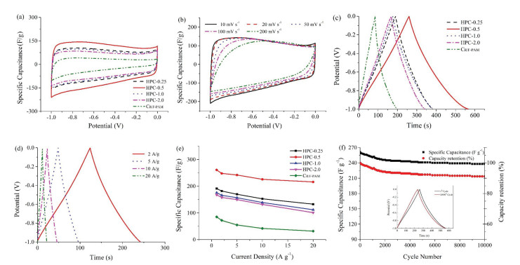
Electrochemical properties of HPCs were evaluated by employing a three-electrode configuration using 6 mol/L KOH electrolyte. In the Nyquist plots of HPCs and CR/F-PAM electrodes (Fig. S4 in Supporting information), all the HPCs electrodes present a semicircle followed by a nearly vertical line in the low frequency region, indicating an ideal capacitive behavior of the samples except CR/F-PAM [37]. All the HPCs electrodes own a low internal resistance (Ri) and charge transfer resistance (Rct) of 0.31 -0.70 V and 0.30 - 0.38Ω (Table S1 in Supporting information), demonstrating a satisfactory conductivity and fast charge propagation in aqueous electrolytes [38, 39]. The cyclic voltammetry (CV) profile of HPC-0.5 gives the highest surrounded area and namely the highest capacitance among the samples at 10 mV/s (Fig. 4a), and maintains quasi-rectangular-shaped even at 200 mV/s (Fig. 4b), manifesting rapid electrolyte movement within the HPC-0.5 electrode [11]. Gravimetric charge/discharge (GCD) curves of HPCs at 1.0 A/g (Fig. 4c) are slightly distorted from linear shapes due to the pseudocapacitive performance of oxygen functional groups. The calculated capacitances of electrodes from the charge curves are sorted in descending order: HPC-0.5 (261 F/g) > HPC-0.25 (191 F/g) > HPC-1 (177 F/g) > HPC-2 (167 F/g) > CR/F-PAM (85 F/g). The capacitance of HPC-0.5 electrode still retains 216 F/g even at 20 A/g (Fig. 4d), which outperforms those of other HPCs and CR/F-PAM (Fig. 4e). Based on the equation Cv=ρCg (ρ is the packing density of HPC-0.5, 0.40 g/cm3) [40, 41], HPC-0.5 electrode owns a corresponding volumetric capacitance of 104 and 86 F/cm3 at 1.0 and 20 A/g, respectively. Importantly, HPC-0.5 owns a high specific capacitance of 237 F/g by maintaining the capacitance retention of 90.8% after 10000 consecutive cycles under 1.0 A/g (Fig. 4f).

|
Download:
|
| Fig. 4. CV curves of HPCs and CR/F-PAM electrodes at 10 mV/s (a) and HPC-0.5 electrode at various scan rates (b) in 6 mol/L KOH electrolyte. GCD curves of HPCs and CR/F-PAM electrodes at 1.0 A/g (c) and HPC-0.5 electrode at different current densities (d) in 6 mol/L KOH electrolyte. The relationship between the specific capacitances of carbon electrodes and current densities (e). Cycling stability of HPC-0.5 electrode at 1 A/g over 10000 cycles in 6 mol/L KOH electrolyte (f). | |
The superior electrochemical performance of HPC-0.5 outperforms those of other reported carbon-based materials (Table S2 in Supporting information), which is attributed to the multiple synergistic effects of the unique hierarchical porous nanoarchitecture to ensure a continuous electron pathway and rapid ion transport. First, high surface area offers a favorable electrolyteaccessible platform for the formation of electric double layers [11, 42]. Second, abundant micropores could provide adequate active sites to accommodate charge and thus result in a large capacitance [43, 44]; Moreover, ultramicropores (< 0.7 nm) are reported to offer electrochemically available sites for aqueous electrolyte ions and thus contribute to an improved capacitance [45]. Third, mesopores offer easy ion-transmission channels which facilitate the penetration and transportation of electrolyte [46]. Fourth, macropores can serve as ion buffering reservoirs and shorten the transportation routes between electrolyte ions and electrodes surface [47]. Thus, plenty of electrolyte ions can be effectively transported from macropores to mesopores and then diffuse along the mesopore channels to the fine micropores, endowing excellent electrochemical performance of R/F-PAM IPNs- derived HPCs electrode.
In conclusion, we develop a novel and effective strategy to fabricate HPCs via in-situ activation of R/F-PAM IPNs which are prepared of simultaneous polymerization of the monomers for two polymeric networks. Using R/F network in IPNs as carbon source coupled with PAM and KOH as porogen, as-prepared HPCs possess a unique hierarchically micro-, meso- and macroporous nanoarchitecture and a large surface area of 2544 m2/g. The interconnected hierarchical porosity provides a continuous electron pathway to guarantee fast ion transportation and diffusion. Consequently, the capacitance of the HPC-0.5 electrode is 261 F/g at 1.0 A/g in aqueous electrolyte solution and maintains 216 F/g even at 20 A/g. Besides, HPC-0.5 also has long cycling life that retains the capacitance retention of 90.8% after 10000 cycles under 1.0 A/g. Thanks to the introduction of IPNs and in-situ activation, we believe that the results reported in this work may open an exciting venue for fabricating well-designed HPCs with controlled architectures as powerful candidates for advanced energy storage.
AcknowledgmentsThis work was financially supported by the National Natural Science Foundation of China (Nos. 51772216, 21703161 and 21875165), the Science and Technology Commission of Shanghai Municipality, China (No. 14DZ2261100), and the Fundamental Research Funds for the Central Universities.
Appendix A. Supplementary dataSupplementary material related to this article can befound, in the online version, at doi:https://doi.org/10.1016/j.cclet.2019.03.010.
| [1] |
D. Dubal, O. Ayyad, V. Ruiz, et al., Chem. Soc. Rev. 44 (2015) 1777-1790. DOI:10.1039/C4CS00266K |
| [2] |
C. Han, Z. Tian, H. Dou, et al., Chin. Chem. Lett. 29 (2018) 606-611. DOI:10.1016/j.cclet.2018.01.017 |
| [3] |
Q. Meng, W. Zhang, M. Hu, et al., Chem. Commun. 52 (2016) 1957-1960. DOI:10.1039/C5CC08754F |
| [4] |
Y. Fu, Q. Wei, G. Zhang, et al., Adv. Energy Mater. 8 (2018) 1801445. |
| [5] |
R. Kötz, M. Carlen, Electrochim. Acta 45 (2000) 2483-2498. DOI:10.1016/S0013-4686(00)00354-6 |
| [6] |
J.R. Miller, P. Simon, Science 321 (2008) 651-652. DOI:10.1126/science.1158736 |
| [7] |
G. Gao, Dalton Trans. 44 (2015) 18737-18742. DOI:10.1039/C5DT03696H |
| [8] |
H. Zhang, O. Noonan, X. Huang, et al., ACS Nano 10 (2016) 4579-4586. DOI:10.1021/acsnano.6b00723 |
| [9] |
Z. Song, D. Zhu, L. Li, et al., J. Mater. Chem. A 7 (2019) 1177-1186. DOI:10.1039/C8TA10158B |
| [10] |
X. Lin, H. Lou, W. Lu, et al., Chin. Chem. Lett. 29 (2018) 633-636. DOI:10.1016/j.cclet.2017.11.024 |
| [11] |
X. Wu, L. Jiang, C. Long, et al., Nano Energy 13 (2015) 527-536. DOI:10.1016/j.nanoen.2015.03.013 |
| [12] |
H. Shi, Electrochim. Acta 41 (1996) 1633-1639. DOI:10.1016/0013-4686(95)00416-5 |
| [13] |
J. Zhou, Z. Li, W. Xing, et al., Adv. Funct. Mater. 26 (2016) 7955-7964. |
| [14] |
Q. Long, W. Chen, H. Xu, et al., Energ. Environ. Sci. 6 (2013) 2497-2504. DOI:10.1039/c3ee41638k |
| [15] |
D. Zhu, Y. Wang, W. Lu, et al., Carbon 111 (2018) 667-674. |
| [16] |
J. Liu, N.P. Wickramaratne, S.Z. Qiao, et al., Nat. Mater. 14 (2015) 763-774. DOI:10.1038/nmat4317 |
| [17] |
C. Lian, C. Zhan, D.E. Jiang, et al., J. Phys. Chem. C 121 (2017) 14010-14018. DOI:10.1021/acs.jpcc.7b02827 |
| [18] |
Z. Song, L. Li, D. Zhu, et al., J. Mater. Chem. A 7 (2019) 816-826. DOI:10.1039/C8TA10406A |
| [19] |
W. Zhang, S. Bu, Q. Yuan, et al., J. Mater. Chem. A 7 (2019) 647-656. DOI:10.1039/C8TA09817D |
| [20] |
J. Yan, Q. Wang, C. Lin, et al., Adv. Energy Mater. 4 (2014) 1400500. DOI:10.1002/aenm.201400500 |
| [21] |
P. Hao, Z. Zhao, Y. Leng, et al., Nano Energy 15 (2015) 9-23. DOI:10.1016/j.nanoen.2015.02.035 |
| [22] |
P. Strubel, S. Thieme, T. Biemelt, et al., Adv. Funct. Mater. 25 (2015) 287-297. |
| [23] |
Z. Song, D. Zhu, D. Xue, et al., ACS Appl. Energy Mater. 1 (2018) 4293-4303. DOI:10.1021/acsaem.8b00928 |
| [24] |
Y.N. Sun, Z.Y. Sui, X. Li, et al., ACS Appl. Nano Mater. 1 (2018) 609-616. DOI:10.1021/acsanm.7b00089 |
| [25] |
Y. Zhang, L. Lu, Z. Zhang, et al., Chin. Chem. Lett. 29 (2018) 641-644. DOI:10.1016/j.cclet.2017.10.030 |
| [26] |
J.G. Wang, D. Jin, R. Zhou, et al., ACS Nano 10 (2016) 1936-0851. |
| [27] |
J. Ozaki, N. Endo, W. Ohizumi, et al., Carbon 35 (1997) 1031-1033. DOI:10.1016/S0008-6223(97)89878-8 |
| [28] |
J. Zhang, X. Zhong, H. Chen, et al., Electrochim. Acta 148 (2014) 203-210. DOI:10.1016/j.electacta.2014.10.023 |
| [29] |
Z. Li, E. Liu, Y. Zhu, et al., Mater. Res. Bull. 64 (2015) 6-11. DOI:10.1016/j.materresbull.2014.12.002 |
| [30] |
S.S. Wong, T.T. Teng, A.L. Ahmad, et al., J. Hazard. Mater. 135 (2006) 378-388. DOI:10.1016/j.jhazmat.2005.11.076 |
| [31] |
Y. Kitahara, K. Okuyama, K. Ozawa, et al., J. Therm. Anal. Calorim. 110 (2012) 423-429. DOI:10.1007/s10973-012-2544-7 |
| [32] |
K.S.W. Sing, D.H. Everett, R.A.W. Haul, PureAppl.Chem. 57 (1985) 603-619. DOI:10.1351/pac198557040603 |
| [33] |
L. Yu, C. Falco, J. Weber, et al., Langmuir 28 (2012) 12373-12783. DOI:10.1021/la3024277 |
| [34] |
D. Zhu, J. Jiang, D. Sun, et al., J. Mater. Chem. A 6 (2018) 12334-12343. DOI:10.1039/C8TA02341G |
| [35] |
T. Jawhari, A. Roid, J. Casado, Carbon 33 (1995) 1561-1565. DOI:10.1016/0008-6223(95)00117-V |
| [36] |
Z. Tan, G. Chen, Y. Zhu, Science 332 (2011) 1537-1541. DOI:10.1126/science.1200770 |
| [37] |
A. Jain, C. Xu, S. Jayaraman, et al., Microporous Mesoporous Mater. 218 (2015) 55-61. DOI:10.1016/j.micromeso.2015.06.041 |
| [38] |
C. Lei, N. Amini, F. Markoulidis, et al., J. Mater. Chem. A 1 (2013) 6037-6042. DOI:10.1039/c3ta01638b |
| [39] |
J. Jiang, P. Nie, S. Fang, et al., Chin. Chem. Lett. 29 (2018) 624-628. DOI:10.1016/j.cclet.2018.01.029 |
| [40] |
Y. Gogotsi, P. Simon, Science 334 (2011) 917-918. DOI:10.1126/science.1213003 |
| [41] |
Q. Wang, J. Yan, Z. Fan, Energ. Environ. Sci. 9 (2016) 729-762. DOI:10.1039/C5EE03109E |
| [42] |
Z. Jing, Y. Li, F. Huang, et al., J. Electroanal. Chem. 823 (2018) 474-481. DOI:10.1016/j.jelechem.2018.06.042 |
| [43] |
J. Zhu, X. Dan, W. Qian, et al., Small 12 (2016) 1935-1944. DOI:10.1002/smll.201600010 |
| [44] |
Zhao Jing, Gong, et al., Acta Chim. Sinica 76 (2018) 107-112. DOI:10.6023/A17090422 |
| [45] |
C. Lian, D.-e. Jiang, H. Liu, et al., J. Phys. Chem. C 120 (2016) 8704-8710. DOI:10.1021/acs.jpcc.6b00964 |
| [46] |
D. Xue, D. Zhu, M. Liu, et al., ACS Appl. Nano Mater. 1 (2018) 4998-5007. DOI:10.1021/acsanm.8b01125 |
| [47] |
X. Zheng, W. Lv, Y. Tao, et al., Chem. Mater. 26 (2014) 6896-6903. DOI:10.1021/cm503845q |