 2019, Vol. 30


Supercapacitors have emerged as an important electrical energy storage technology which will play a critical role in the large-scale deployment of intermittent renewable energy sources, smart power grids, and electrical vehicles [1, 2]. The electrode material is one of key factors to influence the performance of supercapacitors [3, 4]. Among different types of electrode materials including various carbon materials, transitional metal oxides and conducting polymers, porous carbon with nanoarchitecture are considered as the most promising materials for supercapacitors [5-8]. Especially, hollow carbon spheres (HCS) are potential electrode materials for supercapacitors owing to the short diffusion length for reactants to access the active sites in the thin shells [9]. In addition, the large cavity of HCS leaves immense room for further control of their architectures and functionalities on the optimization of their electrochemical performance [10].
To boost the electrochemical performance of HCS, porous structure should be improved for better mass loading and electrolyte transport [11]. Generally, the existence of micropores will provide great contribution to improve the specific surface area (such as porous activated carbons with large specific surface areas of more than 2000 m2/g) and abundant cumulative space for electrons. Thus, large amounts of micropores generally deliver capacitances of over 200 and 100 F/g in aqueous and organic electrolytes in supercapacitor respectively [12, 13]. However, specific capacitance is not always linearly increased with the increasing of specific surface areas because of the bad transmission capacity of micropores [14] or closed pore [15]. Carbon materials with mesopores and connected channels have been proved to overcome the drawback of conventional microporous carbon materials and exhibit a much better electrochemical performance, since the ordered mesoporous channels and their interconnections can shorten the diffusion distance of ions and reduce the diffusion resistance so that ions can easily penetrate into the inner micropores [16, 17]. Therefore, the combination of mesopores and micropores might effectively improve the electrochemical performance.
The template or sol-gel based methods have been widely accepted as common strategies to synthesize hollow carbon spheres. Whereas, the resultant HCS generally only exhibit microporous structure [10]. Hard template method is one of effective approaches to create mesopores, which highlight a nanocasting procedure by depositing a suitable carbon precursor, mostly polymers, onto the removable seeds. However, the hard template method normally suffer from tedious operating procedures and a low yield, limiting their potential for extensive uses [12]. In addition, only micropores or merely mesopores can be obtained by those methods [18], which limits the performance of HCS in electrochemical field. The combination of mesopores and micropores would effectively improve the electrochemical activity because that the mesopores are favorable for mass transport and micropores can enhance the interface contact, which is especially important for electrolyte-based applications. Therefore, the preparation of hollow carbon spheres with hierarchical porous structure is of great significance to improve their electrochemical performance. Except for the proper porous structures, the heteroatom functionalities also affected the electrochemistry properties [9]. Concretely, nitrogen functional groups have been found to improve the electrochemical stability, electrical conductivity, the wettability and pseudocapacitance of carbon materials [19-22].
Herein, we report a "dissolution-reassembly" strategy to prepare N-doped hollow mesoporous/microporous carbon spheres (H(Micro/Meso)CS) as shown in Fig. 1a. Polymerization of 3-aminophenol/formaldehyde (3-AF) resin in alkaline aqueous solution given compositionally inhomogeneous nanospheres. Based on different polymerization degree, 3-AF nanospheres are inhomogeneous with lower molecuar weight 3-AF oligomer inside, which is dissolved in acetone to form cavity in the 3-AF nanosphere. The dispersive 3-AF oligomer in solution would reassemble with tetraethyl orthosilicate (TEOS) on the shell of hollow 3-AF nanoparticles with cetyltrimethyl-ammonium bromide (CTAB) as surfactant. In a typical synthesis of H(Micro/Meso) CS, 3-aminophenol (3-AP) (0.1 g), formaldehyde solution (37 wt%, 0.1 mL), and ammonia aqueous solution (25 wt%) as catalyst were added into 30 mL deionized water and reacted at room temperature. After the reaction continued for 30 min, a certain amount of acetone (x mL) was added to selectively remove the interior part of the forming solid inhomogeneous nanospheres and stirred for another 30 min. 10 mL of CTAB surfactant aqueous solution (0.38 g) was added into the above solution under vigorous stirring. After stirring for 10 min, 0.2 mL of TEOS was added to the reaction mixture and subsequently stirred at ambient temperature overnight. After that, the solid product were collected and purified with distilled water by centrifugation. After carbonized at 800 ℃ for 3 h under an N2 atmosphere, the H(Micro/Meso)CS-x were obtained. H(Micro/Meso)CS-15, H(Micro/Meso)CS-20 and H(Micro/Meso)CS-30 were the adding amount of acetone with 15, 20 and 30 mL respectively.

|
Download:
|
| Fig. 1. Scheme of the synthesis route for H(Micro/Meso)CS (a), TEM images of H(Micro)CS, H(Micro/Meso)CS with treatment by different amount of acetone (0 mL (b–d), 15 mL (e–g), 20 mL (h–j), 30 mL (k–m)) and H(Meso)CS (n–p). | |
For comparison, hollow carbon sphere with majorly micropore was also prepared by dissolution of 3-AF sphere as previous work [10]. The method was the same with the H(Micro/Meso)CS with 20 mL acetone except the process of reassembly. Moreover, in order to investigate the effect of structure of pores, hollow mesoporous carbon spheres (H(Meso)CS) were prepared by using 3-AF as carbon sources, TEOS as the structure-assistant agent, CTAB as surfactant, and ammonia as catalyst in an ethanol-water mixed solvent as our previous work [23].
The special dissolving capacity of inhomogeneous 3-AF in acetone led us to assess the amount of acetone in forming the mesoporous shell. With increasing amount of acetone up to 20 mL in the reaction system, more 3-AF oligomer would be dissolved, resulting in higher degree of co-assembly of 3-AF oligomer and TEOS to produce H(Micro/Meso)CS-20. Fig. 1h exhibited the TEM images H(Micro/Meso)CS-20. The shell was thicker than that of H (Micro/Meso)CS-15 due to the more TEOS and 3-AF oligomer precursor. An enlarged TEM image of H(Micro/Meso)CS-20 (Fig. 1i) showed the size of inner microporous shell was 20 nm, which was thinner than that of H(Micro/Meso)CS-15 (30 nm), indicating more 3-AF was dissolved by acetone. However, the out mesoporous shell was increased from 26 nm to 35 nm for H(Micro/Meso)CS-15 and H (Micro/Meso)CS-20, suggesting successful assembly of more TEOS and 3-AF oligomer. The specific porous structure of H(Micro/Meso) CS-20 was shown in a high-resolution TEM (Fig. 1j). The mesopores in the shell were developed with a uniform size of 4 nm and are generally ordered although some twisted disordered regions were occasionally observed. In addition, compared with the H(Micro)CS, H(Micro/Meso)CS-20 showed the same cavity size but obvious core-shell structure with microporous/mesoporous shell, demonstrating the successful reassembly of 3-AF oligomer.
Since the amount of acetone affects the cavity size and the pore size on the outer shell, more amount of acetone (30 mL) was added to synthesize H(Micro/Meso)CS-30 for further investigation. As shown in Fig. 1k, the irregular sphere had no obvious double shell structure (Figs. 1k and l). The higher magnification TEM (Fig. 1m) showed the specific mesoporous structure with size of 4 nm. The main cause of the result was that the excessive acetone dissolved 3-AF spheres completely.
In order to investigate the effect of pore size, H(Meso)CS were prepared by using 3-AF as carbon sources, TEOS as the structureassistant agent and CTAB as surfactant in an ethanol-water mixed solvent as our previous work [23]. TEM images (Figs. 1n–p) were tested to investigate the structure of H(Meso)CS. Different from H(Micro/Meso)CS-30, there was no obvious core-shell structure.
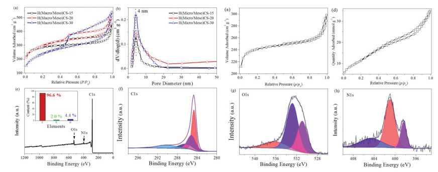
The textural properties of samples were analyzed by N2 isothermal adsorption-desorption measurements. All the samples exhibited similar type Ⅳ adsorption-desorption isotherms and type H3 hysteresis loops as depicted in Fig. 2a. The pore size distribution of H(Micro/Meso)CS samples from the adsorption branch was at ca. 4 nm in the Fig. 2b. Figs. 2c and d were the N2 isothermal adsorption-desorption measurements of H(Micro)CS and H(Meso)CS. It was obvious that a sharper increase at low relative pressure (P/P0 < 0.1) could be seen of H(Micro)CS, indicating the rich microporous structure. Nevertheless, no obvious increase at P/P0 < 0.1 could be found for the H(Meso)CS, demonstrating the homogeneous mesoporous structure of H (Meso)CS.

|
Download:
|
| Fig. 2. Nitrogen adsorption-desorption isotherms (a), pore size distribution curves (b) of H(Micro/Meso)CS, Nitrogen adsorption-desorption isotherms of H(Micro)CS (c) and H(Meso)CS (d), XPS spectra (e), C 1s (f), O 1s (g), N 1s (h) spectrum of H(Micro/Meso)CS-15. | |
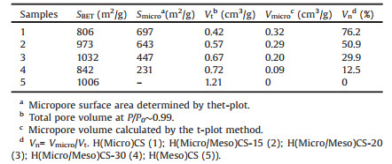
Table 1 showed the detailed textural parameters of samples. It was obvious that H(Micro/Meso)CS showed the highest surface area. The fraction of Vmicro/Vt for H(Micro/Meso)CS samples could be tuned from 50.9% to 12.5% by treating with different amount of acetone. Moreover, the H(Micro)CS possessed majorly micropores with microporous fraction of 76.2%, well agreeing with the results of TEM and N2 adsorption-desorption isotherms. At the same time, there was hardly any micropores in H(Meso)CS.
|
|
Table 1 Textural properties of H(Micro/Meso)CS, H(Micro)CS and H(Meso)CS. |
XPS was further utilized to investigate the distribution and content of nitrogen in the as-synthesized H(Micro/Meso)CS-15. As is shown in Fig. 2e, clear signals of C, N, O elements were observed from the XPS spectrum of the H(Micro/Meso)CS-15. The content of O and N species were 4.4 at% and 2.0 at% in H(Micro/Meso)CS-15 (inset of Fig. 2e). The spectrum of C 1s (Fig. 2f) could be deconvoluted into four single peaks that correspond to C=C (284.6 eV), C-C or C–N (285.8 eV), C–O (286.5 eV), and C=O/C=N (289.5 eV) functional groups. The carboxyl C=O centering at 532.5 eV, C–O at 532.5 eV, and hydroxyl oxygen in amorphous hydrogenated carbon at 536.7 eV, respectively, could be found from the oxygen functionalities revealed by deconvolution of the O 1s peaks (Fig. 2g). The N 1s spectrum (Fig. 2h) are fitted into three peaks with binding energies of 398.2, 400.1, and 404.1 eV corresponding to pyridiniC–N, pyrroliC–N, and oxidized-N, respectively.
The mesoporous/microporous shells and N-doping endowed H (Micro/Meso)CS with good performance in respect of ion transportation and hydrophily. An electrochemical workstation (CHI 760E, Chenhua Instruments, China) was used to carried out electrochemical measurements with 6 mol/L KOH solution as the electrolyte. The viscous slurry with 4~5 mg active material was coated onto Ni foam current collector (1×1 cm) as working electrode. In three-electrode system, the counter and reference electrode was Pt wire and Ag/AgCl respectively. The specific gravimetric capacitance according to the galvanostatic chargedischarge measurements: C = I∆t/∆Vm, where I(A), ∆t (s), ∆V(V) and m (g) are galvanostatic charge-discharge (GCD) current, discharge time, voltage window, and mass of active material, respectively. In the two-electrode system, the specific capacitances (C, F/g), energy density (E, Wh/kg) and power density (P, W/kg) were calculated by the following equations: C = 4I∆t/∆Vm, E = 0.5 C (∆V)2 and P = E/∆t.
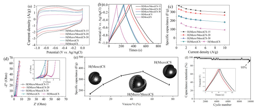
The cyclic voltammetry (CV) curves at 5 mV/s scan rate show that all of the samples presented a nearly rectangular shape as illustrated in Fig. 3a, indicating a favourable (electronic double layer capacitor) EDLC behaviour. As estimated, three H(Micro/ Meso)CS samples showed the higher specific capacity than that of H(Micro)CS and H(Meso)CS, indicating the advantages of mesoporous/microporous structure.

|
Download:
|
| Fig. 3. (a) CV curves at 5 mV/s scan rate; (b) GCD curves at 1 A/g current density; (c) Specific capacitances at different GCD current densities; (d) Nyquist plots with fitting curves; (e) Comparison of specific capacitances at 1 A/g current density for different Vmicro/Vt; (f) Cycle stability of the electrode at 5 A/g in three-electrode system of H(Micro/ Meso)CS-15. | |
The GCD curves (Fig. 3b) furtherly confirmed the significant improved capacitances of the mesoporous/microporous structure. The specific capacities calculated by using discharge branches are 359, 322, 253, 251, and 170 F/g for H(Micro/Meso)CS-15, H(Micro/ Meso)CS-20, H(Micro/Meso)CS-30, H(Micro)CS and H(Meso)CS, respectively. Fig. 3c was the rate performance at the current density range, demonstrating that the capacitance retentions were 80%, 79%, 72%, 72% and 54% for H(Micro/Meso)CS-15, H(Micro/Meso)CS-20, H(Micro/Meso)CS-30, H(Micro)CS and H(Meso)CS, respectively, indicating that the H(Micro/Meso)CS with mesoporous/microporous structure was able to provide more transport and diffusion channels for electrolyte ions.
Furtherly, as illustrated in Fig. 3d, the electrical impedance spectroscopy measurements were conducted. The H(Micro/Meso) CS, H(Micro)CS and H(Meso)CS samples showed the almost similar impedance spectra with an arc at the high frequency region and a vertical line at the low frequency region, indicating an ideal capacitive behaviour of EDLC. Compared with the H(Meso)CS and H(Micro)CS, the H(Micro/Meso)CS showed lower resistance, suggesting the microporous/mesoporous structure would improve the performance on the supercapacitor, as shown in Fig. 3e. As displayed in Fig. 3f, 95% of initial capacity of H(Micro/Meso)CS-15 was retained after 10,000 cyclic tests. The GCD curve of the 10000st cycle shows the same shape as the first cycle (Fig. 3f inset), suggesting long term electrochemical stability and excellent capacitive property.
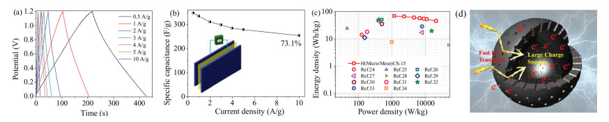
The capacitive behaviour of the H(Micro/Meso)CS-15 was further investigated in a two-electrode system in a potential range of 0–1.2 V. The quasi linear GCD curves at different current densities confirmed the good performance of H(Micro/Meso)CS-15 in EDLC (Fig. 4a). The specific capacitance of the H(Micro/Meso)CS- 15 was calculated to be 327.7 F/g at a current density of 0.2 A/g. Moreover, it could be seen that the H(Micro/Meso)CS-15 had a high capacitance retentions over 73.1% (Fig. 4b) from current density of 0.2 A/g to 10 A/g.
As illustrated in the Ragone plots of H(Micro/Meso)CS-15 (Fig. 4c), calculated by GCD in the symmetric supercapacitor. Notably, the H(Micro/Meso)CS-15 exhibited much better performance than the many of carbon spheres reported previously with higher power output capability at corresponding energy density [24-34].

|
Download:
|
| Fig. 4. (a) GCD curves of H(Micro/Meso)CS-15; (b) Specific capacitances at different GCD and model of the device of H(Micro/Meso)CS for symmetric supercapacitor (inset); (c) Ragone plots of H(Micro/Meso)CS-15; (d) Illustration of the interaction between the H(Micro/Meso)CS and ions on the electrode interface. | |
Combining material characterization and pore size, the excellent electrochemical performance attributed to the microporous/mesoporous core-shell structure, as schematically shown in Fig. 4d: large amounts of micropores provide abundant cumulative space for electrons; mesopores shorten the diffusion distance of ions and reduce the diffusion resistance so that ions can easily penetrate into the inner micropores. In addition, the nitrogen functional groups ensure a good wettability and increase the surface area for ion contact. As a result, the H(Micro/Meso)CS well balance the specific capacity and the rate performance.
In summary, a facile and effective "dissolution-reassembly" strategy has been developed to controllably fabricate hollow carbon spheres with tunable microporous/mesoporous shell. The different amounts of acetone showed discriminating ability of dissolution for 3-AF, which resulted in the change of morphology and structure in H(Micro/Meso)CS. CTAB and TEOS was added to coassemble with 3-AF oligomer to create a mesoporous out shell for H(Micro/Meso)CS. The obtained H(Micro/Meso)CS possess hollow, double-shelled microporous/mesoporous structure and high surface area. Thanks to their inherent cavity, double shell and nitrogen content, H(Micro/Meso)CS exhibited high capacitance and good performance for supercapacitors with good specific capacity (359 F/g at the current density of 1 A/g) in three-electrode and excellent high rate capability with a high capacitance retentions over 73.1% from current density of 0.2 A/g to 10 A/g in two-electrode system. This dissolution-reassembly strategy may provide a new idea for the preparation of multi-shell structure with adjustment of mesoporous and microporous structure, which can further improve the electrochemical performance of hollow carbon spheres.
AcknowledgmentsWe thank the National Natural Science Foundation of China (No. 21676070), Hebei One Hundred-Excellent Innovative Talent Program (Ⅲ) (No. SLRC2017034), Beijing National Laboratory for Molecular Sciences.
| [1] |
R.R. Salunkhe, J. Tang, Y. Kamachi, et al., ACS Nano 9 (2015) 6288-6296. DOI:10.1021/acsnano.5b01790 |
| [2] |
X. Zhang, W. Gao, X. Su, et al., Nano Energy 48 (2018) 481-488. DOI:10.1016/j.nanoen.2018.03.055 |
| [3] |
G.L. Tian, Q. Zhang, M.Q. Zhao, et al., AIChE J. 61 (2015) 747-755. |
| [4] |
P. Wu, J. He, L. Chen, et al., J. Energy Chem. 27 (2018) 1509-1515. DOI:10.1016/j.jechem.2017.09.018 |
| [5] |
S. Mezzavilla, C. Baldizzone, K.J. Mayrhofer, F. Schuth, ACS Appl. Mater. Interfaces 7 (2015) 12914-12922. DOI:10.1021/acsami.5b02580 |
| [6] |
P. Dou, Z. Cao, C. Wang, et al., Appl. Surf. Sci. 404 (2017) 342-349. DOI:10.1016/j.apsusc.2017.01.253 |
| [7] |
K.M. Horax, S. Bao, M. Wang, Y. Li, Chin. Chem. Lett. 28 (2017) 2290-2294. DOI:10.1016/j.cclet.2017.11.004 |
| [8] |
Y. Kan, G. Ning, X. Ma, Chin. Chem. Lett. 28 (2017) 2277-2280. DOI:10.1016/j.cclet.2017.11.026 |
| [9] |
Y. Li, C. Lu, S. Zhang, et al., J. Mater. Chem. A 3 (2015) 14817-14825. DOI:10.1039/C5TA02702K |
| [10] |
D.S. Bin, Z.X. Chi, Y. Li, et al., J. Am. Chem. Soc. 139 (2017) 13492-13498. DOI:10.1021/jacs.7b07027 |
| [11] |
F. Pei, T. An, J. Zang, et al., Adv. Energy Mater. 6 (2016) 1502539. DOI:10.1002/aenm.201502539 |
| [12] |
C. Long, L. Jiang, X. Wu, et al., Carbon 93 (2015) 412-420. DOI:10.1016/j.carbon.2015.05.040 |
| [13] |
L. Zhang, F. Zhang, X. Yang, et al., Small 9 (2013) 1342-1347. DOI:10.1002/smll.201202943 |
| [14] |
Y. Wang, Y. Song, Y. Xia, Chem. Soc. Rev. 45 (2016) 5925-5950. DOI:10.1039/C5CS00580A |
| [15] |
J. Niu, R. Shao, M. Liu, et al., Energy Storage Mater. 12 (2018) 145-152. DOI:10.1016/j.ensm.2017.12.012 |
| [16] |
H.J. Liu, J. Wang, C.X. Wang, Y.Y. Xia, Adv. Energy Mater. 1 (2011) 1101-1108. DOI:10.1002/aenm.201100255 |
| [17] |
Q. Zhang, K. Han, S. Li, et al., Nanoscale 10 (2018) 2427-2437. DOI:10.1039/C7NR07158B |
| [18] |
D.S. Yang, D. Bhattacharjya, S. Inamdar, et al., J. Am. Chem. Soc. 134 (2012) 16127-16130. DOI:10.1021/ja306376s |
| [19] |
M. JoséMostazo-López, R. Ruiz-Rosas, A. Castro-Muñiz, et al., Carbon 129 (2018) 510-519. DOI:10.1016/j.carbon.2017.12.050 |
| [20] |
J.S.M. Lee, M.E. Briggs, C.C. Hu, A.I. Cooper, Nano Energy 46 (2018) 277-289. DOI:10.1016/j.nanoen.2018.01.042 |
| [21] |
C. Xuan, Z. Peng, J. Wang, et al., Chin. Chem. Lett. 28 (2017) 2227-2230. DOI:10.1016/j.cclet.2017.09.009 |
| [22] |
W.K. Chee, H.N. Lim, Y. Andou, et al., J. Energy Chem. 26 (2017) 790-798. DOI:10.1016/j.jechem.2017.04.007 |
| [23] |
A. Chen, Y. Li, Y. Yu, et al., J. Alloys Compd. 688 (2016) 878-884. DOI:10.1016/j.jallcom.2016.07.163 |
| [24] |
X. Xu, Y. Liu, M. Wang, et al., Electrochim. Acta 193 (2016) 88-95. DOI:10.1016/j.electacta.2016.02.049 |
| [25] |
S. Liu, Y. Cai, X. Zhao, et al., J. Power Sources 360 (2017) 373-382. DOI:10.1016/j.jpowsour.2017.06.029 |
| [26] |
Q. Zhang, L. Li, Y. Wang, et al., Electrochim. Acta 176 (2015) 542-547. DOI:10.1016/j.electacta.2015.06.154 |
| [27] |
X. Li, L. Zhang, G. He, Carbon 99 (2016) 514-522. DOI:10.1016/j.carbon.2015.12.076 |
| [28] |
M. Liu, J. Qian, Y. Zhao, et al., J. Mater. Chem. A 3 (2015) 11517-11526. DOI:10.1039/C5TA02224J |
| [29] |
L. Mao, Y. Zhang, Y. Hu, et al., RSC Adv. 5 (2015) 9307-9313. DOI:10.1039/C4RA11028E |
| [30] |
Y.H. Dai, H. Jiang, Y.J. Hu, et al., Ind. Eng. Chem. Res. 53 (2014) 3125-3130. DOI:10.1021/ie403950t |
| [31] |
B. Chang, S. Zhang, H. Yin, B. Yang, Appl. Surf. Sci. 412 (2017) 606-615. DOI:10.1016/j.apsusc.2017.03.275 |
| [32] |
F. Sun, H. Wu, X. Liu, et al., Nano Res. 9 (2016) 3209-3221. DOI:10.1007/s12274-016-1199-2 |
| [33] |
M. Li, S. Xiang, X. Chang, C. Chang, J. Solid State Electrochem. 21 (2016) 485-494. |
| [34] |
Z. Ye, F. Wang, C. Jia, et al., Chem. Eng. J. 330 (2017) 1166-1173. DOI:10.1016/j.cej.2017.08.070 |