 2019, Vol. 30


b University of Chinese Academy of Sciences, Beijing 100049, China;
c Center of Materials Science and Optoelectronics Engineering, University of Chinese Academy of Sciences, Beijing 100049, China
Boron nitride nanotubes (BNNTs) could be imagined as a rolled up hexagonal BN layer or as a carbon nanotubes (CNTs) in which C atoms were entirely substituted by alternating B and N atoms. The B-N ionic bond in partial in h-BN, compared to the strong covalent sp2 bond exist in CNTs, might be strengthening so-called "lip–lip" interactions between adjacent layers in multi-walled BNNT and the mechanical properties of BNNT could be predicted as well as CNTs for this regard [1].
For the future application of the nanotubes in nanoscale or microscale devices, it was important to understand the failure and deformation mechanisms of these nanotubes. Until now, intensive research had been carried out, both experimentally and theoretically, on the buckling instability of CNTs in the last two decades [2-7]. However, only very few experiments had been performed to date with respect to the experimental examination of mechanical properties of BNNTs. For instance, Golberg et al. [8] performed direct bending force measurements of individual multiwalled BNNTs using an atomic force microscopy (AFM) stage installed inside the TEM (AFM-TEM) and the bending angles of BNNTs beyond 30°-40º resulted in the elastic deformation, the elastic modulus was determined as ~0.5-0.6 TPa. Similar approach was used by Ghassemi et al. [9, 10] and BNNTs survived from the lowangle test and their modulus were given as ~0.5 TPa. However, for AFM-TEM approach, the force value was calculated indirectly from the displacement values conducted by the piezo-resistive properties of the Si cantilever. It was worth noting that the noise of the present AFM-TEM system (30–40 nN) was intrinsically high and the noise level was related with the electron dose of the instrument, and the properties of a nanotube supporting substrate because of the backscattered electrons [8].
A novel TEM holder equipped with a transducer allowed to realize quantitative nanomechanical testing by measuring the force directly in real-time. In recent years, nanomechanical properties of materials, such as GaAs [11], SiC [12] nanowires, CNT [13], silica spheres [14], single crystal Ni [15], and even graphene [16] were studied using this technology. However, to our best knowledge, it was still opening in experimental to directly measure the force-time curve of BNNT under compression. With direct force measurement and in situ TEM observation, it was possible to evaluate the compression stresses and to estimate the elastic modulus of individual BNNTs while carefully surveying for possible tube lattice changes through high resolution transmission electron microscope (HRTEM) of the buckling position. In addition, the real-time video recording of the in situ deformation process allowed us to follow uninterruptedly the sequence and time scale of the BNNT buckling and post-buckling phenomena that took place due to the applied axial compression forces. In this work, the structure evolution behavior of BNNT was investigated by TEM technology while applying an in situ axial compression. Real-time video, as well as the compression force, of the whole loading process was recorded where the mechanical deformation of BNNT began, buckled and ended with fracture. Young's modulus and elasticity coefficient of BNNT were calculated by Euler formula and Hooker's law, respectively.
High-quality chemical vapor deposition (CVD) BNNTs with uniform morphology in tube diameters and number of layers were purchased from Nanjing XFNANO Materials Tech Co., Ltd., and they were dispersed into dimethylforamide (DMF) under ultrasonication at room temperature until the suspension turned to white. 3 μL of the solution was drop-casted onto the side of a push-to-pull (PTP) devicewhichwas thenfixedon theTEMholder. Finally, the X, Y, andZ positions of the diamond tip and the target BNNT were adjusted through the nanoscale precision piezo-driven inside the TEM.
The PI-95 TEM PicoIndenter instrument from Hysitron was the full-fledged depth-sensing indenter capable of direct observation nanomechanical testing inside a TEM. The test was performed using displacement control, and all the loading speed was kept constant at 2 nm/s. The sequential images with an exposure time of 0.2 s at 5 fps was recorded by the Gatan894 CCD camera. In order to avoid the radiation damage and knockout damage, the electron beam intensity during experiments is settled to ~0.5 A/cm2 both in imaging and video recording. All the experiments were performed in the 200 kV TEM.
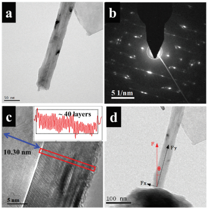
XRD characterization results shown in Fig. S1 (Supporting information) confirmed that the BNNTs are high crystallinity with a hexagonal structure (PDF #34-0421). A single BNNT demonstrated tubular structure feature and high crystalline structure under TEM (Figs. 1a and b). The thickness of the BNNT was 13.52 nm which measured to be 40 layers with 0.38 nm inter-wall spacing. The diameter of the inner tube was measured approximate 10.30 nm. The outer diameter of the BNNT was measured 37.34 nm. Fig. 1d showed the TEM image of the initial position of BNNT against diamond tip with analysis of the associated forces direction in the following in-situ compression test.

|
Download:
|
| Fig. 1. (a) TEM image of the BNNT compressed in the following experiment. (b) SAED pattern of the corresponding BNNT. (c) High resolution image of the BNNT and inset shows the histogram profile of the HRTEM. (d) TEM image of the initial position of BNNT against diamond tip with analysis of the associated forces direction. | |
Three compression cycles were loaded using the displacement control at the same speed. The diamond tip marched forward from the same start point, which could be carefully examined by the TEM image and the distance punched 50 nm, 100 nm, 150 nm, respectively. Fig. 2 showed a series of microscopy images extracted from Movie 1 (Supporting information) for a BNNT before compression, at buckling point, post-buckling and recovery process. When the diamond tip touched the BNNT at 8.6 s, the measured force rose abruptly from 0 to about 2200 nN (red curve in Fig. 2a). At the force increased to 2200 nN, i.e., Fy = 2124 nN, the BNNT started to buckle and then the force decreased sharply where indicated onset of buckling instabilities in the nanotube associated with a release of the local compressive stress (Fig. 2c). The critical buckling load was defined as the maximum load after which postbuckling deformation occurred (Fig. 2d). The BNNT was subjected to combined bending and compression under increasing displacement loading. After the diamond tip punched 32 nm at 25 s, the compression force failed to 875 nN with a bending angle of 22.6°. The diamond tip stayed for 10 s while the force slightly fell to 750 nN. The BNNT started to recover to its original form with the diamond tip retracting.

|
Download:
|
| Fig. 2. (a) The force–time curve of the whole testing process (from 5 s to 55 s). (b–g) A series of microscopy images extracted from Movie 1 (Supporting information) for a BNNT before compression (a), at buckling point (b), post-buckling (c, d), and recovery process (e–g). Points 1–6 correspond to the images (b–g), respectively. The scale bar in b–g is 50 nm. | |
In the second loading, the similar force–time curve measured and corresponding real-time images were shown in Fig. S2 (Supporting information). The bending direction turned to left and reached its maximum deformation at 50.0 s and then returned to its original form when the diamond tip was withdrawn. Compared Figs. 2b–g and Figs. S2a–i, the structure and morphology of the BNNT had not been changed before and after compression. It indicated that the bending deformation was elastic process. The maximum bending angle and force measured were 24.6° and 1812 nN. The slight decrease of maximum force compared to the first compression might be caused by the BNNT bending direction which was consistent with movement of diamond tip. In the third compression load, the BNNTs fractured. The maximum bending angle and forces measured were 51.7° and 2330 nN as shown in Fig. S3 (Supporting information). Theoretically, a bending angle of 70° could lead to failure or breaking of B—N bonds in pristine single-wall BNNTs [17]. After unloading the compression, a residual plastic buckle of 10.4° angled kink could remain in the structure of the nanotube (Fig. S3k). It was similar to the previously report that at bending angles of 115°, a 30° angled kink was formed after unloading using AFM method [8].
Figs. 3a–c demonstrated high resolution TEM (HRTEM) images taken from the bending position of BNNT (marked with arrow) after 1st, 2nd and 3rd compression, respectively. The HRTEM imaging of the nanotubes after unloading revealed no apparent fracture after first compression and only a little fracture on the BNNT surface after second load. Combined the HRTEM results with the directly measured F-T curve, it indicated that the first two buckling and post-buckling of BNNT were reversible in structure. In the 3rd compression, the HRTEM image at the bending position (marked in Fig. 3d) showed that the tubular crystal structure of BNNT was torn and broken. The destroyed lattice was perpendicular to the BNNT in the bending position. However, the original crystal structure was retained for the rest part of BNNT as shown inset of Fig. 3d.

|
Download:
|
| Fig. 3. HRTEM images taken from the bending position of BNNT (marked with arrow) after 1st, 2nd and 3rd compression, respectively. | |
The appearance of reversible V-shape buckles was measured of bending angle to 22.6° and 24.6° (Fig. 2d and Movie in Table S1 in Supporting information) and compression forces. It suggested that the buckle formation was reversible and was not affected by defects. Otherwise, the stress would concentrate on the defect location and lead to the same buckling behavior under compression. The V-shape in our case was possibly accompanied by the formation pentagon–heptagon pairs (Stone–Wales transformation) though the bond energy was unfavorable to B—B or N—N bonds. The axial compression force, which led to the bending deformation, could provide the energy required for this energetically unfavorable transition. The reversible V-shape buckles indicated that these thermodynamically unstable B—B or N—N bonds could switch back to stable B—N bonds after the compression force unloaded, due to the more energetically favorite BNNT structures. It also could be concluded from the above HRTEM analysis of the structure in BNNT bending position. Hence, the BNNT transmitted the compression force through the abovementioned mechanism to avoid mechanical failure and maintain the tubular structure. The mechanism was in agreement with the previously literature report [10, 18].
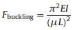
The mechanical properties of BNNT could be estimated by applying the Euler formula (Eq. (1)). In Eq. (1), Fbuckling was the buckling force (Fbuckling=Fmax cosθ, θ was the angle between diamond tip and BNNT at buckling point in Fig. 1d), E was the Young's modulus and I was the moment of inertia of the BNNTs with outer and inner diameters of d2 and d1, respectively. The effective length μL was expressed in term of an effective-length factor, where L~378.13 nm was the actual length of the BNNT. For a nanotube fixed at the top and free at the base was called a fixedfree column, where the value of μ was 2 [19]. The Young's modulus was calculated as 1.05~1.37 TPa through the directly measured critical buckling force of BNNT. The calculation results were summarized in Table S1, in which it was consistent with the values (i.e., E = 1.22 TPa) mesured by thermal vibration method [20]. Considering it was an elastic process before buckling, the elasticity coefficient ~198.7-255.9 N/m of BNNT was calculated by the Hooker's law (Eq. (3)).
|
(1) |

|
(2) |

|
(3) |
The buckling behavior as well as the structure evolution of BNNTs with axial compression were studied by TEM equipped with a force transducer holder. Young's modulus ~1.05-1.37 Tpa and elasticity coefficient ~198.7-255.9 N/m of BNNT were calculated by Euler formula and Hooker's law, respectively. The real time analysis structure evolution of BNNT with compression showed that the formation of V-shape in the post-buckling before BNNT fracture was reversible. The approach therefore could be extended to other materials with similar structure for their mechanical properties with compression.
AcknowledgmentsThis work was supported by the National Natural Science Foundation of China (Nos. 51573201, 21773205, 51501209 and 201675165), Key R&D Program of Yunnan Province (No. 2018BA068), NSFC-Zhejiang Joint Fund for the Integration of Industrialization and Informatization (No. U1709205), National Key R&D Program of China (No. 2017YFB0406000), the Project of the Chinese Academy of Sciences (Nos. YZ201640 and KFZD-SW- 409), Public Welfare Project of Zhejiang Province (No. 2016C31026), Science and Technology Major Project of Ningbo (Nos. 2016B10038 and 2016S1002), International S&T Cooperation Program of Ningbo (No. 2017D10016), and the 3315 Program of Ningbo for financial support. We also thank the financial support by the Science and Technology Major Project of Ningbo (No. 2015S1001).
Appendix A. Supplementary dataSupplementary material related to this article can be found, in the online version, at doi: https://doi.org/10.1016/j.cclet.2019.02.024.
| [1] |
X. Blase, A.D. Vita, J.C. Charlier, R. Car, Phys. Rev. Lett. 80 (1998) 1666-1669. DOI:10.1103/PhysRevLett.80.1666 |
| [2] |
X. Shi, X. He, L. Wang, L. Sun, Carbon 125 (2017) 289-298. DOI:10.1016/j.carbon.2017.09.053 |
| [3] |
M.F. Yu, O. Lourie, M.J. Dyer, et al., Science 287 (2000) 637-640. DOI:10.1126/science.287.5453.637 |
| [4] |
X. Wang, H.K. Yang, Phys. Rev. B 73 (2006) 085409. DOI:10.1103/PhysRevB.73.085409 |
| [5] |
C.M. Wang, Y.Y. Zhang, Y. Xiang, J.N. Reddy, Appl. Mech. Rev. 63 (2010) 030804. DOI:10.1115/1.4001936 |
| [6] |
J. Zhao, M.R. He, S. Dai, et al., Carbon 49 (2011) 206-213. DOI:10.1016/j.carbon.2010.09.005 |
| [7] |
C.G. Wang, Y.P. Liu, J. Al-Ghalith, et al., Carbon 102 (2016) 224-235. DOI:10.1016/j.carbon.2016.02.041 |
| [8] |
D. Golberg, P.M.F.J. Costa, O. Lourie, et al., Nano Lett. 7 (2007) 2146-2151. DOI:10.1021/nl070863r |
| [9] |
H.M. Ghassemi, C.H. Lee, Y.K. Yap, R.S. Yassar, J. Appl. Phys. 108 (2010) 024314. DOI:10.1063/1.3456083 |
| [10] |
H.M. Ghassemi, C.H. Lee, Y.K. Yap, R.S. Yassar, Nanotechnology 22 (2011) 115702. DOI:10.1088/0957-4484/22/11/115702 |
| [11] |
B. Chen, Q. Gao, Y. Wang, et al., Nano Lett. 13 (2013) 3169-3172. DOI:10.1021/nl401175t |
| [12] |
Z. Zhang, J. Cui, B. Wang, et al., Nanoscale 10 (2018) 6261-6269. DOI:10.1039/C8NR00341F |
| [13] |
R.B. Patel, T. Chou, A. Kanwal, et al., Sci. Rep. 6 (2016) 30495. DOI:10.1038/srep30495 |
| [14] |
M. Mačković, F. Niekiel, L. Wondraczek, E. Bitzek, E. Spiecker, Scr. Mater. 121 (2016) 70-74. DOI:10.1016/j.scriptamat.2016.04.019 |
| [15] |
V. Samaeeaghmiyoni, H. Idrissi, J. Groten, R. Schwaiger, D. Schryvers, Micron (2017) 66-73. |
| [16] |
Z. Liao, S.L. Medrano, T. Zhang, et al., Sci. Rep. 7 (2017) 211. DOI:10.1038/s41598-017-00227-3 |
| [17] |
A.N. Enyashin, A.L. Ivanovskii, Inorg. Mater. Appl. Res. 42 (2006) 1336-1341. DOI:10.1134/S0020168506120090 |
| [18] |
A. Loiseau, F. Willaime, N. Demoncy, G. Hug, H. Pascard, Phys. Rev. Lett. 76 (1996) 4737-4740. DOI:10.1103/PhysRevLett.76.4737 |
| [19] |
P.C. Tsai, Y.R. Jeng, Y.X. Huang, K.T. Wu, Appl. Phys. Lett. 103 (2013) 053119. DOI:10.1063/1.4817668 |
| [20] |
N.G. Chopra, A. Zettl, Solid State Commun. 105 (1998) 297-300. DOI:10.1016/S0038-1098(97)10125-9 |