 2019, Vol. 30


Magnetic materials have been playing important roles in many fields [1-4]. Besides synthesizing new materials [5-15], tuning the magnetism of existing materials has caused widespread attention [16-21]. The magnetism of materials can be tuned by many factors, such as temperature [16], pressure [17], light [18-20], guest ions [21]. Control of magnetism by electrical migration of ions is of significant importance [22-29]. Electrochemical intercalation of guest ions, which is the fundamental of rechargeable battery, has been considered as a powerful strategy in tuning the magnetism [30-38]. This route is expected to be widely applied because of the great availability of electrode materials. For example, Talham etc. reported that the magnetism of a core-shell structured material could be tailored by intercalation of lithium ions [33].
So far, most of the guest ions are monovalent cations, because most of the magnetic electrode materials cannot accommodate multivalent cations. The main reason is that the spacing of the interstitial sites in most of the materials is rather limited. Mixed valence coordination frameworks, including metal-organic frameworks, contain tunable pores ranging from 0.2 nm to 5 nm, therefore can host multi-valence cations. Recently, various coordination frameworks have been selected as electrode materials for alkali earth ions or even transition metal ions [39, 40]. Prussian blue analogues (PBA) have been usually chose. For example, Yamada et al. has successfully inserted Mg2+ into the CuFe-PBA [39]. Cui et al. used the CuFe-PBA as the host material, and successfully inserted many kinds of metal ions, including monovalent and multivalent cations [40].
In this work, we report that mixed valence metal cyanide compounds can accommodate monovalent cations, divalent cations, and trivalent cations. Through intercalation of these guest ions, the host frameworks showed ferromagnetic, superparamagnetic and paramagnetic properties.
CuFe-PBA was chosen as the host material. The structure of this coordination framework is described in Fig. S1 (Supporting information) [41, 42]. It is cubic with Fm3m space group. Each cyanide bridge has a Cu ion at the end of N, and a Fe ion at the end of C. The structure can be denoted as Cu-NC-Fe. In addition, both Cu center and Fe center has a coordination number of 6, which result in a 3-D structure. As we can see in Fig. S1, there are vacancies in the center of each sub-cell, providing spaces for guest ions. The Xray diffraction (XRD) pattern and the scanning electron microscopy (SEM) images of the prepared CuFe-PBA are shown in Fig. S2 (Supporting information). The XRD pattern (Fig. S2a) matches with the standard pattern cubic Cu3(Fe(CN)6)2 (PDF#86-0513) with a lattice parameter to be 10.05 Å. From the SEM image (Fig. S2b), we can see that the shape of the CuFe-PBA particles is close to sphere with a diameter of 40 nm approximately.
Magnetism origination of the CuFe-PBA was described in Fig. S3 (Supporting information) [31, 43, 44]. The CuⅡ at the end of N is in a weak coordination field, shwoing a high-spin state (t2g6eg3, S =1/2). TheFeⅢ atthe end of C is in a strong coordination field which makes the FeⅢ in a low-spin state (t2g5, S=1/2). This means that the CuⅡ has one unpaired electron on eg orbit and FeⅢ has one unpaired electron on t2g orbit. The eg orbit and t2g orbit are perpendicular to each other, and the interaction between them is ferromagnetic coupling. Therefore, CuFe-PBA is ferromagnetic when the temperature is lower than ferromagnetic ordering temperature (Tc= 18 K). The temperature depended magnetization (M-T) curve and field depended magnetization (M-H) curve were displayed in Fig. S4 (Supporting information), indicating that the CuFe-PBA is ferromagnetic.
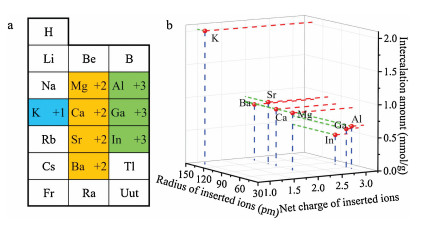
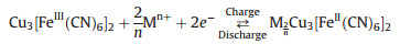
We selected monovalent ion (K+), divalent ions (Mg2+, Ca2+, Sr2+, Ba2+) and trivalent ions (Al3+, Ga3+, In3+). Their positons in periodic table of elements were marked in Fig. 1a. These guest ions were inserted by electrochemical intercalation as illustrated in Fig. S5 (Supporting information). The FeⅢ in the framework can be reduced to FeⅡ to neutralize the net charge. Fig. S6 (Supporting information) showed the cyclic voltammetry (CV) and galvanostatic discharge profiles for intercalation of K+, Ca2+, and In3+. The reduction peaks in the CV curves and the capacity in galvanostatic discharge profiles indicated insertion of these ions. The CV and galvanostatic discharge profiles for insertion of other ions were depicted in Fig. S7 (Supporting information). To summarize, the reaction process can be described by the Eq. (1),

|
Download:
|
| Fig. 1. (a) Selected guest ions used in this research (Monovalent ion: blue. Divalent ions: yellow. Trivalent ions: green). (b) Relationship among the intercalation amount, the radius, and the net charge of the ions. | |
|
(1) |
Here, M refers to the metal ions, n is the charge of the metal ions.
Fig. 1b showed the relationship among the intercalation amount, the radius, and the net charge of the ions. From this diagram, it is clear that the K+ can be intercalated mostly, because of its lowest net charge, while insertion of In3+ is difficult due to its high net charge. Among all the divalent ions (Mg2+, Ca2+, Sr2+, Ba2+), the intercalation amount decreases gradually while the ion radius rising. This phenomenon is clearer for the trivalent ions (Al3+, Ga3+, In3+). This means the insertion amount decrease when the ions charge or radius increase.
The reason behind the difference in inserting quantities is that the ions with more net charge suffer stronger repulsion force from the host frameworks. In addition, larger radius of the guest ions hinders embedding into the host frameworks. So the inserting quantity of the Ca2+ ions is more difficult than the K+ ions. Meanwhile, fewest In3+ ions could be inserted into the framework. Though both Al3+ and Ga3+ ions are trivalent, they have smaller radius than In3+ ions.
All the inserted samples were characterized by XRD (Fig. S8 in Supporting information). All the diffraction profiles were indexed as cubic with Fm-3 m space group which is almost identical to the initial host frameworks. This result indicated that the structure of the host frameworks has not been changed after insertion of the guest ions. The distribution of the inserted ions was investigated by energy dispersive x-ray spectroscopy (EDS) as shown in Fig. S9 (Supporting information). For three typical ions (K+, Ca2+, and In3+), the inserted ions were found to be dispersed well in all the host particles.
After insertion of these ions, the magnetic properties of the materials were characterized by PPMS. From the results shown in Figs. S10 and S11 (Supporting information), we found that the alternated magnetism could be categorized into three types: paramagnetic, superparamagnetic, and ferromagnetic. When the inserted ion was K+, the frameworks became paramagnetic (Fig. S10a). Fig. S10b1 is the M-T curve of the sample after insertion of Ca2+. A slight rise of the magnetization was observed at the low temperature region (< 18 K), indicating the magnetism of the material might become ferromagnetic. However, in the M-H curve (Fig. S10b2), the curve was not straight and hardly had any coercivity, indicating superparamagnetism. After insertion of In3+ ions, the magnetism remained to be ferromagnetic which was similar to the intrinsic host frameworks, although the magnetization was lower as shown in Fig. S10c. The M-T and M-H curves of the samples inserted with other ions (Mg2+, Sr2+, Ba2+, Al3+, and Ga3+ ions) were displayed in Fig. S11. All the samples were superparamagnetic, similar to the behavior of the samples inserted with Ca2+ ions. We should note that the magnetism change of the sample does not come from the impurities during guest ion insertion. We have compared the M-T curve of samples collecting with iron spoon and ox horn spoon in Fig. S12 (Supporting information). We can see that the magnetic properties of the sample collecting with the ox horn spoon has no been alternated. However, the sample harvested by the iron spoon become ferromagnetic.
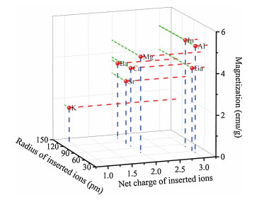
The magnetization of all the samples was summarized in Fig. 2. When the net charges of the cations became higher, the magnetization was increased. The larger the radius of the guest ions, the higher the magnetization of the obtained samples. Because less cations could be inserted into the host frameworks when the intercalated cations had more net charges or larger ionic radius, less Fe3+ nodes in the frameworks were reduced. As a result, the magnetization of the obtained samples was high.

|
Download:
|
| Fig. 2. The relationship among the magnetization, the radius, and the net charge of the ions. | |
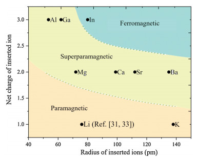
We also summarized the magnetism phase diagram of all the samples after insertion of the guest ions (Fig. 3). Insertion of the In3+ ions resulted in ferromagnetism (blue region).In contrast, embedding of the K+ ions ledto paramagnetism (pink region). Forcomparison, we also summarized the magnetism of the PBAs after insertion of Li+ ions by referring previousreports [31, 33]. Similarly, the PBAswere changed from ferromagnetic and paramagnetic after intercalation of monovalent Li+ ions. For all the other intercalated ions, the samples became superparamagnetic (yellow region).

|
Download:
|
| Fig. 3. The magnetic phase diagram of the framework after the insertion of guest ions with different radius and net charges. | |
X-ray photoelectron spectroscopy (XPS) was used to help understanding the magnetism change. The samples after insertion of K+, Ca2+ and In3+ were characterized (Fig. S13 in Supporting information). When K+ ions were inserted, no FeⅢ was detected. The frameworks only contain CuⅡ (S = 1/2) and FeⅡ (S = 0). As a result, only one paramagnetic center exists, leading to zero exchange couple. After insertion of Ca2+ and In3+ ions, partial FeⅢ nodes were left. The peaks at 709 eV and 722 eV were ascribed to be FeⅡ, whilethe peaksat 710.6 eV and 724.2 eV belonged to FeⅢ [45, 46]. That means that CuⅡ (S = 1/2), FeⅢ (S = 1/2), and FeⅡ (S = 0) all exist in the samples. In these cases, the samples contained both the ferromagnetic and paramagnetic regions. Because ferromagnetism is stronger than paramagnetism, so the samples after insertion of In3+ became ferromagnetic. As for the superparamagnetic samples, we deducted that their ferromagnetic regions were smaller than critical size of the ferromagnetic domain. Because there were less FeⅢ in the frameworks intercalated with Ca2+ than which with In3+, the unreduced parts were smaller in the frameworks loading with the Ca2+ ions. The small size of the ferromagnetic regions could not resist thermal disturbance, showing superparamagnetism.
Fig. S14 (Supporting information) summarized our interpretation. After intercalation with the guest ions, the origin FeⅢ (orange) in the initial host frameworks were reduced to FeⅡ (green) when guest ions were inserted. When all the FeⅢ were reduced to FeⅡ, the frameworks became paramagnetic. When partial FeⅢ were reduced, if the size of the region contained FeⅢ was smaller than the critical size, the frameworks were superparamagnetic; if the size of the region contained FeⅢ was larger than the critical size, the frameworks exhibited ferromagnetism.
In summary, we have demonstrated that the CuFe-PBA can accommodate monovalent, divalent, and trivalent cations. The magnetism of the host material CuFe-PBA was tuned from paramagnetic to superparamagnetic and finally ferromagnetic. We should emphasize that superparamagnetism obtained by ions intercalation has not been reported before (Table S1 in Supporting information). The reason was that the amount of the inserted cations was different due to the net charge and radius of these ions. The reduction degree of the FeⅢ was related to the insertion amount of the guest ions, and eventually affected the magnetism of the frameworks. Incorporation of the guest ions is believed to be a promising method in tuning other solid-state property of solids.
AcknowledgmentThis work was supported by the National Natural Science Foundation of China (Nos. 21473059, U1830130, 61504043, 61774061).
Appendix A. Supplementary dataSupplementary data associated with this article can be found, in the online version, at https://doi.org/10.1016/j.cclet.2019.03.007.
| [1] |
B.V. Harbuzaru, A. Corma, F. Rey, et al., Angew. Chem. Int. Ed. 47 (2008) 1080-1083. |
| [2] |
H.J. Richter, A. Lyberatos, U. Nowak, R.F.L. Evans, R.W. Chantrell, J. Appl. Phys. 111 (2012) 033909. DOI:10.1063/1.3681297 |
| [3] |
S. Jadoon, A. Waseem, M. Yaqoob, A. Nabi, Chin. Chem. Lett. 21 (2010) 712-715. DOI:10.1016/j.cclet.2009.11.013 |
| [4] |
H. Zhang, F. Huang, D.L. Liu, P. Shi, Chin. Chem. Lett. 26 (2015) 1137-1143. DOI:10.1016/j.cclet.2015.05.026 |
| [5] |
P.A. Sundaram, R. Augustine, M. Kannan, Biotechnol. Bioprocess Eng. 17 (2012) 835-840. DOI:10.1007/s12257-011-0582-9 |
| [6] |
S. Wu, A.Z. Sun, F. Zhai, A.A. Volinsky, et al., Mater. Lett. 65 (2011) 1882-1884. DOI:10.1016/j.matlet.2011.03.065 |
| [7] |
M. Hu, J.S. Jiang, F.X. Bu, et al., RSC Adv. 2 (2012) 4782-4786. DOI:10.1039/c2ra01190e |
| [8] |
M. Darbandi, F. Stromberg, J. Landers, et al., J. Phys. D Appl. Phys. 45 (2012) 195001. DOI:10.1088/0022-3727/45/19/195001 |
| [9] |
O.M. Lemine, K. Omri, B. Zhang, et al., Uperlattices Microstruct. 52 (2012) 793-799. DOI:10.1016/j.spmi.2012.07.009 |
| [10] |
G.H. Gao, R.R. Shi, W.Q. Qin, et al., J. Mater. Sci. 45 (2010) 3483-3489. DOI:10.1007/s10853-010-4378-7 |
| [11] |
H. Xu, B.W. Zeiger, K.S. Suslick, Chem. Soc. Rev. 42 (2013) 2555-2567. DOI:10.1039/C2CS35282F |
| [12] |
L. Wu, H. Yao, B. Hu, S.H. Yu, Chem. Mater. 23 (2011) 3946-3952. DOI:10.1021/cm2013736 |
| [13] |
D.P. Dong, J.Q. Xiao, P.F. Zhuang, et al., Inorg. Chem. Commun. 21 (2012) 84-87. DOI:10.1016/j.inoche.2012.04.019 |
| [14] |
D.P. Dong, H. Zheng, L. Zhao, et al., Sci. China Chem. 55 (2012) 1018-1021. DOI:10.1007/s11426-012-4597-7 |
| [15] |
R.M. Wen, S.D. Han, H. Wang, Y.H. Zhang, Chin. Chem. Lett. 25 (2014) 854-858. DOI:10.1016/j.cclet.2014.05.026 |
| [16] |
S. Ohkoshi, T. Matsuda, H. Tokoro, K. Hashimoto, Chem. Mater. 17 (2005) 81-84. DOI:10.1021/cm048461x |
| [17] |
C. Eugenio, G.L.M. Carmen, K. Tomasz, et al., J. Am. Chem. Soc. 130 (2008) 15519. DOI:10.1021/ja8047046 |
| [18] |
K. Noriyuki, H. Masanori, K. Izuru, et al., J. Am. Chem. Soc. 131 (2009) 212. DOI:10.1021/ja806879a |
| [19] |
M. Nishino, K. Boukheddaden, S. Miyashita, F. Varret, Phys. Rev. B 72 (2005) 73-80. |
| [20] |
T. Liu, H. Zheng, S. Kang, et al., Nat. Commun. 4 (2013) 3826. |
| [21] |
B. Li, R.J. Wei, J. Tao, et al., J. Am. Chem. Soc. 132 (2010) 1558-1566. DOI:10.1021/ja909695f |
| [22] |
Q.Y. Zhang, X. Luo, L.N. Wang, et al., Nano Lett. 16 (2016) 583. DOI:10.1021/acs.nanolett.5b04276 |
| [23] |
Y.N. Yan, X.J. Zhou, F. Li, et al., Appl. Phys. Lett. 107 (2015) 122407. DOI:10.1063/1.4931752 |
| [24] |
X.J. Zhou, Y.N. Yan, M. Jiang, et al., J. Phys. Chem. C 120 (2016) 1633-1639. DOI:10.1021/acs.jpcc.5b10794 |
| [25] |
D.A. Gilbert, J. Olamit, R.K. Dumas, et al., Nat. Commun. 7 (2016) 11050. DOI:10.1038/ncomms11050 |
| [26] |
M. Okubo, K. Kagesawa, Y. Mizuno, et al., Inorg. Chem. 52 (2013) 3772-3779. DOI:10.1021/ic302364d |
| [27] |
K. Taniguchi, K. Narushima, J. Mahin, W. Kosaka, H. Miyasaka, Angew. Chem. Int. Ed. 55 (2016) 5238-5242. DOI:10.1002/anie.201601672 |
| [28] |
T. Tsuchiya, K. Terabe, M. Ochi, et al., ACS Nano 10 (2016) 1655-1661. DOI:10.1021/acsnano.5b07374 |
| [29] |
T. Yamada, K. Morita, K. Kume, H. Yoshikawa, K. Awaga, J. Mater. Chem. C 2 (2014) 5183-5188. DOI:10.1039/C4TC00299G |
| [30] |
K. Taniguchi, K. Narushima, H. Sagayama, et al., Adv. Funct. Mater. 27 (2017) 1604990. DOI:10.1002/adfm.201604990 |
| [31] |
M. Okubo, D. Asakura, Y. Mizuno, et al., Angew. Chem. Int. Ed. 50 (2011) 6269-6273. DOI:10.1002/anie.201102048 |
| [32] |
Y. Mizuno, M. Okubo, K. Kagesawa, et al., Inorg. Chem. 51 (2012) 10311-10316. DOI:10.1021/ic301361h |
| [33] |
C.H. Li, M.K. Peprah, D. Asakura, et al., Chem. Mater. 27 (2015) 1524-1530. DOI:10.1021/cm503639a |
| [34] |
W. Antje, K. Heike, P.P. Irena, et al., Inorg. Chem. 41 (2002) 5706-5715. DOI:10.1021/ic0201654 |
| [35] |
F.Q. Li, W. Zhang, A. Carné-Sánchez, et al., Inorg. Chem. 57 (2018) 8701-8704. DOI:10.1021/acs.inorgchem.8b00959 |
| [36] |
W. Zhang, Y.Y. Zhao, V. Malgras, et al., Angew. Chem. Int. Ed. 55 (2016) 8228-8234. DOI:10.1002/anie.201600661 |
| [37] |
Y.J. Fang, C.X. Chen, X.P. Ai, H.X. Yang, Y.L. Cao, Acta Phys-Chim. Sin. 33 (2017) 211-241. |
| [38] |
S. Liu, L.Y. Shao, X.J. Zhang, Z.L. Tao, J. Chen, Acta Phys.-Chim. Sin. 34 (2018) 581-597. |
| [39] |
Y. Mizuno, M. Okubo, E. Hosono, et al., J. Mater. Chem. A 1 (2013) 13055-13059. DOI:10.1039/c3ta13205f |
| [40] |
R.Y. Wang, B. Shyam, K.H. Stone, et al., Adv. Energy Mater. 5 (2015) 1401869. DOI:10.1002/aenm.201401869 |
| [41] |
C.D. Wessells, R.A. Huggins, Y. Cui, Nat. Commun. 2 (2011) 550. DOI:10.1038/ncomms1563 |
| [42] |
E. Reguera, J. Rodríguez-Hernández, A. Champi, et al., Z. Phys. Chem. 220 (2006) 1609-1619. DOI:10.1524/zpch.2006.220.12.1609 |
| [43] |
D. Asakura, Y. Nanba, M. Okubo, et al., J. Phys. Chem. Lett. 5 (2014) 4008-4013. DOI:10.1021/jz501738m |
| [44] |
M. Verdaguer, G.S. Girolami, Magnetic prussian blue analogs, in: J.S. Miller, M. Dorillon (Eds.), Magnetism: Molecules to Materials V, Wiley-VCH, New York, 2005, pp. 283-346.
|
| [45] |
T. Yamashita, P. Hayes, Appl. Surf. Sci. 254 (2008) 2441-2449. DOI:10.1016/j.apsusc.2007.09.063 |
| [46] |
A. Lisowska-Oleksiak, M. Wilamowska, V. Jasulaitiené, Electrochim. Acta 56 (2011) 3626-3632. DOI:10.1016/j.electacta.2010.12.092 |