 2019, Vol. 30


b School of Chemistry and Chemical Engineering, Henan D & A Engineering Center of Advanced Battery Materials, Henan Key Laboratory of Bimolecular Reorganization and Sensing, Shangqiu Normal University, Shangqiu 476000, China
Going along with the expanding demand of energy accompanied with the soaring development of science and technology and burning desire for clean home-living surroundings, exploring continuable, eco-friendly and efficient renewable energy has become one of the hottest topics in daily world [1-3]. In recent decades, LIBs have been considered as one of the most promise candidate renewable energy, because of theirs slightly self-discharge, high safety, high power and energy density, no memory effect and long span life [4-11]. Due to the advantages mentioned above, LIBs have been widely and successfully utilized as power sources in numerous fields such as intelligent power grids, portable electronic devices, electric vehicles (EVs) and hybrid electric vehicles (HEVs) [10, 12-19]. Even the technology of lithium-ion battery is quite advanced, however, the limited lithium source storage in the Earth's crust, which mainly distribute in South America, decreases much more speedy with the mad consumption of market [20, 21]. Therefore, searching suitable substitutes to reduce the heavy burdens of LIBs and fulfill the conditions that enable the batteries operate safely and efficiently become more and more clamant in the present situation. NIBs, with the advantages of sodium resource natural abundance, similar electrochemical properties to that of LIBs (the distance of the redox potential between the two elements is only 0.3 V), their better safety compared to sodium-metal batteries such as hightemperature Na–S batteries, are proposed as the matched power source for large-scale renewable energy storage [1, 22-25]. Graphite, as anode for commercially available LIBs and NIBs only respectively displays a theoretical capacity of 372 and 31 mAh/g, is unsatisfied with the requirement of people daily life and industrial production [26-30]. Therefore, developing novel and alternative anode materials which could meet the ever-increasing social demand for high-performance energy storage devices is especially urgent.
Alloy-type group IV A elements (Si, Ge and Sn) and their oxides, sulfides and selenides, other conversion-type metal oxides/ sulfides/nitride have been explored, leading to greatly enhanced storage capacity [31-34]. Of which, Ge-based materials attracted numerous researchers, because of their high gravimetric theoretical capacity, fast lithium diffusivity, good electrical conductivity, and low charge/discharge potential [35-38]. However, Ge-based anodes obey the alloying mechanism and suffer large volume expansion, leading to fast capacity fading during repeate electrochemical cycling [39]. The synergetic effect of the multiple metal elements has been regarded as an effective way to improve the electronic conductivity for charge or electron transfer ability during the conversion electrochemical reaction [40, 41]. In addition to this, the nanostructure of the electrode materials also plays an important role in the electrochemical performance during the cycle of the cells [41]. Electrode materials with reasonable designed nanostructure, for example two dimensional (2D) nanomaterials, can offer sufficient space, large surface area and keep the integrity of electrodes to accommodate the large volume variation, provide abundant active sites, making a possibility for obtaining high and stable performance batteries [36, 42, 43].
Herein, lotus-stalk Bi4Ge3O12 NSs@NF was synthesized with NF as conductive-substrate by a simple solvothermal method. The as-prepared Bi4Ge3O12 nanosheets are interconnected to demonstrate 3D self-supported lotus-stalk structure and uniformly anchored on the conductive NF substrate. When used as the binder-free anodes for LIBs and NIBs directly, the lotus-stalk Bi4Ge3O12 NSs@NF displays a highly enhanced electrochemical performance due to their large surface area, high porosity and robust structural tolerance. A high reversible discharge capacity of 709 mAh/g has been successfully maintained after 88 cycles at a current density of 0.1 A/g, corresponding to 68.6% reversible discharge capacity retention of the first cycle. Even when cycled at a higher current density of 2.5 A/g, the lotus-stalk Bi4Ge3O12 NSs@NF anode still delivered a stable discharge capacity of about 251.6 mAh/g, exhibiting an excellent rate capability. As NIB anode, it retained a capacity of 332.3 mAh/g after 100 cycles at 0.10 A/g.
The specific synthetic procedures for lotus-stalk Bi4Ge3O12 NSs@NF are as follows: firstly, 1.5 mmol GeO2 (Aladdin) and 1.5 mmol BI3 (Energy Chemical) were dissolved in ethylene glycol (30 mL) and deionized water (30 mL) mixture solution. After dropwising 1 mL N, N-diisopropylcarbodiimid (Shanghai D&B Bioo-logical Science and Techology Co., Ltd.), the above solution was stirred for 1 h. Then, the solution was transferred into a teflon-lined stainless-steel autoclave with a 100 mL inner volume which contains a piece of pre-treated nickel foam (2.4 cm × 4.8 cm). The solvothermal synthesis was conducted at 180 ℃ for 20 h, followed by natural cooling to ambient temperature. The lotusstalk Bi4Ge3O12 NSs@NF was rinsed alternately with distilled water and anhydrous ethanol for several times and dried in a vacuum at 60 ℃ overnight. Finally, the lotus-stalk Bi4Ge3O12 NSs@NF was thermally annealed under high-purity nitrogen protection at 300 ℃ for 2 h with an increased rate of 2 ℃/min.
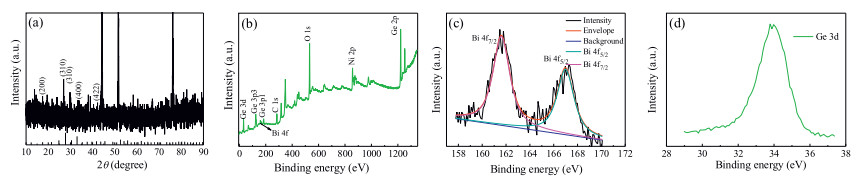
To distinguish the crystallographic structure and composition of the as-prepared product, the XRD pattern of the lotus-stalk Bi4Ge3O12 NSs@NF is presented in Fig. 1a. Three strong and obvious characteristic diffraction peaks located at 44.1°, 51.6°, 76.1° could be indexed to the NF substrate. NF substrate is foam-like nickel metal with highly crystallinity so that its diffraction peaks present three strong and obvious characteristic diffraction peaks. The profiles of other relative weak diffraction peaks, which are well-defined and designated as the (310), (321), (400) and (422) lattice planes of cubic Bi4Ge3O12 (JCPDS card No. 89-1294), could be observed. The cubic Bi4Ge3O12 grown on the Ni foam is difficult to distinguish due to the existence of NF substrate. However, the molar ratio of Bi and Ge in the final products Bi4Ge3O12 is lower than that of raw materials (GeO2:BiI3 = 1:1), it may caused by the partial constituent of the Bi4Ge3O12 with poor crystallinity [42].

|
Download:
|
| Fig. 1. (a) XRD patterns of lotus-stalk Bi4Ge3O12 NSs@NF and standard pattern of JCPDS card No. 89-1294. XPS spectra of lotus-stalk Bi4Ge3O12 NSs@NF: (b) survey spectrum, high resolution of (c) Bi 4f and (d) Ge 3d spectra. | |
The surface detailed chemical composition and the oxidation state of lotus-stalk Bi4Ge3O12 NSs@NF were investigated by XPS. The overall XPS spectrum shown in Fig. 1b indicates that the as-obtained sample is composed of Bi, Ge, O, C and Ni species. The C element presented in the overall spectrum may arise from the organic raw material. The peak of Ni located at 586.6 eV could be assigned to the substrate. Fig. 1c displays the high resolution of Bi 4f spectrum, two peaks locate at 161.6 eV and 166.9 eV could be attributed to Bi 4f7/2 and Bi 4f5/2, respectively, indicating Bi element in the product has +3 valence [44]. As depicted in Fig. 1d, the binding energy of Ge 3d is 33.8 eV, corresponding to Ge4+ state [45-47].
The morphology of hydrothermal-product has a strong relationship with the conditions of hydrothermal reactions, such as compositions of solvent. In order to understand the effect of the compositions of solvent on the morphology, the paralleled experiments were carried out. The NF remains in a 3D grid structure with hierarchical macro-porosity after the hydrothermal reaction (Fig. S1 in Supporting information). Figs. 2a and b show a representative large-area SEM image of the as-prepared product anchored on a NF substrate. The product conducted in the mixture of ethylene glycol and deionized water with a volume ratio of 1:1 is composed of standing nanosheets with a thickness of 10~15 nm. The interval of the nanosheets is 50~300 nm. As presented in Figs. 2c and d, when all of the solutions were replaced by anhydrous ethanol, the product grown much more denser, the interval of the nanosheets become narrower (1~100 nm) and the thickness turned to thinner (5~10 nm). Therefore, the former product presents more advantages including the larger channel for ion transport and the stronger ability to reduce the mechanical stress.

|
Download:
|
| Fig. 2. (a) Low- and (b) high-magnification SEM images of lotus-stalk Bi4Ge3O12 NSs@NF conducted in the equal volume ethylene glycol and deionized water. (c) Low- and (d) high-magnification SEM of lotus-stalk Bi4Ge3O12 NSs@NF conducted in the anhydrous ethanol. (e, f) different magnified TEM and (g) HRTEM images of lotus-stalk Bi4Ge3O12 NSs@NF. (h) SEM image and the corresponding EDX elemental mapping images of lotus-stalk Bi4Ge3O12 NSs@NF. | |
The detailed microstructure of the lotus-stalkBi4Ge3O12 NSs@NF was further investigated by TEM and HRTEM. The lotus-stalk Bi4Ge3O12 interlinked NSs were separated from the NF by ultrasonication in ethanol and then pasted directly onto a copper grid to carry out TEM analysis [10]. As shown in Fig. 2e, the lotus-stalk Bi4Ge3O12 NSs@NF is consisted of ultrathin 2D nanosheets with flake size of about 200 nm. Fig. 2f shows that Bi4Ge3O12 nanosheets stack together with several layers. When the nanosheets were separated from the NF, stacking may occur due to the high surface energy [48]. As depicted in Fig. 2g, HRTEM image reveals the resolved the lattice fringe of 0.574 nm, which is in accordance with the nominal data of (200) plane of cubic Bi4Ge3O12. Additionally, the SEM of the pristine Bi4Ge3O12 powder is illustrated in Fig. S2 (Supporting information), the product shows irregular morphology. In order to clarity the elemental distribution in the nanosheets, the EDS mapping analysis was carried out. As depicts Fig. 2h, all of the EDS elemental mapping images match well with the original SEM image, demonstrating that Bi, Ge and O elements are uniformly distributed throughout the whole scanned area.
In order to explore the reaction kinetics of the lotus-stalk Bi4Ge3O12 NSs@NF electrodes, CV measurements of the electrodes at different scan cycle were recorded and are shown in Fig. 3. Fig. 3a shows the CV curves for the first five cycles of lotus-stalk Bi4Ge3O12 NSs@NF electrode for LIBs, the first reduction curve is quite different from the following four below 1.8 V. In the initial curve, there is a remarkable cathodic peak located at 0.93 V, which is attributed to the decomposition of Bi4Ge3O12 into Bi, Ge, Li2O, as well as the formation of the solid electrolyte interface (SEI) film. Another strong cathodic peak at 0.32 V indicates the alloying reactions of Li-Ge and Li-Bi [49]. In the oxidation scanning, a broad peak at around 0.54 V could be found, which is attribute to the dealloying reaction of Li-Ge [50]. The strong anodic peak at about 1.02 V could be triggered by the de-alloying processes of Li-Bi [51]. The other two weak peaks loaded at 1.34 V and 2.39 V are assigned to the reoxidation of Bi and Ge, respectively [51, 52]. In the subsequent cycles, the reduction peak at 1.52 V is related to the reduction of GeO2 to Ge [52]. The peaks below 0.65 V are contributed to a series of alloying reactions of Ge and Bi with Li. From Fig. 3a, we can found that the last four curves are almost overlap suggesting good cyclability of the electrode. In order to further explore the property of the lotus-stalk Bi4Ge3O12 NSs@NF, CV measurement of NIBs, in which the material act as the bind-free electrode, was conducted and shown in Fig. 3b. In the initial reduction scanning, an obvious cathodic peak located at 1.03 V can be triggered by the deconstruction of Bi4Ge3O12 and a series alloying reactions between Na and Ge, which is in good agreement with the theoretical value of 0.3 V [13]. Subsequently, in the first anodic curve, two peaks discovered at 0.7 V and 1.01 V can be assigned to the de-alloying reaction of NaxGe and Na3Bi [53-55]. Meanwhile, the intensities of peaks of the subsequent cycles turn weak, indicating the formation of SEI film, the decomposition of the electrolyte and other some irreversible reactions upon the first cycle [56]. In the following cycles, the curves are highly overlapped, suggesting the lotus-stalk Bi4Ge3O12 NSs@NF electrode possess high reversibility [50].

|
Download:
|
| Fig. 3. CV curves of lotus-stalk Bi4Ge3O12 NSs@NF electrode: (a) LIBs and (b) NIBs at a scan rate of 0.20 mV/s. Charge/discharge capacities at various current rates of Bi4Ge3O12 electrode: (c) LIBs and (d) NIBs. | |
The rate performance of lotus-stalk Bi4Ge3O12 NSs@NF and the pristine Bi4Ge3O12 powder electrodes for LIBs were evaluated. As shown in Fig. 3c, the lotus-stalk Bi4Ge3O12 NSs@NF electrode delivers capacities of 1426.3, 1283, 915.6, 539.9, 351.4, 251.6 mAh/g at the current densities of 0.3, 0.5, 1, 1.5, 2 and 2.5 A/g, respectively. While the pristine electrode measured at the same condition delivers capacities of 427.8, 333.8, 144.6, 75.7, 52.3, 40.1 mAh/g, respectively. Remarkably, the lotus-stalk Bi4Ge3O12 NSs@NF electrode displays a higher rate capability than that of the pristine one. When used as anodes for NIBs, as shown in Fig. 3d, the lotusstalk Bi4Ge3O12 NSs@NF electrode delivers capacities of 843.8, 774.8, 663.2, 537.8, 435.7, 352.6 mAh/g at the current densities of 0.3, 0.5, 1, 1.5, 2 and 2.5 A/g, respectively.While the pristine electrode measured at the same condition delivers capacities of 421.9, 354.3, 212.4, 91, 47.7, 28.6 mAh/g, respectively. The above-mentioned materials display similar electrochemical behavior: as revealed in Fig. 3d, the product anchored on NF exhibits better rate performance than that of the pristine powder. It is no doubt that the outstanding rate performance of the lotus-stalk Bi4Ge3O12 NSs@NF is attributed to the 3D porous NF frameworks and the ultrathin Bi4Ge3O12 NSs, which provide interconnected electronic conductive pathways, enable large contact area between the active materials and the electrolytes, and shorten the diffusion route of Na+/Li+. EIS measurements were performed with cells before cycling and after running 88 cycles for LIBs and 100 cycles for NIBs to reveal the polarization mechanism of the electrode [57]. The EIS measurements of the two samples were carried out as shown in Fig. S3 (Supporting information). The Nyquist plots are consisted of a semicircle presented at the high frequency related to the charge transfer process and an inclined line located in low frequency region ascribed to the diffusion of Li-ion between the electrode and the electrolyte [58-60]. It can be seen from Fig. S3 that the diameter of the semicircle for the electrode after cycling is obviously narrowed than the fresh cell, corresponding to a faster charge-transfer reaction, which suggested that the conductivity of electrode was improved [50].This could be assigned to the decomposition of the passivation film and the gradually increased surface area from the formation of Li dendrites [61].
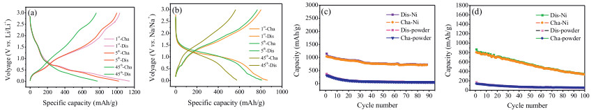
The charge-discharge curves and cycling performance of lotusstalk Bi4Ge3O12 NSs@NF electrode are presented in Fig. 4. The 1st, 5th and 45th cycle discharge–charge voltage curves of the lotus-stalk Bi4Ge3O12 NSs@NF electrode at a constant current density of 0.10 A/g are displayed in Fig. 4a and b. As depicted in Figs. 4a and b, all the charge/discharge curves show plateaus agree with the peaks in the CV. Figs. 4a shows the charge-discharge curves of the lotus-stalk Bi4Ge3O12 NSs@NF electrode for LIBs, which delivered an initial charge and discharge capacity of 1033.1 and 1146.7 mAh/g at 0.10 A/g, respectively, corresponding to a coulombic efficiency (CE) of 90%. The initial irreversible capacity loss is mainly ascribed to the formation of the SEI layer and decomposition of the electrolyte during the first cycle, which is similar to that of reported in other metal oxides and sulfide anode materials of lithium-ion batteries [62]. In addition, the large specific surface area of lotus-stalk Bi4Ge3O12 NSs@NF and the reductive decomposition of the electrolyte also lead to some irreversible capacity loss during the first cycle [63]. In the subsequent cycles, the CE increases to nearly 100%. As presented in Fig. 4c, at the current density of 0.10 A/g, the electrode delivered a capacity of 709 mAh/g, 68.6% of the first cycle's capacity, could be remained after 88 cycles [44]. For comparison, the electrochemical properties of the pristine Bi4Ge3O12 powder were also investigated. While the powder only demonstrated charge and discharge capacity of 57.1 mAh/g and 56.5 mAh/g, respectively. Obviously, the lotus-stalk Bi4Ge3O12 NSs@NF electrode displayed better cycling performance than the pristine one. As illustrated in Fig. 4d, when utilized the above mentioned materials as active material for NIBs, the lotus-stalk Bi4Ge3O12 NSs@NF electrode deliver an initial capacity of 865.5 mAh/g at 0.10 A/g, its capacity could remained at 332.3 mAh/g after 100 cycles (from the first cycle the current was constant at 0.10 A/g). In contrast, the capacity of the pristine Bi4Ge3O12 powder only remained at 50 mAh/g under the same condition. Through a series of comparative experiments, the lotus-stalk Bi4Ge3O12 NSs@NF electrode demonstrates its advantage compared with the pristine one. It should be noted that the cycling capability of lotus-stalk Bi4Ge3O12 NSs@NF in LIBs is better than that of SIBs, which implies the larger diameter of Na+ ions cause more sluggish transportation and larger volume expansion [64].

|
Download:
|
| Fig. 4. Charge-discharge curves of the lotus-stalk Bi4Ge3O12 NSs@NF electrodes at 1st, 5th, and 45th cycle: (a) LIBs and (b) NIBs. Cycling performance of the lotus-stalk Bi4Ge3O12 NSs@NF electrodes vs. the pristine Bi4Ge3O12 electrodes at the same current density of 0.10 A/g: (c) LIBs and (d) NIBs. | |
The excellent electrochemical performance of lotus-stalk Bi4Ge3O12 NSs@NF for LIBs and NIBs can be triggered by the following features. Firstly, the material shows high specific surface area and large pores between the contiguous nanosheets, which can render a large electrode/electrolyte contact area for ion diffusion. Secondly, the ultrathin Bi4Ge3O12 NSs (5~15 nm) anchored on the surface of the NF network greatly shorten the Li+/Na+ ion diffusion distance. Consequently, the diffusion dynamics of ions can be significantly boosted. Thirdly, the NF network can significantly improve the electronic conductivity of the electrodes, resulting in enhanced electrochemical reactivity and reversibility. Lastly, the NF network can buffer the huge volume change of Bi4Ge3O12 during cycling and thus guarantee the structural integrity of Bi4Ge3O12. Therefore, the lotus-stalk Bi4Ge3O12 NSs@NF shows improved cycling stability and rate properties.
In summary, lotus-stalk Bi4Ge3O12 NSs@NF was synthesized via a facial and straight-forward solvothermal route. The strong confinement of lotus-stalk Bi4Ge3O12 NSs@NF to 3D conductive network is the key for achieving stable electrode architecture to tolerant repeatable electrochemical cycles. In addition, the 3D conductive frameworkimproves theelectrical conductivityof the electrode and acts as a buffer matrix to release the volume changes, maintaining theintegrityof theelectrode.Whenused as anodematerialsfor LIBs, lotus-stalk Bi4Ge3O12 NSs@NF showed excellent Li+ storage performance with a high reversible capacity of 709 mAh/g after 88 cycles. For NIBs test, the material exhibited high reversible capacity of 332.3 mAh/g after 100 cycles. The outstanding electrochemical performances promise the lotus-stalk Bi4Ge3O12 NSs@NF as a potential candidate for next-generation energy storage devices. Moreover, this facile method which takes the advantages of nanostructure design and regulation pave the way to fabrication other advanced materials for energy related areas.
AcknowledgmentsThis study was supported by the National Natural science Foundation of China (No. U1804138), the Science Foundation of Henan Province (No. 162300410209), the Key Scientific Research Project of High Schools in Henan Province (No.17A480009) and the Special Key Research Program of Henan Province (No. 182102210488).
Appendix A. Supplementary dataSupplementary material related to this article can be found, in the online version, at doi:https://doi.org/10.1016/j.cclet.2019.03.005.
| [1] |
Q. Wang, C. Zhao, Y. Lu, et al., Small 13 (2017) 1701835. DOI:10.1002/smll.201701835 |
| [2] |
X. Li, J. Ni, S.V. Savilov, L. Li, Chem. -Eur. J. 24 (2018) 13719-13727. DOI:10.1002/chem.201801574 |
| [3] |
L. Wang, J.L. Shi, H. Su, et al., Small 14 (2018) 1800887. DOI:10.1002/smll.v14.34 |
| [4] |
F. Li, Z. Zhou, Small 14 (2017) 1702961. |
| [5] |
W. Wei, J L X., M T Xu., et al., Sci. China Chem. 61 (2018) 515-525. |
| [6] |
W. Wei, A.H. Tian, F.F. Jia, et al., RSC Adv. 6 (2016) 87440-87445. DOI:10.1039/C6RA14819K |
| [7] |
C. Wu, X. Tong, Y. Ai, et al., Nano-Micro Lett. 10 (2018) 40. DOI:10.1007/s40820-018-0194-4 |
| [8] |
H. Wang, W. Yu, J. Shi, et al., Electrochim. Acta 188 (2016) 103-110. DOI:10.1016/j.electacta.2015.12.002 |
| [9] |
Q. Li, Z. Zhang, S. Dong, et al., Part. Part. Syst. Charact. 34 (2017) 1600115. DOI:10.1002/ppsc.v34.3 |
| [10] |
G. Gao, Y. Xiang, S. Lu, et al., Nanoscale 10 (2018) 921-929. DOI:10.1039/C7NR05407F |
| [11] |
Y. Wu, Z. Wen, J. Li, Adv. Mater. 23 (2011) 1126-1129. DOI:10.1002/adma.201003713 |
| [12] |
H. Yu, Y.G. So, Y. Ren, et al., J. Am. Chem. Soc. 140 (2018) 15279-15289. DOI:10.1021/jacs.8b07858 |
| [13] |
J. Liang, C. Yuan, H. Li, et al., Nano-Micro Lett. 10 (2017) 21. |
| [14] |
H. Yu, Y. Qian, M. Otani, et al., Energy Environ. Sci. 7 (2017) 1068. |
| [15] |
M. Li, Z. Zhang, X. Ge, et al., Chem. Eng. J. 331 (2018) 203-210. DOI:10.1016/j.cej.2017.08.077 |
| [16] |
H. Yu, Y.G. So, A. Kuwabara, et al., Nano Lett. 16 (2016) 2907-2915. DOI:10.1021/acs.nanolett.5b03933 |
| [17] |
W. Wei, Z. Wang, Z. Liu, et al., J. Power Sources 238 (2013) 376-387. DOI:10.1016/j.jpowsour.2013.03.173 |
| [18] |
Z. Lin, X. Guo, H. Yu, Nano Energy 41 (2017) 646-653. DOI:10.1016/j.nanoen.2017.10.021 |
| [19] |
Y. Xie, H. Zhao, H. Cheng, et al., Appl. Energy 175 (2016) 522-528. DOI:10.1016/j.apenergy.2016.03.085 |
| [20] |
Y. Fu, Q. Wei, G. Zhang, S. Sun, Adv. Energy Mater. 8 (2018) 1703058. |
| [21] |
W.J. Wang, H.B. Zhao, A.B. Yuan, et al., Acta Phys. Chim. Sin. 30 (2014) 1113-1120. |
| [22] |
G. Zou, H. Hou, P. Ge, et al., Small 14 (2018) 1702648. DOI:10.1002/smll.v14.3 |
| [23] |
X. Ma, K. An, J. Bai, H. Chen, Sci. Rep. 7 (2017) 162. DOI:10.1038/s41598-017-00202-y |
| [24] |
C. Zhao, Y. Lu, Y. Li, et al., Small Methods 1 (2017) 1600063. DOI:10.1002/smtd.v1.5 |
| [25] |
Y. Kim, K.H. Ha, S.M. Oh, K.T. Lee, Chem. -Eur. J. 20 (2014) 11980-11992. DOI:10.1002/chem.v20.38 |
| [26] |
S. Lu, H. Wang, J. Zhou, et al., Nanoscale 9 (2017) 1184-1192. DOI:10.1039/C6NR07868K |
| [27] |
D.T. Ngo, R.S. Kalubarme, H.T. Le, et al., Nanoscale 7 (2015) 2552-2560. DOI:10.1039/C4NR05541A |
| [28] |
W. Wei, L.X. Song, L. Guo, Chin. Chem. Lett. 26 (2015) 124-128. DOI:10.1016/j.cclet.2014.09.023 |
| [29] |
Z. Hu, S. Zhang, C. Zhang, G. Cui, Coord. Chem. Rev. 326 (2016) 34-85. DOI:10.1016/j.ccr.2016.08.002 |
| [30] |
W. Wei, F.F. Jia, K.F. Wang, P. Qu, Chin. Chem. Lett. 28 (2017) 324-328. DOI:10.1016/j.cclet.2016.09.003 |
| [31] |
M. Lao, Y. Zhang, W. Luo, et al., Adv. Mater. 29 (2017) 1700622. DOI:10.1002/adma.v29.48 |
| [32] |
L. Zhang, W. He, K. Shen, et al., J. Alloys Compd. 760 (2018) 84-90. DOI:10.1016/j.jallcom.2018.05.119 |
| [33] |
Y. Jiang, Y. Song, Z. Pan, et al., ACS Nano 12 (2018) 5011-5020. DOI:10.1021/acsnano.8b02352 |
| [34] |
Z. Wen, Q. Wang, Q. Zhang, J. Li, Adv. Funct. Mater. 17 (2007) 2772-2778. DOI:10.1002/(ISSN)1616-3028 |
| [35] |
Q. Ma, W. Wang, P. Zeng, Z. Fang, Langmuir 33 (2017) 2141-2147. DOI:10.1021/acs.langmuir.6b04444 |
| [36] |
X. Liu, N. Lin, W. Cai, et al., Dalton Trans. 47 (2018) 7402-7406. DOI:10.1039/C8DT01060A |
| [37] |
N. Lin, T. Li, Y. Han, et al., ACS Appl. Mater. Interfaces 10 (2018) 8399-8404. DOI:10.1021/acsami.8b00567 |
| [38] |
W. Wei, H. Wang, A. Tian, et al., Nanoscale 10 (2018) 6872-6877. DOI:10.1039/C8NR00153G |
| [39] |
K. Shen, N. Lin, T. Xu, Y. Han, Y. Qian, R. Soc. Open Sci. 5 (2018) 171477. DOI:10.1098/rsos.171477 |
| [40] |
J. Li, B. Liu, M. Li, et al., Eur. J. Inorg. Chem. 2018 (2018) 3036-3040. |
| [41] |
Q. Li, X. Miao, C. Wang, L. Yin, J. Mater. Chem. A 3 (2015) 21328-21336. DOI:10.1039/C5TA04648C |
| [42] |
D. Ma, X. Shi, A. Hu, Nanomaterials 6 (2016) 218. DOI:10.3390/nano6110218 |
| [43] |
T. Jin, Q. Han, Y. Wang, L. Jiao, Small 14 (2018) 1703086. DOI:10.1002/smll.v14.2 |
| [44] |
Z. Deng, T. Liu, T. Chen, et al., ACS Appl. Mater. Interfaces 9 (2017) 12469-12477. DOI:10.1021/acsami.7b00996 |
| [45] |
J. Han, J. Qin, L. Guo, et al., Appl. Surf. Sci. 427 (2018) 670-679. |
| [46] |
R. Ge, S. Wu, Y. Du, et al., Carbon 107 (2016) 352-360. DOI:10.1016/j.carbon.2016.06.011 |
| [47] |
O.A. Qun, Z. Zhiwei, D. Shihua, et al., Part. Part. Syst. Charact. 34 (2017) 1600115. DOI:10.1002/ppsc.v34.3 |
| [48] |
Y. Son, M. Park, Y. Son, et al., Nano Lett. 14 (2014) 1005-1010. DOI:10.1021/nl404466v |
| [49] |
X. Ma, Y. Zhou, M. Chen, L. Wu, Small 13 (2017) 1700403. DOI:10.1002/smll.v13.20 |
| [50] |
W. Wei, F. Jia, P. Qu, et al., Nanoscale 9 (2017) 3961-3968. DOI:10.1039/C7NR00599G |
| [51] |
Z. Song, H. Zhang, K. Feng, et al., Dalton Trans. 47 (2018) 7739-7746. DOI:10.1039/C8DT00910D |
| [52] |
X. Liu, X. Ma, J. Wang, et al., RSC Adv. 6 (2016) 107040-107048. DOI:10.1039/C6RA14289C |
| [53] |
H. Yin, M.L. Cao, X.X. Yu, et al., Mater. Chem. Front. 1 (2017) 1615-1621. DOI:10.1039/C7QM00128B |
| [54] |
L. Wang, C. Wang, F. Li, et al., Chem. Commun. (Camb.) 54 (2017) 38-41. |
| [55] |
J. Qiu, S. Li, X. Su, et al., Chem. Eng. J. 320 (2017) 300-307. DOI:10.1016/j.cej.2017.03.054 |
| [56] |
Q. Sun, L. Fu, C. Shang, Scanning 2017 (2017) 6. |
| [57] |
T. Wu, Z. Wen, C. Sun, et al., J. Mater. Chem. A 6 (2018) 12623-12629. DOI:10.1039/C8TA01883A |
| [58] |
H. Qiu, L. Zeng, T. Lan, et al., J. Mater. Chem. A 3 (2015) 1619-1623. DOI:10.1039/C4TA05212A |
| [59] |
J. Feng, C. Wang, Y. Qian, Mater. Lett. 122 (2014) 327-330. DOI:10.1016/j.matlet.2014.02.081 |
| [60] |
X. Li, X. Sun, Z. Gao, et al., ChemSusChem 11 (2018) 1549-1557. DOI:10.1002/cssc.v11.9 |
| [61] |
Q. Li, S. Zhu, Y. Lu, Adv. Funct. Mater. 27 (2017) 1606422. DOI:10.1002/adfm.201606422 |
| [62] |
X. Zhou, L. Yu, X.W.D. Lou, Adv. Energy Mater. 6 (2016) 1600451. DOI:10.1002/aenm.201600451 |
| [63] |
Y. Zhong, B. Li, S. Li, et al., Nano-Micro Lett. 10 (2018) 56. DOI:10.1007/s40820-018-0209-1 |
| [64] |
W. Luo, F. Li, J.J. Gaumet, et al., Adv. Energy Mater. 8 (2018) 1703237. DOI:10.1002/aenm.v8.19 |