 2019, Vol. 30


b Department of Physics, The Chinese University of Hong Kong, Hong Kong 999077, China;
c Department of Electrical and Computer Engineering, Ben-Gurion University of the Negev, Beer-Sheva 8410501, Israel
In recent years, organic solar cells (OSCs) whose active layer is generally bulk heterojunction (BHJ) composed of an electron donor and an electron acceptor, have inspired intensive interests from academia to industry because of their particular advantages, such as flexibility, light weight, color tunability, and compatibility with large-area printing [1-3]. Benefiting from the rapid development of non-fullereneacceptors[4-7], the recent photovoltaic performances of OSCs have been enhanced dramatically, with the championpower conversion efficiencies (PCEs) of exceeding 14% and 17% for the single-junction and tandem devices, respectively [8-10].
However, there is still a long way to realize the commercialization of OSCs. For example, at present, almost all high-efficiency OSCs reported adopt a donor-acceptor (D-A) copolymer donor, such as poly{[2, 6'-4, 8-di(5-ethylhexylthienyl)benzo[1, 2-b:4, 5-b'] dithiophene]-alt-3-fluoro-2[(2-ethylhexyl)carbonyl]thieno[3, 4-b] thiophenediyl} (PTB7-Th) [11-15], and poly{[2, 6'-4, 8-di(5-ethylhexylthienyl)benzo[1, 2-b:4, 5-b']dithiophene]-alt-[5, 5-(1', 3'-di-2-thienyl-5', 7'-bis(2-ethylhexyl)benzo[1', 2'-c:4', 5'-c']dithiophene-4, 8-dione)]} (PBDB-T) [16-21]. With the alternate structure of the donor and acceptor, this kind of polymer would possess narrower bandgap and broader light absorptions, which is beneficial to harvest more solar photons for the corresponding OSCs [22-24]. However, the nature of complicated synthesis and difficulties to scale-up may hinder their future commercial applications. In contrast to these polymers, homo-polymer poly(3-hexylthiophene) (P3HT), one of the most commonly used and well-studied polymers in the field of OSCs [25-27], is the only polymer that is available in quantities of over 10 kg so far. Besides, P3HT is suitable for low-cost solution coating techniques (e.g., roll-to-roll largeproduction printing) [28] and relatively stable [29, 30]. All these advantages make P3HT the promising donor for the future commercial OSCs. However, the PCEs of P3HT-based OSCs lag far behind those of D-A copolymer based counterparts.
The relatively poor performances of P3HT-based OSCs can be mainly ascribed to the high-lying energy levels and the wide bandgap of P3HT. It is reported that the bandgap of P3HT is ~2.0 eV, and its lowest unoccupied molecular orbital (LUMO) and highest occupied molecular orbital (HOMO) energy levels are -3.0 and -5.0 eV, respectively [31]. Thus, P3HT can only absorb the sunlight below 650 nm, which is only a small fraction of solar irradiation. Furthermore, the widely used acceptors in OSCs usually own much lower energy levels than P3HT, leading to large energy loss (Eloss) for the resultant devices. For instance, [6, 6]-phenyl-C61-butyric acid methyl ester, PC61BM, has the lower-lying LUMO of -3.91 eV so that the P3HT:PC61BM OSCs only give an open-circuit voltage (VOC) of about 0.60 V, corresponding to a huge Eloss of ~1.40 eV [32]. On the contrary, indene-C60 bisadduct (ICBA) shows a LUMO 0.17 eV higher than that of PC61BM, providing the better PCE with a high VOC of 0.84 V for the P3HT:ICBA devices [33, 34]. Unfortunately, the above fullerene acceptors can hardly improve the lightharvesting capability of P3HT-based OSCs due to their weak absorptions even in ultraviolet and visible regions.
Therefore, researchers have devoted research interests into the design of non-fullerene acceptors, which owns easily tuned energy levels and strong ultraviolet-to-visible-near infrared (UV-to-NIR) absorptions, for achieving efficient P3HT-based OSCs [35-38]. Besides, a few investigations have reported that some OSCs adopting non-fullerene acceptors can achieve higher VOCs with lower voltage losses [39-41]. In 2016, Holliday et al. reported two A-D-A type non-fullerene acceptors, O-IDTBR and EH-IDTBR [42], which used indacenodithiophene (IDT) and benzothiadiazole linked by a double bond with 3-ethyl-2-thioxothiazolidin-4-one as the electron-donating (D) core and the electron-accepting (A) end-groups, respectively. Due to the intramolecular charge transfer (ICT) effect from D core to A groups, O-IDTBR and EH-IDTBR possessed intense absorption bands extending to 760 nm and 738 nm, respectively, which were both complementary to that of P3HT. And the morphological properties of the two acceptors were well-matched with P3HT, too. Consequently, the P3HT:O-IDTBR and P3HT:EH-IDTBR OSCs yielded the high PCEs of 6.3% and 6.0%, respectively, which were the best efficiencies reported for fullerene-free P3HT-based devices at that time. Nevertheless, the LUMO energy levels of O-IDTBR and EH-IDTBR were -3.88 eV and -3.90 eV, respectively, still much lower than that of P3HT, which caused low VOCs of 0.72 V and 0.76 V for the corresponding OSCs.
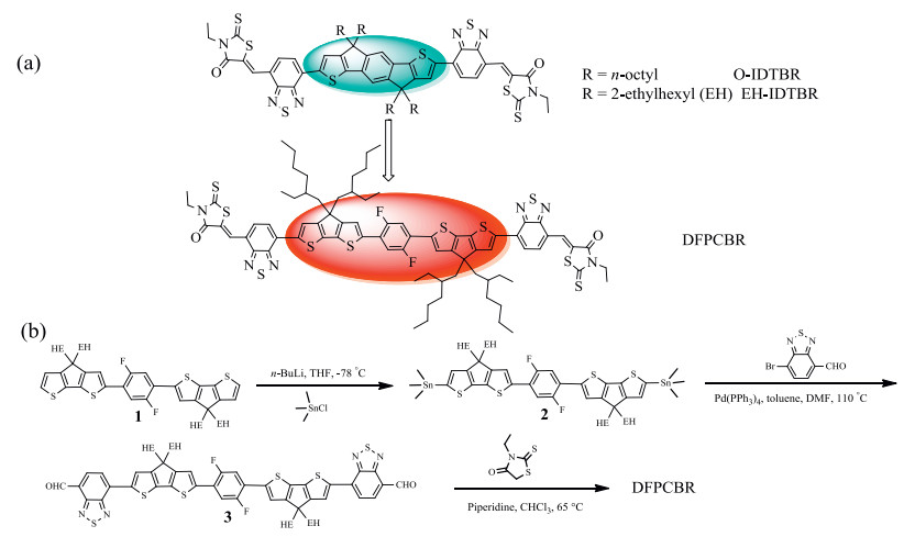
Taking the above considerations into accounts, in this work, we design a new acceptor DFPCBR to pair with P3HT. As shown in Scheme 1a, we choose a stronger electron-donating and larger π-conjugated D core to replace IDT in EH-IDTBR, and A end-groups of benzothiadiazole connected with 3-ethyl-2-thioxothiazolidin- 4-one are preserved. Our D core contains a 2, 5-difluorobenzene (DFB) ring attached to a cyclopentadithiophene (CPDT) moiety at each side. Because the F…H noncovalent interaction between the fluorine atoms on DFB group and the hydrogen atoms on adjacent CPDT units locks the molecular conformation [19, 20, 43, 44], DFPCBR owns a planar geometry similar as O-IDTBR and EH-IDTBR. Thus, DFPCBR's morphological property may also be compatible with P3HT. Moreover, DFPCBR is expected to show red-shifted absorptions and high-lying energy levels, to enhance the light-harvesting ability and mitigate the energy loss for the P3HT-based OSCs. Then, the absorptions, energy levels, and photovoltaic property of DFPCBR are investigated in detail, to prove the rationale of our molecular design.

|
Download:
|
| Scheme 1. (a) The chemical structures of O-IDTBR, EH-IDTBR, and DFPCBR. (b) The synthetic route of DFPCBR. | |
As shown in the Scheme 1b, DFPCBR is synthesized through routine reactions, and 1H NMR, 13C NMR and MALDI-TOF MS spectroscopies are used to characterized the chemical structure of DFPCBR (Figs. S1-S3 in Supporting information, respectively. According to the TGA curve, it revealed that DFPCBR shows good thermal stability with a decomposition temperature (Td, 5% weight loss) at 399 ℃ under nitrogen atmosphere. From the DSC curve, one crystallization peak at 168 ℃ and two melting peaks at 237 ℃ and 244 ℃ together with a glass transition at about 125 ℃ are found, indicating that DFPCBR possesses good crystallinity.
To investigate the optical properties, the UV-vis absorption spectra of DFPCBR in solution and film are measured (Fig. 1). It observed that DFPCBR has a maximum molar extinction coefficient of 1.32 × 10⁻⁵ L mol-1 cm-1 at 647 nm in CHCl3 solution. DFPCBR film exhibits intense absorptions in the range of 500-780 nm, which are broader and more red-shifted than those of its solution, implying the existence of intermolecular π-π actions in the solid state. The optical bandgap of DFPCBR is estimated to be 1.59 eV from the absorption edge (782 nm). As expected, DFPCBR owns a narrower bandgap than O-IDTBR (1.63 eV) and EH-IDTBR (1.68 eV) [42], which is in favor of harvesting more sunlight for the resultant OSCs.

|
Download:
|
| Fig. 1. UV–vis absorption spectra of DFPCBR in CHCl3 solution, DFPCBR film and P3HT film. | |
Cyclic voltammetry (CV) is used to characterize the energy levels of DFPCBR (Fig. S6 in Supporting information). According to the equations of LUMO = -e (φred + 4.8) (eV) and HOMO = -e (φox + 4.8) (eV), in which φred and φox are the onsets of reduction and oxidation potentials versus FeCP20/+ (the couple of neutral ferrocene and its cation whose absolute energy level is 4.8 eV below vacuum), respectively, the LUMO and HOMO energy levels of DFPCBR are calculated to be -3.59 eV and -5.12 eV, respectively. These results prove that, compared to O-IDTBR and EH-IDTBR, DFPCBR has higher-lying energy levels close to those of P3HT (-3.0 eV and -5.0 eV), which is beneficial to reduce the energy loss for the P3HT-based devices.
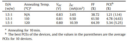
Since DFPCBR possesses the absorptions and energy levels matched well with P3HT, OSCs with a structure of ITO/ZnO/PFN/P3HT:DFPCBR/MoO3/Ag are fabricated and studied. To find the optimal conditions, we first vary the weight ratios of donor (D, P3HT) and acceptor (A, DFPCBR) from 0.8:1 to 1.75:1, and identify the best D/A weight ratio of 1.5:1 (Table S1 in Supporting information). Post treatments, thermal annealing and chloronaphthalene (CN) additive, are applied to further optimize device performance. Instead of the little effect of CN additive, annealing can enhance the device performance. After annealing at 120 ℃ for 10 min, the highest PCE of 5.34% is achieved with a VOC of 0.80 V, a short-circuit current density (JSC) of 10.39 mA/cm2 and a fill factor (FF) of 0.64 for the P3HT:DFPCBR OSCs (Table 1). Obviously, the DFPCBR-based devices show a much smaller Eloss of 0.79 eV than those of O-IDTBR (0.91 eV) and EH-IDTBR (0.92 eV) [42], thereby, providing a higher VOC even though DFPCBR has the narrower bandgap than those of O-IDTBR and EH-IDTBR.
|
|
Table 1 Photovoltaic parameters of the OSCs based on P3HT:DFPCBR under the illumination of AM 1.5 G, 100 mW/cm2. |
Fig. 2a shows the J-V curves of the P3HT:DFPCBR OSCs obtained under different conditions. The as-cast device shows a comparatively higher VOC of 0.83 V, but a low JSC of 3.65 mA/cm2 and a poor FF of 0.38, which leads to a low PCE of 1.21%. When the device is annealed at 120 ℃ for 10 min, the VOC declines gently to 0.80 V, but the JSC and FF increase sharply to 10.39 mA/cm2 and 64.39%, respectively. As a result, the PCE increases to 5.34%.

|
Download:
|
| Fig. 2. J-V curves (a) and EQE spectra (b) of the P3HT:DFPCBR OSCs with and without thermal annealing at 120 ℃ for 10 min. | |
The external quantum efficiency (EQE) spectra of the above OSCs are shown in the Fig. 2b. For the as-cast device, the EQE values are very low, which is consistent with the small JSC and the bad PCE. Through the treatment of annealing, the EQE responses are improved significantly in the broad range of 300-780 nm, suggesting that both P3HT and DFPCBR contribute to the photocurrents in OSCs.
Besides, we observe that the photovoltaic performances of these devices are insensitive to the thickness of the active layers. The PCE values changed only 15% when varying the thickness of the active layer from 100 nm to 240 nm (Fig. S7 and Table S2 in Supporting information). Even the active layer is as thick as 320 nm, 78% of the best PCE, corresponding to a PCE of 4.14%, is maintained, which is rarely reported for fullerene-free P3HT-based OSCs, suggesting that DFPCBR has the potential applicable in commercial OSCs in the future.
The charge carrier mobilities of P3HT:DFPCBR blended films are investigated by the space-charge-limited current (SCLC) method, using a structure of ITO/PEDOT:PSS/P3HT:DFPCBR/MoO3/Ag for hole-only devices, and a structure of ITO/ZnO/PFN/P3HT:DFPCBR/PFN/Al for electron-only devices, respectively. From Fig. S8 in Supporting information, for the as-cast P3HT:DFPCBR film, hole and electron mobilities (μh and μe) are obtained as 2.7 × 10⁻⁵ cm2 V-1 s-1 and 5.6 × 10⁻⁶ cm2 V-1 s-1, respectively. After annealed at 120 ℃ for 10 min, the P3HT:DFPCBR film owns an increased μh (8.6 × 10⁻⁵ cm2 V-1 s-1) and μe (1 × 10⁻⁵ cm2 V-1 s-1), which is in accordance with the increased JSC and the high FF for the annealed device.
The molecular arrangements of donor and acceptor in pristine and blended films are investigated by grazing-incidence wideangle X-ray scattering (GIWAXS) measurements. The obtained two-dimensional (2D) scattering patterns and the corresponding out-of-plane and in-plane intensity profiles are presented in Fig. 3. We observe that, the DFPCBR film annealed at 120 ℃ for 10 min shows a weak peak at 0.50 Å-1 in the out-of-plane direction (Fig. 3a) because the crystallization temperature of DFPCBR is about 168 ℃ as shown in the DSC curve (Fig. S5 in Supporting information). The annealed pure P3HT film exhibits a highly ordered structure, with strong (100), (200), and (300) peaks at 0.38, 0.76, and 1.14 Å-1, respectively, in the out-of-plane direction, suggesting that P3HT prefers to adopt edge-on molecular arrangements (Fig. 3b). The high crystallinity of P3HT is preserved in the as-cast P3HT-DFPCBR blended film, instead, the diffraction peak of DFPCBR can not be observed (Fig. 3c). After the blended film is annealed at 120 ℃ for 10 minutes, the diffraction peak at 0.50 Å-1 for DFPCBR reappears in the out-of-plane direction, implying that the crystallinity of DFPCBR is improved to some extent (Figs. 3d and e). In the meantime, it is found that there are more face-on oriented P3HT domains in the blended film than in the pristine film, and the π-π stacking diffraction peak of P3HT shifts from 1.65 Å-1 (d = 3.80 Å) of the as-cast blended film to 1.67 Å-1 (d = 3.76 Å) of the annealed blended film, indicating denser molecular packing of P3HT (Fig. 3f). So, the thermal annealing enhances both electron and hole mobilities, which is in accordance with the observed trend of device performance improvement.

|
Download:
|
| Fig. 3. 2D GIWAXS images of (a) DFPCBR film annealed at 120 ℃ for 10 min, (b) P3HT film annealed at 120 ℃ for 10 min, (c) the as-cast P3HT:DFPCBR blended film, (d) the P3HT:DFPCBR blended film annealed at 120 ℃ for 10 min. 1D out-of-plane (e) and in-plane (f) X-ray profiles extracted from GIWAXS patterns. The circles in (e) mark the diffraction peak at 0.50 Å-1 for DFPCBR. | |
The morphologies of P3HT:DFPCBR blended films are further investigated by atomic force microscope (AFM). The relevant images are shown in Fig. S9 (Supporting information). We observe that, the as-cast blended film is relatively smooth with a root mean square (RMS) roughness of 0.74 nm. For the blended film annealed at 120 ℃ for 10 min, the RMS roughness increases to 2.59 nm because of the improved crystallinity.
In conclusion, we design and synthesize a new non-fullerene acceptor, DFPCBR, by adopting a strong electron-donating and large π-conjugated central core. DFPCBR shows more red-shifted absorptions and higher-lying enery levels well-matched with P3HT. After proper optimizations, the P3HT:DFPCBR OSCs provide the best PCE of 5.34% with the reduced energy loss of 0.79 eV. Furthermore, even though the thickness of the active layer is increased dramatically, the PCEs of the OSCs are basically unchangable. Even if the thickness reach 320 nm, ~80% of the best PCE is achieved. With these advantages of small energy loss and thickness insensitivity for P3HT-DFPCBR based solar cells, DFPCBR may be promising for the future commercial applications.
AcknowledgmentsThis work is supported by the National Natural Science Foundation of China (Nos. 21875216, 21734008, 21474088, 51473142, 51561145001, 51620105006, 61721005) and Zhejiang Province Science and Technology Plan (No. 2018C01047). X. Lu and T.-K. Lau acknowledge the financial support from Research Grant Council of Hong Kong (General Research Fund No.14314216, CUHK Direct Grant No. 4053227).
Appendix A. Supplementary dataSupplementary material related to this article can befound, inthe online version, at doi:https://doi.org/10.1016/j.cclet.2019.01.010.
| [1] |
G. Yu, J. Gao, J.C. Hummelen, F. Wudl, A.J. Heeger, Science 270 (1995) 1789-1791. DOI:10.1126/science.270.5243.1789 |
| [2] |
B. Kippelen, J. L. Brédas, Energy Environ. Sci. 2 (2009) 251-261. DOI:10.1039/b812502n |
| [3] |
G. Li, R. Zhu, Y. Yang, Nat. Photonics 6 (2012) 153-161. DOI:10.1038/nphoton.2012.11 |
| [4] |
C.B. Nielsen, S. Holliday, H.Y. Chen, S.J. Cryer, I. McCulloch, Acc. Chem. Res. 48 (2015) 2803-2812. DOI:10.1021/acs.accounts.5b00199 |
| [5] |
S. Li, Z. Zhang, M. Shi, C.Z. Li, H. Chen, Phys. Chem. Chem. Phys. 19 (2017) 3440-3458. DOI:10.1039/C6CP07465K |
| [6] |
S. Li, W. Liu, C.Z. Li, M. Shi, H. Chen, Small 13 (2017) 1701120. DOI:10.1002/smll.v13.37 |
| [7] |
G. Sauvé, R. Fernando, J. Phys. Chem. Lett. 6 (2015) 3770-3780. DOI:10.1021/acs.jpclett.5b01471 |
| [8] |
H. Zhang, H. Yao, J. Hou, et al., Adv. Mater. 30 (2018) 1800613. DOI:10.1002/adma.v30.28 |
| [9] |
L. Meng, Y. Zhang, X. Wan, et al., Science 361 (2018) 1094-1098. DOI:10.1126/science.aat2612 |
| [10] |
Z. Xiao, X. Jia, L. Ding, Sci. Bull. 62 (2017) 1562-1564. DOI:10.1016/j.scib.2017.11.003 |
| [11] |
Q. Wan, X. Guo, Z. Wang, et al., Adv. Funct. Mater. 26 (2016) 6635-6640. DOI:10.1002/adfm.v26.36 |
| [12] |
Y. Lin, J. Wang, Z.G. Zhang, et al., Adv. Mater. 27 (2015) 1170-1174. DOI:10.1002/adma.201404317 |
| [13] |
S. Li, W. Liu, C.Z. Li, et al., J. Mater. Chem. A 4 (2016) 10659-10665. DOI:10.1039/C6TA04232E |
| [14] |
M. Li, Y. Liu, W. Ni, et al., J. Mater. Chem. A 4 (2016) 10409-10413. DOI:10.1039/C6TA04358E |
| [15] |
S. Li, W. Liu, C.Z. Li, et al., J. Mater. Chem. A 4 (2016) 14983-14987. DOI:10.1039/C6TA07368A |
| [16] |
D. Qian, L. Ye, M. Zhang, et al., Macromolecules 45 (2012) 9611-9617. DOI:10.1021/ma301900h |
| [17] |
W. Zhao, D. Qian, S. Zhang, et al., Adv. Mater. 28 (2016) 4734-4739. DOI:10.1002/adma.v28.23 |
| [18] |
S. Li, L. Ye, W. Zhao, et al., Adv. Mater. 28 (2016) 9423-9429. DOI:10.1002/adma.201602776 |
| [19] |
S. Li, L. Zhan, F. Liu, et al., Adv. Mater. 30 (2018) 1705208. DOI:10.1002/adma.201705208 |
| [20] |
N. Wang, L. Zhan, S. Li, et al., Mater. Chem. Front. 2 (2018) 2006-2012. DOI:10.1039/C8QM00318A |
| [21] |
N. Qiu, H. Zhang, X. Wan, et al., Adv. Mater. 29 (2017) 1604964. DOI:10.1002/adma.201604964 |
| [22] |
H. Bin, Z.G. Zhang, L. Gao, et al., J. Am. Chem. Soc. 138 (2016) 4657-4664. DOI:10.1021/jacs.6b01744 |
| [23] |
W. Zhao, S. Li, H. Yao, et al., J. Am. Chem. Soc. 139 (2017) 7148-7151. DOI:10.1021/jacs.7b02677 |
| [24] |
Y. Jin, Z. Chen, S. Dong, et al., Adv. Mater. 28 (2016) 9811-9818. DOI:10.1002/adma.201603178 |
| [25] |
M.T. Dang, L. Hirsch, G. Wantz, Adv. Mater. 23 (2011) 3597-3602. DOI:10.1002/adma.201100792 |
| [26] |
C.J. Mulligan, M. Wilson, G. Bryant, et al., Sol. Energy Mater. Sol. Cells 120 (2014) 9-17. DOI:10.1016/j.solmat.2013.07.041 |
| [27] |
R. Po, A. Bernardi, A. Calabrese, et al., Energy Environ. Sci. 7 (2014) 925-943. DOI:10.1039/c3ee43460e |
| [28] |
J.H. Bannock, S.H. Krishnadasan, A.M. Nightingale, et al., Adv. Funct. Mater. 23 (2013) 2123-2129. DOI:10.1002/adfm.v23.17 |
| [29] |
M. Jorgensen, K. Norrman, S.A. Gevorgyan, et al., Adv. Mater. 24 (2012) 580-612. DOI:10.1002/adma.201104187 |
| [30] |
M. Manceau, S. Chambon, A. Rivaton, et al., Sol. Energy Mater. Sol. Cells 94 (2010) 1572-1577. DOI:10.1016/j.solmat.2010.03.012 |
| [31] |
B. Xiao, A. Tang, L. Cheng, et al., Sol. RRL 1 (2017) 1700166. DOI:10.1002/solr.201700166 |
| [32] |
M.H. Chen, J. Hou, Z. Hong, et al., Adv. Mater. 21 (2009) 4238-4242. DOI:10.1002/adma.v21:42 |
| [33] |
Y. He, H.Y. Chen, J. Hou, Y. Li, J. Am. Chem. Soc. 132 (2010) 1377-1382. DOI:10.1021/ja908602j |
| [34] |
G. Zhao, Y. He, Y. Li, Adv. Mater. 22 (2010) 4355-4358. DOI:10.1002/adma.v22:39 |
| [35] |
Y. Wu, H. Bai, Z. Wang, et al., Energy Environ. Sci. 8 (2015) 3215-3221. DOI:10.1039/C5EE02477C |
| [36] |
S. Li, W. Liu, M. Shi, et al., Energy Environ. Sci. 9 (2016) 604-610. DOI:10.1039/C5EE03481G |
| [37] |
S. Li, J. Yan, C.Z. Li, et al., J. Mater. Chem. A 4 (2016) 3777-3783. DOI:10.1039/C6TA00056H |
| [38] |
F. Liu, J. Zhang, Z. Zhou, et al., J. Mater. Chem. A 5 (2017) 16573-16579. DOI:10.1039/C7TA05108E |
| [39] |
J. Zhang, Y. Li, J. Huang, et al., J. Am. Chem. Soc. 139 (2017) 16092-16095. DOI:10.1021/jacs.7b09998 |
| [40] |
S. Chen, Y. Liu, L. Zhang, et al., J. Am. Chem. Soc. 139 (2017) 6298-6301. DOI:10.1021/jacs.7b01606 |
| [41] |
J. Yu, J.L. Ornelas, Y. Tang, et al., ACSAppl. Mater. Interfaces 9 (2017) 42167-42178. DOI:10.1021/acsami.7b11863 |
| [42] |
S. Holliday, R.S. Ashraf, A. Wadsworth, et al., Nat. Commun. 7 (2016) 11585. DOI:10.1038/ncomms11585 |
| [43] |
T.L. Nguyen, H. Choi, S.J. Ko, et al., Energy Environ. Sci. 7 (2014) 3040-3051. DOI:10.1039/C4EE01529K |
| [44] |
A.C. Stuart, J.R. Tumbleston, H. Zhou, et al., J. Am. Chem. Soc. 135 (2013) 1806-1815. DOI:10.1021/ja309289u |