 2019, Vol. 30


Huge emissions of industrial wastewater have resulted in the negative influence to environment and human's life. It has become a serious problem need to be resolved urgently. At present, there are plenty of conventional solutions including chemical, physical and biological methods have been applied into industrial wastewater treatment. However, the vast majority of these solutions cannot achieve the excellent treatment efficiency due to the existence of toxic and persistent organic compounds in the wastewater [1].
In recent years, advanced oxidation processes (AOPs) including Fenton [2], photo catalysis [3] or ozonation [4, 5] have been reported widely. Fenton catalytic oxidation, which can be divided into homogeneous and heterogeneous Fenton process, is considered as an effective and more excellent solution for the removal of organic compounds in the industrial wastewater among AOPs [6]. In the homogeneous Fenton process, the dissociative ferrous ion can react with hydrogen peroxide to generate hydroxyl radicals (·OH) with a strong oxidizing property, which would decompose the organic compounds in industrial wastewater into CO2 and H2O [7]. Although the homogeneous Fenton process is efficacious for the degradation of pollutants in the wastewater, it had to operate under the rigorous condition such as pH 2–3 and 50–80 ppm iron ion, which beyond the threshold detection level of European Union [8]. In contrast, some solid material containing iron ion were selected as catalysts in the heterogeneous process, which brought several merits such as easier separation of catalysts, reduction of ferric hydroxide sludge, the effective utilization ratio of H2O2 and a mild reaction condition [9].
There are some research reports about iron compound materials used as heterogeneous Fenton catalysts including magnetite (Fe3O4) [10, 11], maghemite (γ-Fe2O3) [12], spinel ferrites [13, 14], perovskites [15-17] and zero valent iron (ZVI) [18]. Among them, spinel ferrites (MFe2O4, M = Ni, Cu, Zn, Co, etc.) have been one of the most important and promising material [19]. Each spinel ferrite unit cell is composed of 24 metal ions and 32 oxygen ions distributed based on tetrahedral and octahedron coordination sites [20], and the catalytic activity of spinel ferrites is crucially related to the metal ions in the octahedral sites mainly located in the outer surface of spinel ferrites [21]. Although the higher specific surface area would help to improve the catalytic properties of spinel ferrites, the higher surface energy and the stronger magnetic of spinel ferrites often result in the agglomeration of nanoparticles in some case. Because of this, the modified structure of spinel ferrites deserves to be explored. As the shells like SiO2 [22] or chitosan (CS) [23] over the catalysts surface can reduce the magnetic properties of spinel ferrites and provide the extra porous channels for organic species.
In this work, a novel core-shell modified NiFe2O4@SiO2 magnetic catalyst was put forward to and synthesized as the heterogeneous Fenton catalysts. The effects of the dispersants, precipitants and hydrothermal temperatures on the surface morphology, structure, magnetization and catalytic activity of the magnetic nanoparticles catalysts before and after coated with SiO2 were investigated. Their catalytic activity was tested by the probe reaction of RhB (rhodamine B) degradation.
NiFe2O4 catalysts were synthesized by hydrothermal method. 5g PEG was added into 50% aqueous alcohol and well mixed. Then, 0.02 mol Ni(NO3)2·6H2O and 0.04 mol Fe(NO3)3·9H2O (the mole ratio of Ni2+/ Fe3+ is 1:2) were added. After 10 min stirring, the NaOH aqueous solution was sequentially added drop-wise under continuous stirring until pH value reached to 11. Then, the precursor solution was treated under sonication for 30 min and moved to a stainless steel hydrothermal reactor. After 12h hydrothermal treatment at 190 ℃ and cooled to room temperature, the resulting products were separated by centrifugal force, followed by washing with deionized water and ethanol, and then they were vacuum dried at 50 ℃ for 24h and calcined at 600 ℃ for 4h.
As shown in Fig. S1 (Supporting information), NiFe2O4@SiO2 catalysts, were synthesized using micro emulsion method.100 mg synthesized NiFe2O4 catalysts were dispersed in 5 mL deionized water and the formed suspension liquid was treated under sonication for 30 min. Then it was slowlyadded intothe previously mixed solution of TX100 and cyclohexane under mechanical stirring. After stirring for 30 min, 3 mL ammonia was added dropwise under stirring. 15 min later, a little of TEOS was added to the solution and the reaction was begun and took for 24 h in a continuously stirred tank reactor at room temperature. When the reaction finished, 30 mL ethanol was added as demulsifies and the precipitation were collected by centrifugal force. The following treatments were the same as that of Fe2O4 catalysts.
To investigate the influences of dispersants, precipitants, hydrothermal temperatures and TEOS dosage on the magnetization and catalytic activity of NiFe2O4 and NiFe2O4@SiO2 catalysts, the different samples were synthesized and were named as N1, N2, N3, N4, N5, N6, N7, SN1, SN2 and SN3, respectively (Tables 1 and 2).
|
|
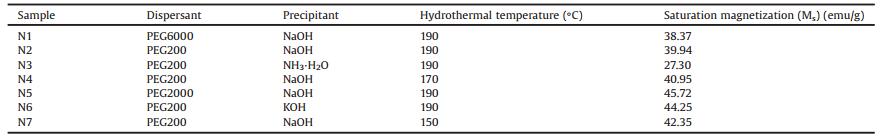
Table 1 The synthesis conditions and the saturation magnetizations of the different NiFe2O4 catalysts. |
|
|
Table 2 The synthetic conditions and the saturation magnetizations of the different NiFe2O4@SiO2 catalysts. |

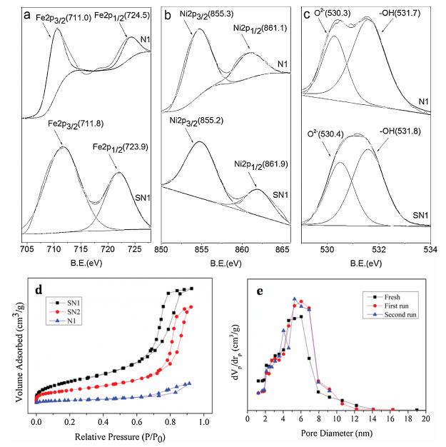
The crystal structure of NiFe2O4 and NiFe2O4@SiO2 catalysts were characterized by X-ray diffraction (XRD) using Co Kα radiation and the Fourier transform infrared spectroscopy (FTIR) spectra. Their magnetic properties were measured by vibrating sample magnetometer (VSM) with an applied field of ±10kOe at room temperature. The responding saturation magnetization (Ms) could be determined based on the obtained hysteresis loops. The surface morphologies, core-shell structure and the particle size distribution were characterized by scanning electron microscope (SEM), transmission electron microscope (TEM) and BrunnerEmmet-Teller (BET). The valent states of Fe, Ni and O were characterized by X-ray photoelectron spectroscopy (XPS). RhB degradation reaction was chosen as the probe reaction to investigate the catalytic activity of these magnetic nanoparticles catalysts. The degradation efficiency (η) was analyzed by UV spectrometer and calculated by the following formula:
|
(1) |
η: degradation efficiency; A0: initial absorbance; A: absorbance.
XRD patterns of NiFe2O4 and NiFe2O4@SiO2 catalysts are showed in Fig. 1a. The main diffraction peak of sample N1 at 2θ = 35.8° is consistent with (311) plane of NiFe2O4, the other diffraction peaks at 2θ =18.8°, 30.5°, 35.7°, 37.3°, 43.5°, 53.8°, 57.6°, 63.6°, 71.6°, 74.7° and 75.6° corresponded to the plane of (111), (220), (311), (222), (400), (422), (511), (440), (620), (533) and (622), respectively [24]. Compared to the data of spinel cubic structure (JCPDS No. 10-0325), there were no other impurity peaks appearing in XRD patterns of these NiFe2O4 catalysts except for sample N3 with the impurity peaks corresponding to α-Fe2O3. XRD patterns confirmed the formation of phase pure cubic NiFe2O4 catalysts. The existence of α-Fe2O3 was probably due to the intermediate β-FeOOH could not interactive with Ni(OH)2 in time but further dehydrated into α-Fe2O3. Itrevealed thatthe addition of ammonia as the precipitant delayed the growth rate of pH and the generation of Ni(OH)2 precipitate [25].

|
Download:
|
| Fig. 1. (a) XRD patterns of NiFe2O4 and NiFe2O4@SiO2 catalysts. (b) Hysteresis loops of the different NiFe2O4 catalysts. (c) Hysteresis loops of the different NiFe2O4@SiO2 catalysts. (d) Degradation efficiencies of RhB in 8 h over the different NiFe2O4 catalysts (reaction conditions: H2O2 = 1.25 mmol/L, NiFe2O4 = 0.5 g/L, RhB = 10 mg/L, T = 20 ℃, pH 2). (e) Degradation efficiencies of RhB in 8 h over different NiFe2O4@SiO2 catalysts under the different pH value (reaction conditions: H2O2 = 1.25 mmol/L, NiFe2O4 = 0.5 g/L, RhB = 10 mg/L, T = 20 ℃). (f) FT-IR spectrums of sample N1 and sample SN1. | |
In addition, there was a new broad peak appear at 2θ =22° in XRD patterns of NiFe2O4@SiO2 catalysts in Fig. 1a, which corresponded to the diffraction peak of SiO2. It indicated the formation of amorphous SiO2 layer over the NiFe2O4 catalysts. More interesting was, SiO2 characteristic peaks were higher with the increase of the TEOS, whereas the other peaks had not been affected, suggesting that the TEOS dosage would not affect the phase and structure of NiFe2O4@SiO2 catalysts.
The hysteresis loops of the different NiFe2O4 catalysts are shown in Fig. 1b. When the applied magnetic field reached to the maximum value of 9000Oe, sample N5 presented the highest saturation magnetization (Ms) of 45.72emu/g among three samples N1, N2, N5 using PEG as dispersant with different molecular weight (Table 1). In the same time, the samples N2 and N6, using NaOH and KOH as the precipitant, respectively, had the higher saturation magnetization than that of sample N3 by NH3·H2O. Moreover, the saturation magnetizations of samples N2, N4 andN7 synthesizedat different hydrothermal temperatures showed little increase with the decrease of hydrothermal temperatures. The catalysts can be separated from solution easily by an external magnet finally, because of the high saturation magnetization like the Fig. 1b shows.
The results of the VSM test proved that the magnification of NiFe2O4 catalysts were closely related to the molecular weight of dispersant, the basicity of precipitants and hydrothermal temperatures, indicating the highly magnetized catalysts would be obtained by using the lower molecular weight dispersant and the strong alkalis at lower temperature.
Fig. 1c shows the hysteresis loops of the different NiFe2O4@SiO2 catalysts. The saturation magnetizations of the three silica coated samples were all lower than the uncoated sample N1. Moreover, as the increase of the dosage of TEOS, the saturation magnetizations of the three NiFe2O4@SiO2 catalysts presented the sustained decrease trend (Table 2). It was very likely caused by the SiO2 layer coated over the surface of NiFe2O4 catalysts. And the larger dosage of TEOS would cause the forming of the thicker SiO2 layer, then led to the weaker magnetic and brought about the lower saturation magnetization.
Fig. 1d shows the RhB degradation efficiencies over the different NiFe2O4 catalysts. The reactions were carried out at room temperature and the initial pH value of reaction solutions is 2 [26]. The results had shown that sample N1 presented the highest degradation efficiencies of 49.78% among three samples N1, N2, N5 using PEG as dispersant with the different molecular weight. The samples N2 and N6, using NaOH and KOH as the precipitant, respectively, have the higher degradation efficiencies than sample N3 synthesized by NH3·H2O.
Fig. 1e shows the RhB degradation efficiencies over the different NiFe2O4@SiO2 catalysts. Compared to sample N1, all of the silica coated (samples SN1, SN2, SN3) catalysts presented the higher RhB degradation efficiencies. The results suggested that coated SiO2 over the surface of NiFe2O4 had enhanced the catalytic activity. The NiFe2O4 catalysts would easily gather due to the strong magnetic force. In that case, it might result in the decrease of catalytic activity. The outer SiO2 layer over the NiFe2O4 is likely to weaken the attractive force between NiFe2O4 nanoparticles and enhanced the catalytic activity. Meanwhile, the porous structure of SiO2 layer would provide more channels for the reactive species. Whereas, the RhB degradation efficiency over SN1, SN2, SN3 three samples are presented the decrease trend with the increase of TEOS dosage. It reveals that too thick SiO2 layer may lead to the increase of mass transfer resistance thus weakened the degradation activity.
The more concerning is the RhB degradation efficiency of samples SN1 and N1 increased with pH from 2 to 7. The degradation efficiency of sample SN1 rose to 72.80% at pH 7, which indicated that NiFe2O4@SiO2 catalysts have the potential as the heterogeneous Fenton-like catalyst in organic pollutant removal in neutral condition. In comparison with the relative literature reports, although its degradation efficiency is lower than that under the low pH value condition, the better catalytic activity of NiFe2O4@SiO2 catalysts in the neutral condition is beneficial to the environmental protection [27, 28].
The Fourier transformed infrared spectra of the uncoated (N1) and silica coated (SN1) nickel ferrite catalysts in Fig. 1f provide the further evidence of the interaction of coated silica and spinel nickel ferrite catalysts. In the infrared spectra of sample N1, the absorption peak at 604.67 cm-1 corresponded to the tetrahedral-metal stretching vibration, and the absorption peak at 411.68 cm-1 corresponded to the octahedron-metal stretching vibration [29]. In addition, two extra absorption peaks at 3441.65 cm-1 and 1633.75 cm-1 corresponded to the stretching vibration of H—O—H and the bending vibration of H—O—H, respectively could be observed, these two absorption peaks indicated the existence of excess H2O in NiFe2O4 sample. For sample, the absorption peaks of SN1 infrared spectra at 475.71 cm-1, 809.67 cm-1 and 1112.20 cm-1 corresponded to the bending vibration, symmetric stretching vibration and antisymmetric stretching vibration of Si-O-Si respectively. The appearance of Si—O—Si characteristic bands has proved the existence of the SiO2 layer over NiFe2O4 catalysts.
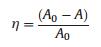
The size and morphology of the synthesized NiFe2O4 and NiFe2O4@SiO2 catalysts were characterized by SEM. Seen from Fig. 2a NiFe2O4 catalysts presented the irregular cube shape and the excellent dispersion. The size distribution of these magnetic nanoparticles was about 40~80 nm. The EDS result of NiFe2O4 in Fig. 2b indicated that there were only Fe element and Ni element existing on the surface of nanoparticles. In comparison, SEM image of NiFe2O4@SiO2 is shown in Fig. 2d. The majority of NiFe2O4@SiO2 catalysts had become near-spherical and the surface layer became smoother. The average size distribution of NiFe2O4@SiO2 increased to 50~100 nm because of the addition of SiO2 layer. In addition, the high peak of Si in Fig. 2e has further proved that NiFe2O4 had been indeed coated with SiO2 layer, which agreed well with the results of XRD, VSM and FT-IR. After coated by SiO2 layer, the nanoparticles had become smoother (Figs. 2c and f), NiFe2O4@SiO2 catalysts presented the core-shell structure.

|
Download:
|
| Fig. 2. (a) SEM, (b) EDS, (c) TEM of sample N1 and (d) SEM, (e) EDS, (f) TEM of sample SN1. | |
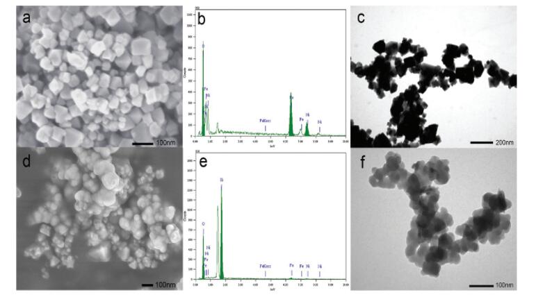
The chemical states of metal elements in the NiFe2O4 and NiFe2O4@SiO2 catalysts were studied by XPS analysis and their responding XPS characteristic spectrum are shown in Figs. 3a–c. In comparison, the binding energies of Fe 2p, Ni 2p and O 1s of SN1 were almost no change, which reveals that the SiO2 layer did not affect the valent states of Fe, Ni and O. The survey spectra of N1 and SN1 confirm that besides Fe, Ni and O were also present in these two samples. The results agree well with the explanation of XRD results. High resolution XPS spectrum of Fe 2p in Fig. 3a located at the binding energies of 711.0 eV and 724.5 eV were indicative of Fe 2p3/2 and Fe 2p1/2 of the oxidation state Fe3+ in N1, respectively. The peaks in the Ni 2p spectra (Fig. 3b) were indicative of Ni 2p3/2 and Ni2p1/2 of Ni2+ and Ni3+, located at the binding energies of 855.3 eV and 861.1 eV in N1, respectively. Most of Ni was mainly existed in +2 valent state as the peak area of Ni 2p3/2 was bigger than that of Ni 2p1/2. The peak at 530.3 eV (Fig. 3c) in N1 was due to O 1s bonded to Fe and Ni, whereas the peak at higher binding energy of 531.7 eV was ascribed to the presence of OH group [30], indicating surface contamination by hydroxides from the atmosphere.

|
Download:
|
| Fig. 3. (a) XPS spectra of Fe 2p. (b) XPS spectra of Ni 2p. (c) XPS spectra of O 1s of sample N1 and sample SN1. (d) Nitrogen adsorption-desorption isotherms of NiFe2O4 and NiFe2O4@SiO2 catalysts (N1, SN1 and SN2) (e) recyclability of NiFe2O4@SiO2 (SN1) with experimental runs of 3 successive cycles (reaction conditions: H2O2 = 1.25 mmol/L, NiFe2O4 = 0.5 g/L, RhB = 10 mg/L, T = 20 ℃, pH 7). | |
Nitrogen adsorption-desorption isotherms were measured to determine the specific surface area and pore structure of the NiFe2O4 and NiFe2O4@SiO2 catalysts, as shown in Fig. 3d. The adsorption-desorption curves of SN1, SN2 and N1 show type IV isotherms (IUPAC classification), representing their mesoporous structure, which is in accordance with the characteristic result of TEM image. The adsorption-desorption isotherm of the NiFe2O4 (N1), however, is rather different from those of NiFe2O4@SiO2 catalysts (SN1 and SN2) with a much lower adsorbing quantity. Generally, the large surface area and well-developed porosity of the hybrid catalyst are conducive to concentration of contaminates during Fenton-like catalysis as a result to enhance the catalytic performance.
At the same time, the catalytic stability of the NiFe2O4@SiO2 (SN1) was evaluated through recycle tests at the optimized reaction conditions. After each reaction, the NiFe2O4@SiO2 (SN1) was separated from suspension by magnetic separation with a permanent magnet, and then the separated NiFe2O4@SiO2 (SN1) was washed with deionized water and dried to constant weight. The recycle results are shown in Fig. 3e. It can be clearly seen that the pore structure of the NiFe2O4@SiO2 catalyst (SN1) does not change significantly after 3 cycles, which indicates the catalysts particle is extremely stable and has the potential of repeated use.
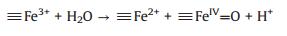
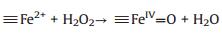
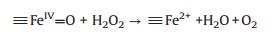
Based on the XPS analysis, the valence state of Fe in NiFe2O4@SiO2 catalysts were +3, no Fe2+ existed. It easier to infer that the possible oxidation mechanism of NiFe2O4@SiO2 catalysts may involve a high valence of iron species (≡FeIV=O) under the neutral conditions. Heterogeneous Fenton-like catalytic reactions were taken place on the catalysts surface to generate ≡FeIV=O and ≡Fe2+ active species (Eq. (2)), and then, much more ≡FeIV=O species were regenerated via the reactions between ≡Fe2+ and H2O2 (Eq. (3)), in addition, ≡FeIV=O species can react with H2O2 to generate ≡Fe2+ (Eq. (4)). The adsorbed RhB on the catalysts was oxidized mainly by ≡FeIV= O [31-33] species.
|
(2) |
|
(3) |
|
(4) |
In order to investigate the role of hydroxyl radical in the heterogeneous Fenton-like oxidation degradation of RhB over NiFe2O4@SiO2 catalysts, ethyl alcohol and tertiary butanol were selected as the excellent hydroxyl radical trapping agent, they can react with the ·OH rapidly and then ·OH trapping can be achieved [34, 35]. The initial degradation rate of RhB decreased only slightly with the addition of ethyl alcohol and tertiary butanol (Fig. S2 in Supporting information). These results verifies a high valence of iron species play a major role rather than ·OH in the oxidation degradation of RhB.
The effect H2O2 concentrations on the degradation of RhB were discussed. H2O2 concentration increased from 1.25 mmol/L to 98 mmol/L, which means H2O2 concentration increases for dozens of times. However, there was little change in degradation efficiency of RhB (Fig. S3 in Supporting information). These results further proved that the main active center may be ≡FeIV=O under the neutral conditions not ·OH in the oxidation degradation of RhB.
Generally, based on the experimental results, the as-prepared NiFe2O4@SiO2 shows the good catalytic performance, stability and reusability. Therefore, it is a promising candidate as efficient catalyst for organic wastewater treatment via Fenton-like process in practical.
In summary, NiFe2O4 and NiFe2O4@SiO2 as the heterogeneous Fenton-like catalyst were synthesized by hydrothermal method and micro emulsion method, respectively. The size of NiFe2O4 was about 40–80 nm and the size of NiFe2O4@SiO2 was about 50–100 nm. Most of NiFe2O4 samples presented the excellent crystal phase and the strong magnetic force. The catalysts having the higher magnetic force could be obtained by using the lower molecular weight dispersant and strong alkalis at lower temperature. The saturation magnetization of NiFe2O4@SiO2 catalysts was lower than NiFe2O4 catalysts because of the existence of SiO2 layer. The results of RhB degradation test indicated that the degradation efficiency of RhB over NiFe2O4@SiO2 was higher than that of NiFe2O4. The highest degradation efficiency had reached to 72.80% in the neutral condition. The existence of SiO2 layer enhanced the catalytic activity of NiFe2O4 indeed and NiFe2O4@SiO2 catalysts showed the better catalytic activity in the neutral environment than in the acidic environment.The characterization of FT-IR, SEMandTEMprovedthe existence of SiO2 layer over NiFe2O4.The XPS analysis suggested that the valent states of Fe and Ni were mainly present in +3 and +2 respectively and SiO2 did not affect the valent states of Fe, Ni and O.
AcknowledgmentThe authors acknowledge the financial support from the Fundamental Research Funds for the Central Universities (No. xjj2016045), China.
Appendix A. Supplementary dataSupplementary material related to this article can be found, in the online version, at doi:https://doi.org/10.1016/j.cclet.2019.01.021.
| [1] |
M.I. Badawy, R.A. Wahaab, A.S. El-Kalliny, J. Hazard. Mater. 167 (2009) 567-574. DOI:10.1016/j.jhazmat.2009.01.023 |
| [2] |
D. Prato-Garcia, G. Buitrón, J. Photochem. Photobiol. A 223 (2011) 103-110. DOI:10.1016/j.jphotochem.2011.08.005 |
| [3] |
S. Yahiat, F. Fourcade, S. Brosillon, A. Amrane, Desalination 281 (2011) 61-67. DOI:10.1016/j.desal.2011.07.042 |
| [4] |
A. Ziylan, N.H. Ince, Chem. Eng. J. 220 (2013) 151-160. DOI:10.1016/j.cej.2012.12.071 |
| [5] |
S. Jagadevan, N.J. Graham, I.P. Thompson, J. Hazard. Mater. 244- 245 (2013) 394-402. |
| [6] |
P. Yongrui, Z. Zheng, M. Bao, et al., Chem. Eng. J. 273 (2015) 1-6. DOI:10.1016/j.cej.2015.01.034 |
| [7] |
R. Sharma, V. Kumar, S. Bansal, S. Singhal, J. Mol. Catal. A-Chem. 402 (2015) 53-63. DOI:10.1016/j.molcata.2015.03.009 |
| [8] |
F. Duarte, F.J. Maldonado-Hódar, A.F. Pérez-Cadenas, L.M. Madeira, Appl. Catal. B 85 (2009) 139-147. DOI:10.1016/j.apcatb.2008.07.006 |
| [9] |
S. Rahim Pouran, A.R. Abdul Aziz, W.M.A. Wan Daud, Z. Embong, Appl. Surf. Sci. 351 (2015) 175-187. DOI:10.1016/j.apsusc.2015.05.131 |
| [10] |
B. Qiu, Q. Li, B. Shen, M. Xing, J. Zhang, Appl. Catal. B 183 (2016) 216-223. DOI:10.1016/j.apcatb.2015.10.053 |
| [11] |
S.B. Hammouda, N. Adhoum, L. Monser, J. Hazard. Mater. 294 (2015) 128-136. DOI:10.1016/j.jhazmat.2015.03.068 |
| [12] |
Y. Ling, M. Long, P. Hu, Y. Chen, J. Huang, J. Hazard. Mater. 264 (2014) 195-202. DOI:10.1016/j.jhazmat.2013.11.008 |
| [13] |
T. Jiang, Y.-d. Liang, Y.-j. He, Q. Wang, J. Environ. Chem. Eng. 3 (2015) 1740-1751. DOI:10.1016/j.jece.2015.06.020 |
| [14] |
T. Şener, E. Kayhan, M. Sevim, Ö. Metin, J. Power Sources 288 (2015) 36-41. DOI:10.1016/j.jpowsour.2015.04.120 |
| [15] |
J. An, L. Zhu, Y. Zhang, H. Tang, J. Environ. Sci. 25 (2013) 1213-1225. DOI:10.1016/S1001-0742(12)60172-7 |
| [16] |
K. Rusevova, R. Köferstein, M. Rosell, et al., Chem. Eng. J. 239 (2014) 322-331. DOI:10.1016/j.cej.2013.11.025 |
| [17] |
S.M. Masoudpanah, S.M. Mirkazemi, S. Shabani, P.T. Dolat Abadi, Ceram. Int. 41 (2015) 9642-9646. DOI:10.1016/j.ceramint.2015.04.029 |
| [18] |
Y. Segura, F. Martínez, J.A. Melero, J.L.G. Fierro, Chem. Eng. J. 269 (2015) 298-305. DOI:10.1016/j.cej.2015.01.102 |
| [19] |
L.M. Rossi, N.J.S. Costa, F.P. Silva, R. Wojcieszak, Green Chem. 16 (2014) 2906-2933. DOI:10.1039/c4gc00164h |
| [20] |
K.S.A. Kumar, R.N. Bhowmik, S.H. Mahmood, J. Magn. Magn. Mater. 406 (2016) 60-71. DOI:10.1016/j.jmmm.2015.12.100 |
| [21] |
A.S. Albuquerque, M.V.C. Tolentino, J.D. Ardisson, et al., Ceram. Int. 38 (2012) 2225-2231. DOI:10.1016/j.ceramint.2011.10.071 |
| [22] |
H. Wang, J. Huang, L. Ding, D. Li, Y. Han, Appl. Surf. Sci. 257 (2011) 7107-7112. DOI:10.1016/j.apsusc.2011.03.063 |
| [23] |
M.F. Taleb, Carbohydr. Polym. 114 (2014) 65-72. DOI:10.1016/j.carbpol.2014.07.061 |
| [24] |
S. Vivekanandhan, M. Venkateswarlu, D. Carnahan, et al., Ceram. Int. 39 (2013) 4105-4111. DOI:10.1016/j.ceramint.2012.10.265 |
| [25] |
H. Li, H.Z. Wu, G.X. Xiao, Powder Technol. 198 (2010) 157-166. DOI:10.1016/j.powtec.2009.11.005 |
| [26] |
Q.H. Lu, Y.J. Li, F.D. Song, H. Chen, S.T. Qi, Chem. Ind. Eng. Prog. 37 (2018) 3021-3028. |
| [27] |
J. Deng, Y.J. Chen, Y. Lu, et al., Environ. Sci. Pollut. Res. 23 (2017) 14396-14408. |
| [28] |
X.F. Wang, Y. Pan, Z.R. Zhu, J.L. Wu, Chemosphere 117 (2014) 638-643. DOI:10.1016/j.chemosphere.2014.09.055 |
| [29] |
S.Q. Liu, L.R. Feng, N. Xu, Z.G. Chen, X.M. Wang, Chem. Eng. J. 203 (2012) 432-439. DOI:10.1016/j.cej.2012.07.071 |
| [30] |
I.M. Ismail, B. Abdallah, M. Abou-Kharroub, O. Mrad, Nucl. Instrum. Methods Phys. Res. Sect. B 271 (2012) 102-106. DOI:10.1016/j.nimb.2011.11.010 |
| [31] |
W. Luo, L.H. Zhu, N. Wang, et al., Environ. Sci. Technol. 44 (2010) 1786-1791. DOI:10.1021/es903390g |
| [32] |
C.R. Keenan, D.L. Sedlak, Environ. Sci. Technol. 42 (2008) 1262-1267. DOI:10.1021/es7025664 |
| [33] |
C.H. Lee, D.L. Sedlak, Environ. Sci. Technol. 42 (2008) 8528-8533. DOI:10.1021/es801947h |
| [34] |
S.J. Hug, O. Leupin, Environ. Sci. Technol. 37 (2003) 2734-2742. DOI:10.1021/es026208x |
| [35] |
I.A. Katsoyiannis, T. Ruettimann, S.J. Hug, Environ. Sci. Technol. 42 (2008) 7424-7430. DOI:10.1021/es800649p |