 2019, Vol. 30


With the popularization of portable electronic devices, the demand for energy storage devices was increasing gradually. More and more researchers were committed to find cleaning, high efficiency, low energy consumption, sustainable and high-performance energy storage devices [1-3]. Compared with traditional energy storage devices with small capacity and short charge/ discharge performance, supercapacitors had long cycle life, reversible and fast charging/discharging performance, good charge propagation dynamics [4-7]. Supercapacitors featured both high power density and energy density to make up the gap of the battery and traditional dual battery [8]. So far, supercapacitors had already become important energy storage devices and were widely applied to all aspects of life [9, 10].
Supercapacitors were generally divided into electronic double layer capacitor and pseudo capacitor which was based on the reversible redox of capacitor electrode materials to generate the pseudo capacitance for energy storage [11, 12]. As one of conductive polymers (polyaniline (PANI) [13-15], polypyrrole [16, 17], etc.), PANI was widely used as pseudo capacitor electrode materials because of its convenient and rapid synthesis, high redox activity and good environmental stability [18, 19]. PANI could be quickly store high-density charges, resulting in high pseudo capacitance. During the charging/discharging process of the electrode, the continuous expansion and contraction of PANI would cause its structure to aggregate and collapse easily, affecting its cycle performance and life [20-22].
In order to achieve a better electrochemical performance, researchers usually combined carbon materials with PANI to construct nanocomposites. For example, PANI based carbon nanofiber composites had a specific capacitance of 601 F/g at the current densityof1 A/g [23].PANI/grahene oxide (GO) nanocomposites had a capacitance of 727 F/g at a current density of 1 A/g [24]. Among various composite materials, graphene or reduced graphene oxides (rGO)-based PANI nanocomposites always showed higher specific capacitance and larger energy density because the disadvantages of PANI were effectively overcome and the graphene provided large specific surface area, high electric double layer capacitance, wide potential window and good electrical conductivity [25, 26].However, the graphene or rGO-based PANI nanocomposites were flexible and easily stacked when it was properly pressed, which would reduce its capacitance performance [27, 28].
In order to solve the above problems, in this work, the rGO was supported on the ultralight and elastic three-dimensional (3D) porous melamine foam (MF)-derived macroporous carbon (3DPMFDMC). The 3DPMFDMC was characterized by high porosity, large specific surface area, light weight and good cycle performance [29, 30]. The rGO was dispersed into the network of 3DPMFDMC, which could acts as a support for the 3D frame. The combination greatly improved the electrical conductivity of the 3DPMFDMC/rGO, and effectively avoided the accumulation of rGObased PANI nanocomposites in the next steps. In addition, in order to strengthen the interaction between rGO and PANI, PANI was polymerized on 3DPMFDMC/rGO by in situ chemical oxidative polymerization to form 3DPMFDMC/rGO/ PANI, which improved the poor stability and electrical conductivity of PANI in the electrochemical test greatly. So, 3DPMFDMC/rGO/PANI showed higher good capacitance and cycle performance. The ultralight and elastic supercapacitors might have potential application for future energy storage devices.
In a typical experiment, GO was prepared according to the modified Hummer's method [31]. GO was confirmed by atomic force microscopy (Fig. S1 in Supporting information). The asprepared GO was prepared to different concentration (1.0 mg/mL and 2.0 mg/mL) with the ultra-pure water. The melamine foam (MF) was soaked in the GO solution for different time (12 h and 36 h) under stirring and then dried at 50 ℃. The procedure to prepare 3DPMFDMC/rGO involved two carbonization steps under N2 atmosphere. The temperature was raised to 300 ℃, kept for 30 min, and then further raised to 1000 ℃, kept for 30 min. Herein, the GO was converted to rGO, and 3DPMFDMC/ rGO was obtained. 3DPMFDMC/rGO were immersed into 5.0 mL H2SO4 (0.1 mol/L) containing 0.01 mol/L aniline. Another 5.0 mL H2SO4 containing ammonium persulfate (APS, 3 mg) was mixed with the above solution. The polymerization was carried out under an ice-water bath for different time (3 h, 6 h, 9 h and 12 h). Then 3DPMFDMC/ rGO/PANI nanocomposites were obtained after drying. The PANI and 3DPMFDMC/PANI materials were obtained according to this method. 3DPMFDMC/rGO/PANI was prepared to 10 mg/mL solution with ultra pure water. The solution (9 mL) were dipped onto the GCE, and dried in room temperature. After that, 1 mL 0.05% nafion were dipped onto the electrode and dried.
MF is a commercial foam material and has been extensively used in various fields [32]. As shown in SEM images (Fig. S2 in Supporting information), MF exhibited a 3D macroporous structure with the pore diameter of about 50 mm and these macropores connected each other via the internal skeletons. After the calcination, the MF was transformed into 3DPMFDMC. Figs. 1A and B showed that the macropores of 3DPMFDMC were kept well. As the carbonization temperature was as high as 1000 ℃, some skeletons were broken, resulting in poor electrical conductivity of 3DPMFDMC (Table S1 in Supporting information). Although the skeletons were broken, the length of skeletons was still several tens micrometers. Accordingly, the 3DPMFDMC was good supporting matrix to load rGO. The skeletons became thinner as compared with that of MF owing to the shrinkage in the carbonization.

|
Download:
|
| Fig. 1. SEM images of 3DPMFDMC (A, B), 3DPMFDMC/rGO2mg/mL-12h (C, D) and 3DPMFDMC/rGO2mg/mL-12h/PANI (E, F): Low magnification (A, C, E) and high magnification (B, D, F). (G) Optical image of a piece of 3DPMFDMC/rGO/PANI. (H) Flos albiziae supported 3DPMFDMC/rGO/ PANI without being weighed down. | |
After the rGO was loaded, the macropores of 3DPMFDMC were covered by a large number of rGO, and some broken skeletons were connected with each other via the rGO (Figs. 1C and D). The electrical conductivity of 3DPMFDMC/rGO was improved greatly as compared with that of 3DPMFDMC (Table S1). Raman spectra (Fig. S3A in Supporting information) clearly indicated the disorder degree of 3DPMFDMC/rGO was stronger than that of silicon wafer (SW)/rGO. RGO did not stack into bulks in 3DPMFDMC but was well supported by skeletons to form 3DPMFDMC/rGO foam, which would enhance their use efficiency. With the increasing of the concentration of rGO and the increase of soaking time (Fig. S4 in Supporting information), more and more rGO were loaded in 3DPMFDMC. The 3DPMFDMC did be a good supporting matrix for rGO.
Fig. 1E showed the SEM images of 3DPMFDMC/rGO/PANI. The skeleton structure of 3DPMFDMC/rGO was not changed in acid solution and rGO was still supported in 3DPMFDMC, indicating the 3DPMFDMC/rGO was very stable. Good stability might originate from the chemical bond between rGO and 3DPMFDMC [33]. Some oxygen-containing groups on rGO surface could be removed out at high temperature and connected with 3DPMFDMC and accordingly the rGO was firmly grown on the 3DPMFDMC. The exposed carbon skeleton became rough as compared with that of 3DPMFDMC/rGO, indicating PANI was also grown on the exposed carbon skeletons. The higher magnification SEM image (Fig. 1F) showed that the PANI was uniformly arrayed on 3DPMFDMC/rGO to form 3DPMFDMC/ rGO/PANI, which was similar with PANI array structures reported before [33].
As shown in Fig. 1G, the final material could be easily bent and recovered to its original shape without being damaged. Its excellent elasticity made it more versatile than other carbon materials in practical applications. The filaments of Flos albiziae were soft and slender. Fig. 1H showed that the filaments of Flos albiziae could support the target 3DPMFDMC/rGO/PANI without being weighed down. These optical images visually represented great elasticity and light-weight of 3DPMFDMC/ rGO/PANI.
Fig. S3B (Supporting information) showed the peak shape and peak position of 3DPMFDMC and 3DPMFDMC/rGO had no obvious difference, but the intensity ratio of D band and G band of 3DPMFDMC/rGO was stronger than that of 3DPMFDMC owing to the disordered assembly of rGO. Several new peaks belonged to PANI were observed in Raman spectrum. TEM images (Fig. S5 in Supporting information) also clearly displayed the presence of PANI. EDS spectra (Fig. S6 in Supporting information) showed the sharp increase in N element due to the loading of PANI. As shown in Figs. S7A and B (Supporting information), XPS results of 3DPMFDMC proved the existence of four typical N species, consistent with the results reported [34]. Figs. S7C and D (Supporting information) indicated the typical imine N (=N-), the benzenoid amine (-NH-) and the protonated nitrogen (-N+-) in 3DPMFDMC/rGO/PANI. The results further indicated the growth of PANI in 3DPMFDMC/ rGO. FTIR spectrum of 3DPMFDMC/rGO (curve b, Fig. S8 in Supporting information) was consistent with that of 3DPMFDMC (curve a, Fig. S8). As for 3DPMFDMC/rGO/PANI (curve b, Fig. S8), the peaks at 1610 cm-1, 1470 cm-1, 1380 cm-1 and 1170 cm-1 appeared, consistent with that of PANI (curve c, Fig. S8), also demonstrating 3DPMFDMC/rGO/ PANI was formed.
EIS was used to study charge transfer and ion diffusion process of nanocomposites. In Fig. S9A (Supporting information), 3DPMFDMC showed the poor electrical conductivity owing to the broken skeletons. The assembly of rGO with good electrical conductivity improved the electrical conductivity of 3DPMFDMC/rGO greatly. But the assembly of rGO in skeleton and pores would inhibit the ion transfer. CVs were used to further explore the best time for PANI growth (Fig. S10 in Supporting information). After 12 h (curve d, Fig. S10), the redox peaks of PANI arrived at the maximum value. Based on the above results, MF was determined to be soaked in the rGO solution for 12 h in the optimal concentration of 2.0 mg/mL. The comparison of CVs of various nanocomposites (Fig. S11 in Supporting information) could further confirm the successful growth of rGO and PANI. CVs of 3DPMFDMC/rGO2mg/mL-12h/PANI showed the maximum peak current, indicating it was the best nanocomposite.
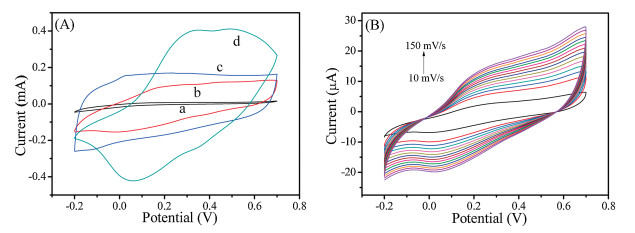
CVs in Fig. 2A observed the capacitance of 3DPMFDMC was small enough to be ignored. The capacitance of 3DPMFDMC/ rGO2mg/mL-12h was obviously enhanced, indicating that the assembled rGO did be benefit for the capacitance of supercapacitors. It was noted that the capacitance of the 3DPMFDMC/ PANI was not as large as 3DPMFDMC/ rGO2mg/mL-12h/PANI and close to that of 3DPMFDMC/rGO2mg/mL-12h, indicating the 3DPMFDMC/ rGO2mg/mL-12h could enhance the capacitance of the nanocomposites. Fig. 2B was CVs of 3DPMFDMC/rGO2mg/mL-12h/PANI under different scan rates, the cathode peak current and anode current increased with the increasement of the scan rate and the peak remained constant, showing a good rate capability.

|
Download:
|
| Fig. 2. (A) CVs of 3DPMFDMC (a), 3DPMFDMC/PANI (b), 3DPMFDMC/rGO2mg/mL-12h (c), 3DPMFDMC/rGO2mg/mL-12h/PANI (d) electrodes in 0.1 mol/L H2SO4 at 50 mV/s. (B) CVs of 3DPMFDMC/rGO2mg/mL-12h/PANI electrode in 0.1 mol/L H2SO4 solution at different scan rate by step of 10 mV/s. | |
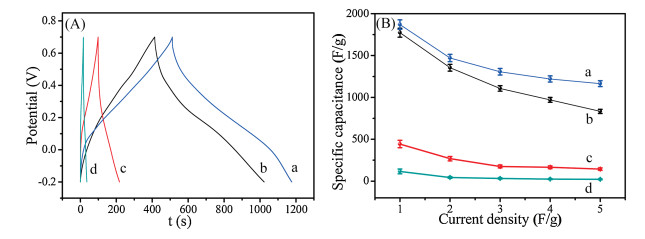
Fig. 3A compared the galvanostatic charging/discharging curves of3DPMFDMC/rGO2mg/mL-12h/PANI(1471.1 F/g, curvea), 3DPMFDMC/ rGO1mg/mL-12h/PANI (1354 F/g, curve b), 3DPMFDMC/rGO1mg/mL-36h/ PANI(268 F/g, curvec)and3DPMFDMC/rGO2mg/mL-36h/PANI(43.3 F/g, curved).The results clearly showed 3DPMFDMC/rGO2mg/mL-12h/PANI had the best electrochemical performance (Fig. 3B and Fig. S12 in Supporting information). Such good performance might originate from the effective use of rGO toload alarge number of PANI.Although lots of works had reported the growth of PANI on rGO, the service efficiency of PANI/rGO was not so high due to the stacking of PANI/rGO on electrode surface (Table S2 in Supporting information). The 3DPMFDMC was a good supporting matrix to load rGO into 3D rGO foam. The elastic 3DPMFDMC/rGO foam could effectively hinder the stacking of nanocomposites, which enhanced the service efficiency of active PANI greatly. Furthermore, the porous carbon foam could improve the electron/ion transfer.

|
Download:
|
| Fig. 3. (A) Charging/discharging curves of 3DPMFDMC/rGO2mg/mL-12h/PANI (a), 3DPMFDMC/rGO1mg/mL-12h/PANI (b), 3DPMFDMC/rGO1mg/mL-36h/PANI (c) and 3DPMFDMC/ rGO2mg/mL-36h/PANI (d) in 0.1 mol/L H2SO4 solution at current density of 2 A/g. (B) Specific capacitance plots of the above nanomaterials. | |
The cycling stability test (Fig. 4) of 3DPMFDMC/rGO2mg/mL-12h/ PANI showed the specific capacitance slightly decreased in the first four hundred laps, probably through a series of PANI activation by H2SO4. After 4000 cycles, the specific capacitance gradually stabilized and remained at 1111.1 F/g. The results signified 3DPMFDMC/rGO2mg/mL-12h/PANI had good cycling stability. The long cycling life might result from their hierarchical configuration and chemical bond between rGO and 3DPMFDMC. Such 3D porous configuration effectively avoid the contact of active materials each other in the charging/ discharging process. And the chemical bond between rGO and 3DPMFDMC prevented the active materials from dropping off electrode surface in the charging/discharging process. Therefore, the cycling stability was improved greatly, which was obviously superior to some nanocomposites.

|
Download:
|
| Fig. 4. Cycling performances of 3DPMFDMC/rGO2mg/mL-12h/PANI in 0.1 mol/L H2SO4 solution at current density of 5 A/g. Inset:Constant current charging/discharging profiles of 3DPMFDMC2mg/mL-12h/PANI in 0.1 mol/L H2SO4 solution at various current densities. | |
In summary, we successfully developed the ultralight and elastic 3DPMFDMC/rGO/PANI as supercapacitor electrode materials for the first time. The uniform distribution of rGO connected the broken fibers of 3DPMFDMC produced in the high temperature carbonization to improve the electrical conductivity greatly and enlarge the specific surface area of nanocomposites. The 3DPMFDMC could be used as good supporting matrix for the assembly of rGO to avoid the stacking, which greatly improved the use efficiency of rGO. The PANI was vertically arrayed on 3DPMFDMC/rGO to form 3DPMFDMC/rGO/PANI exhibiting a rapid electron/mass transport. Owing to their hierarchical configuration and good properties, the 3DPMFDMC/rGO/PANI nanocomposites showed great specific capacitance of 1870 F/g at 1 A/g and a good cycle performance having a 95% specific capacitance after cycling for 5000 cycle at the current density of 5 A/g.
AcknowledgmentsThis work was financially supported by the National Natural Science Foundation of China (Nos. 21465014 and 21465015), and the Ground Plan of Science and Technology Projects of Jiangxi Educational Committee (No. KJLD14023).
Appendix A. Supplementary dataSupplementary material related to this article can befound, in the online version, at doi:https://doi.org/10.1016/j.cclet.2019.02.007.
| [1] |
S. Guo, D. Wen, E. Wang, et al., ACS Nano 4 (2010) 3959-3968. DOI:10.1021/nn100852h |
| [2] |
C. Gong, S. Sun, G. Wei, et al., Nanoscale 11 (2019) 147-4182. |
| [3] |
K. Li, G. Wei, Z. Su, et al., Adv. Funct. Mater. 28 (2018) 1801056. DOI:10.1002/adfm.v28.29 |
| [4] |
C. Tang, Z. Pu, Y. He, et al., ChemElectroChem 2 (2015) 1903-1907. DOI:10.1002/celc.201500285 |
| [5] |
P. Zhang, Z. Su, F. Wang, et al., NPG Asia Mater. 10 (2018) 429-440. DOI:10.1038/s41427-018-0049-y |
| [6] |
L. Kang, S.X. Sun, Y.C. Luo, et al., Chin. Chem. Lett. 25 (2014) 957-961. DOI:10.1016/j.cclet.2014.05.032 |
| [7] |
Y. Han, Q. Zhang, H. Wei, et al., Chin. Chem. Lett. 28 (2017) 2269-2273. DOI:10.1016/j.cclet.2017.10.024 |
| [8] |
Y. Cheng, H. Zhang, J. Liu, et al., Nanoscale 5 (2013) 1067-1073. DOI:10.1039/C2NR33136E |
| [9] |
B. Hu, X. Qin, X. Sun, et al., Electrochim. Acta 100 (2013) 24-28. DOI:10.1016/j.electacta.2013.03.133 |
| [10] |
Y. Huang, M. Zhu, C. Zhi, et al., J. Mater. Chem. A 4 (2016) 1290-1297. DOI:10.1039/C5TA09473A |
| [11] |
Y. He, X. Xiao, Y. Shen, et al., ChemElectroChem 4 (2017) 607-612. DOI:10.1002/celc.v4.3 |
| [12] |
Z. Xing, Q. Chu, X. Sun, et al., J. Power Sources 245 (2014) 463-467. DOI:10.1016/j.jpowsour.2013.07.012 |
| [13] |
H.Y. Chen, J. Wang, K. Jiao, et al., Chin. Chem. Lett. 27 (2016) 231-234. DOI:10.1016/j.cclet.2015.09.018 |
| [14] |
X.Q. Li, W.W. Liu, M.Q. Ge, et al., Chin. Chem. Lett. 25 (2014) 83-86. DOI:10.1016/j.cclet.2013.10.003 |
| [15] |
R. Oraon, De Adhikari A., G.C. Nayak, et al., ACS Sustain. Chem. Eng. 4 (2016) 1392-1403. DOI:10.1021/acssuschemeng.5b01389 |
| [16] |
Y. He, Y. Bai, Z.H. Liu, et al., J. Power Sources 317 (2016) 10-18. DOI:10.1016/j.jpowsour.2016.03.089 |
| [17] |
Q. Niu, Y. Guo, K. Gao, Z. Shao, RSC Adv. 6 (2016) 109143-109149. DOI:10.1039/C6RA23216G |
| [18] |
J.J. Cai, L.B. Kong, J. Zhang, Y.C. Luo, L. Kang, Chin. Chem. Lett. 21 (2010) 1509-1512. DOI:10.1016/j.cclet.2010.07.003 |
| [19] |
A. Eftekhari, L. Li, Y. Yang, J. Power Sources 347 (2016) 86-107. |
| [20] |
X. Ning, W. Zhong, L. Wan, RSC Adv. 6 (2016) 25519-25524. DOI:10.1039/C6RA00596A |
| [21] |
M. Wang, Y.X. Xu, Chin. Chem. Lett. 27 (2016) 1437-1444. DOI:10.1016/j.cclet.2016.06.048 |
| [22] |
C. Hu, S. He, S. Jiang, S. Chen, H. Hou, RSC Adv. 5 (2015) 14441-14447. DOI:10.1039/C4RA12220H |
| [23] |
Y.E. Miao, W. Fan, D. Chen, T. Liu, ACS Appl. Mater. Inter. 5 (2013) 4423-4428. DOI:10.1021/am4008352 |
| [24] |
A.G. Tabrizi, N. Arsalani, H. Namazi, et al., Electrochim. Acta 265 (2018) 379-390. DOI:10.1016/j.electacta.2018.01.166 |
| [25] |
Q. Wang, L. Jiao, H. Du, Y. Wang, H. Yuan, J. Power Sources 245 (2014) 101-106. DOI:10.1016/j.jpowsour.2013.06.035 |
| [26] |
H.P. Cong, J.F. Chen, S.H. Yu, Chem. Soc. Rev. 43 (2014) 7295-7325. DOI:10.1039/C4CS00181H |
| [27] |
L. Wang, X. Lu, S. Lei, Y. Song, J. Mater. Chem. A 2 (2014) 4491-4509. DOI:10.1039/C3TA13462H |
| [28] |
Q. Wu, Y. Xu, Z. Yao, A. Liu, G. Shi, ACS Nano 4 (2010) 1963-1970. DOI:10.1021/nn1000035 |
| [29] |
S.Z. Chen, F. Xie, K.Q. Chen, et al., Carbon 111 (2017) 867-877. DOI:10.1016/j.carbon.2016.10.085 |
| [30] |
X. Zhong, Z. Yang, Y. Yu, et al., ACS Appl. Mater. Inter. 8 (2016) 32360-32365. DOI:10.1021/acsami.6b11873 |
| [31] |
Hummers Jr W.S., R.E. Offeman, J. Am. Chem. Soc. 80 (1958) 1339-1339. DOI:10.1021/ja01539a017 |
| [32] |
M. Inagaki, J. Qiu, Q. Guo, Carbon 87 (2015) 128-152. DOI:10.1016/j.carbon.2015.02.021 |
| [33] |
L. Wang, L. Miao, H. Yang, L. Xu, C. Peng, Electrochim. Acta 281 (2018) 638-645. DOI:10.1016/j.electacta.2018.06.008 |
| [34] |
H. Zhang, Y. Zhou, H. Hou, et al., Carbon 95 (2015) 388-395. DOI:10.1016/j.carbon.2015.08.025 |