 2019, Vol. 30


An increasing demand for energy storage devices drives the development of research on low-cost, environmentally friendly and high-performance electrochemical energy storage materials. Supercapacitors, featured by high power density, safety and long cycle lifetime, have been investigated extensively to meet the need in many practical applications including electronics, vehicles and grids [1, 2]. Depending on the charge storage mechanism, supercapacitors can be classified into two types, namely, the electrical double layer capacitor (EDLC) and the pseudo-capacitor. In contrast to EDLCs, pseudo-capacitor material including conducting polymers like polypyrrole (PPy) [3-5] and polyaniline (PANI) [6-9], various transition metal oxides such as MnO2 [10-13], RuO2 [14, 15], as well as battery-type materials like NiO [16, 17], Nb2O5 [18], Co2O3 [19, 20] and CuO [21, 22], ZnO [23, 24], SnO [25, 26], possess outstanding capacity of high energy storage. In general, poor electrical conductively property and low specific surface area are the shortcomings for most transitional metal based electrode materials for capacitive applications [27-29]. More recently, metal sulfides have attracted much attention owing to their potential applications in catalysis [30], optics, solar energy [31], sensing, and batteries [32, 33]. They are also suitable candidates for supercapacitors (SCs) due to their higher electrochemical activity and conductivity than corresponding metal oxides [34-37]. A variety of metal sulfides such as CuS [38, 39], ZnS [40, 41], SnS [42, 43] and MoS [44] have been studied as potential electrochemical energy storage materials. In addition, mixed metal sulfides, especially ternary nickel cobalt sulfides, exhibiting great potential to improve the electrochemical performance of supercapacitor owing to their richer redox activity compared with corresponding single metal sulfides [27]. Most notably, copper, zinc, tin sulfides have demonstrated much higher conductivity and electrochemical activity than the corresponding copper, zinc, tin oxides due to their smaller band gaps [34], respectively. Simultaneously, some studies reported that CuxSnyS(x+y) as the electrode materials exhibited the mediocre performance because of the poor electrical conductivity compared with other metal sulfides [45]. However, by adding zinc into copper tin sulfide (CuxSnyS(x+y)/ZnS), the electrical conductivity was significantly enhanced with improved electrochemical performance. Recently, CuxZnySnzS(x+y+z) (CZTS), as a promising sulfide for next generation photovoltaic devices, has been widely studied for its advantage of earth-abundant, nontoxic and low-cost sources [46]. It is also suitable for large-scale production, which will alleviate energy storage.
In this work, we synthesized flower-like Cu5Sn2S7/ZnS nanocomposite as electrode materials for supercapacitors. The electrochemical performance of the nanocomposite was compared with pristine Cu5Sn2S7. The result showed that the ZnS improved electrochemical performance of Cu5Sn2S7 significantly. A high specific capacitance of Cu5Sn2S7/ZnS up to 200 F/g was obtained at current density of 1 A/g. It is worth mentioning that even at high current density of 10 A/g, the specific capacitance of Cu5Sn2S7/ZnS still remained at 170 F/g. The outstanding cycling stability, and rate capability and stable capacitance retention, making it a promising electrode material for high performance supercapacitors.
All the chemicals used in the work were provided by Sigma Aldrich and used as received unless otherwise stated. Ethylene alcohol, copper(Ⅱ) chloride dehydrate (CuCl2·2H2O), zinc(Ⅱ) chloride (ZnCl2), tin(Ⅳ) chloride tetrahydrate (SnCl4·4H2O) and sodium chloride (NaCl) were all of analytical grade. Thiourea (CH4N2S) and Polyvinylpyrrolidone (PVP) were the products of Alfa. All water used was obtained from a Milli-Q purification water system with a resistivity of 18.2 M Ω cm.
In a typical experimental procedure, 2 mmol copper(Ⅱ) chloride dihydrate, 1 mmol zinc(Ⅱ) chloride, 1 mmol tin(Ⅳ) chloride tetrahydrate, 5 mmol thiourea and 0.64 g PVP were dissolved in 40 mL ethylene glycol under magnetic stirring. Then the mixture was loaded into a Teflon-lined stainless steel autoclave of 50 mL capacity. The sealed autoclave was maintained at 230 ℃ for 24 h. After this, it was allowed to cool to room temperature. The precipitate was centrifuged and washed with deionized water and ethanol several times to remove by-products. The final product was vacuum-dried at 60 ℃ before characterization.
Cu5Sn2S7/ZnS nanocomposite was used as the precursor, which was treated with 0.2 mol/L NaCl aqueous solution with soaking time of 10 min under ultrasonication [47]. The precipitate was centrifuged and washed with deionized water and ethanol several times to remove by-products. The final product was vacuum-dried at 60 ℃ before characterization.
The morphology of the samples was probed by field emission scanning electron microscopy (FESEM, JSM-7001F, JEOL) equipped with energy dispersive X-ray spectroscopy (EDS) using an accelerating voltage of 20 kV. The crystal structure of the samples was examined by X-ray diffraction system (XRD, PAnaytical MPD Cu power XRD) equipped with Cu Ka radiation. The diffraction data were recorded in the range of 2θ angle from 10° to 80°. The surface elemental compositions of the materials were measured using X-ray photoelectron spectroscopy (XPS, Kratos AXIS Supra photoelectron spectrometer) with an Al X-ray as excitation source.
The electrochemical measurements, such as the cyclic voltammetry (CV), galvanstatic charge-discharge (GCD), and electrochemical impedance spectroscopy (EIS) were carried out with the synthesized materials using an electrochemical workstation with a three electrode system in 6 mol/L KOH electrolyte at room temperature. A platinum electrode was used as the counter electrode, a saturated calomel electrode (SCE) as reference electrode, and Cu5Sn2S7/ZnS or Cu5Sn2S7 as working electrode. The working electrode was fabricated by pressing the mixture of the Cu5Sn2S7/ZnS (Cu5Sn2S7) nanocomposite, acetylene black (conductive agent) and poly(terafluoroethylene) (PTFE) binder with a weight ratio of 8:1:1 in ethanol on to a nickel foam substrate. The mass loads of the active electrode material was 5 mg. The CV curves were collected in a potential window from 0 to 0.5 V at different scan rates ranging from 1 mV/s to 50 mV/s. The GCD tests were conducted at different current densities in a potential range from 0 V to 0.5 V. The EIS measurements were recorded at an open-circuit potential with frequency range from 105 Hz to 10-2 Hz under a signal amplitude of 5 mV. The electrochemical test with the three-electrode system was performed without particular removal of oxygen in the solution. The specific capacitance was calculated from GCD curves using Eq. (1):
|
(1) |
where I (mA) is the applied working current, Δt (s) represents the discharge time, ΔV (V) is the voltage range, and m (mg) is the total mass of active materials in both electrodes.
The electrochemical measurements of the assembled asymmetric supercapacitor device, which used the Cu5Sn2S7/ZnS or Cu5Sn2S7 as the positive electrode, porous carbon as the negative electrode in a two-electrode system with 6 mol/L KOH as electrolyte were also performed. The energy density and power density were calculations were based on positive and negative electrodes and did not include the mass of the electrolyte.
To study the crystallographic structure of the flower-like Cu5Sn2S7/ZnS, we further measured the XRD of the materials. Fig. 1a shows the resultant XRD diffraction patterns of Cu5Sn2S7/ ZnS composite and Cu5Sn2S7 material. The XRD diffraction peaks of the Cu5Sn2S7 mainly located at 2θ = 28.6°, 47.5°, 56.5° corresponding to (111), (220) and (311) planes, which can be indexed to the corresponding PDF standard card of Cu5Sn2S7 (JCPDS 40-0924). It indicated that the sample were constituted only Cu5Sn2S7 phase [48]. As can be seen, three more diffraction peaks of Cu5Sn2S7/ZnS appear than that of the pristine material. The diffraction peaks located at 33.3°, 56.5° and 66.7° corresponding to (0010), (110) and (118) planes of ZnS (JCPDS No. 12-0688).

|
Download:
|
| Fig. 1. (a) X-ray diffraction pattern and (b) Raman spectra of the as-obtained Cu5Sn2S7/ZnS and pristine Cu5Sn2S7. | |
The Raman spectra of the flower-like Cu5Sn2S7/ZnS composite and pristine Cu5Sn2S7 are shown in Fig. 1b. The peaks of pristine Cu5Sn2S7 are found at 332 cm-1 and 296 cm-1, corresponding to the literature [48] which detailed the Raman peaks of Cu5Sn2S7. For Cu5Sn2S7/ZnS composite, two more Raman spectrum peaks appear than that of the pristine material. The Raman spectrum peaks (at 278 and 351 cm-1) than that for the pristine materials (Cu5Sn2S7) were recognized, indicating the existence of ZnS [49]. No other characteristic peaks corresponding to Cu2ZnSnS4 (CZTS) (288, 336 and 372 cm-1) observed, which confirmed no existence of CZTS in the sample.
The morphological features of the synthesized Cu5Sn2S7/ZnS were firstly observed by using SEM, as shown in Fig. 2 both the low-magnification and high-magnification SEM images show that the sample is composed of flower-like nanoparticles with good uniformity. The enlarged SEM image, shown in Fig. 2d, reveals that the flower-like structure is constructed with dozens of 2D nanosheets with size approximately 100 nm. These nanosheets were connected to each other through the center to form 3D hierarchical structure. This unique structure provides an abundant porous surface sites for the contact between the electrode and the electrolyte, which is of great significance for facilitating electrochemical reactions. Compared with Cu5Sn2S7/ZnS, the morphology of pristine Cu5Sn2S7 was investigated by SEM as well (Fig S1 in Supporting information). Clearly after removing ZnS, the flower-like morphology was completely destroyed when treated by NaCl solution.

|
Download:
|
| Fig. 2. SEM images of the Cu5Sn2S7/ZnS nanocomposite with different magnifications. | |
Further investigation of elemental composition and valence state of the Cu5Sn2S7/ZnS were carried out by XPS. The full survey spectrum shown in Fig. S2 (Supporting information) demonstrates that the Cu5Sn2S7/ZnS is composed of Cu, Zn, Sn, S, C and O. It is observed in Fig. 3a that the Cu binding energy peaks located at 932.3 eV (2p3/2) and 952.5 eV (2p1/2). The typical Zn 2p peaks appears at 1022.1 eV (2p3/2) and 1045.1 eV (2p1/2), with a peak splitting of 23.0 eV indicating Zn (Ⅱ) configuration (Fig. 3b). The Sn 3d5/2 and 3d3/2 peaks are located at 486.9 and 495.4 eV, with a peak splitting of 8.5 eV, indicating Sn (Ⅳ) configuration (Fig. 3c). The S 2p core-level spectrum in Fig. 3d shows two peaks located at 162.3 eV (2p3/2) and 163.3 eV (2p1/2) with the peak separation of 1 eV, which are consistent with the 160–164 eV range of S in the sulfide phases. These results are in consistent with previous reports [49].

|
Download:
|
| Fig. 3. XPS spectra of Cu5Sn2S7/ZnS composite: Cu 2p region (a); Zn 2p region (b); Sn 3d region (c) and S 2p region (d). | |
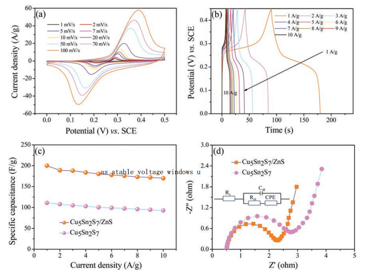
The electrochemical performance of the Cu5Sn2S7/ZnS nanocomposite was measured by cyclic voltammetry (CV) and galvanostatic charging-discharging (GCD) testing. The CV of Cu5Sn2S7/ZnS electrode at a series of scan rate (1–100 mV/s) can be seen in Fig. 4a. All the curves are featured with a pair of welldefined redox peaks, indicating the battery-type energy storage of the material features. Furthermore, the pair of remarkable reversible redox peaks at different scan rates, indicates that the electrochemical capacitance mainly came from Faradic redox reaction rather than the electric double layer capacitors. The anodic peak is consistent with the conversion of Cu+ to Cu2+ and Sn2+ to Sn4+, and cathodic peak is its reversible process. The corresponding Faradic reaction is described by the following equations:
|
(2) |
|
(3) |

|
Download:
|
| Fig. 4. (a) Cyclic voltammograms (CV) of Cu5Sn2S7/ZnS electrode at different scan rates; (b) Galvanostatic charging-discharging of Cu5Sn2S7/ZnS electrode at different current densities; (c) specific capacitance of Cu5Sn2S7/ZnS and Cu5Sn2S7 electrode at different current densities and (d) Nyquist plots of Cu5Sn2S7/ZnS and Cu5Sn2S7 electrode. | |
When the potential scan rate increases, the peak current becomes larger, whereas the oxidation and reduction peaks of the CV curve does not change obviously. This shows excellent kinetics for electrochemical reaction of material.
Galvanostatic charging-discharging plots of the Cu5Sn2S7/ZnS nanocomposite are shown in the Fig. 4b. The present of a platform at ~0.25 V indicates the unique battery-type energy storage characteristics, and it is consistent with the redox peaks observed in Fig. 4a. The specific capacitance calculated by Eq. (1) at the different charging-discharging current density (1–10 A/g) is shown in Fig. 4c. The GCD curves are approximately symmetric, suggesting the good electrochemical capacitive characteristic of the Cu5Sn2S7/ZnS. The Cu5Sn2S7/ZnS delivered capacitance of 200.2, 189.1, 188.3, 184.6, 180.5, 178.0, 175.8, 175.3, 172, 170.1 F/g at the current densities of 1, 2, 3, 4, 5, 6, 7, 8, 9 and 10 A/g, respectively. The CVs and GCDs curves of Cu5Sn2S7 are shown in Fig. S3 (Supporting information). The specific capacitance of the pristine Cu5Sn2S7 are 111.1, 108, 105, 103.2, 100.5, 99.0 97.5, 96.0, 94.5 and 93 F/g at the current density of 1, 2, 3, 4, 5, 6, 7, 8, 9 and 10 A/g, respectively. At each current densities, the specific capacitance of Cu5Sn2S7/ZnS nanocomposite is higher than that of pristine Cu5Sn2S7 electrode. The results suggest that the ZnS could play a key role in enhancing the electrochemical performance of the material due to the synergistic effect between Cu5Sn2S7 and ZnS. In general, the specific capacitance of each material decreases with an increasing current density. This phenomenon can be attributed to the presence of the inner active sites, which could not sustain the redox transitions completely under a higher current density. Impressively, about 84.9% of the capacitance was retained for Cu5Sn2S7/ZnS nanocomposite at current densities from 1 A/g to 10 A/g. This result suggests that the charge could be effectively transferred from one to the other species inside the nanocomposite Cu5Sn2S7/ZnS. Thus, the decoration of Cu5Sn2S7 with ZnS could enhance the electrochemical performance of the pristine Cu5Sn2S7 electrode materials for practical applications.
The electrochemical properties of the material such as internal resistance, electrons transfer resistance and capacity of supercapacitors were analyzed by EIS. The Nyquist plots of the Cu5Sn2S7/ ZnS and Cu5Sn2S7 are shown in Fig. 4d, the equivalent circuit of the Cu5Sn2S7/ZnS and Cu5Sn2S7 electrode is inset in Fig. 4d. The X-intercept of the Nyquist plots corresponds to the equivalent series resistance (Rs) and the high frequency region presenting a semicircle arc is a result of the charge transfer resistance (Rct). Obviously, although the Cu5Sn2S7/ZnS has the same Rs (0.5 Ω) with Cu5Sn2S7. The Rct for the Cu5Sn2S7/ZnS (1.7 Ω) is lower than that of Cu5Sn2S7 (2.2 Ω). The semicircle with a diameter corresponds to Rct at the high frequency region is caused by Faradic reactions at interfaces of electrode and electrolyte [50]. In addition, from the vertical diffusion lines we can see that the Cu5Sn2S7/ZnS shows a steeper slope than the Cu5Sn2S7 suggesting a better reaction rate. These results indicate more efficient interfacial charge transfer of the Cu5Sn2S7/ZnS than that of Cu5Sn2S7, consistent with the higher electrochemical performance of the former.
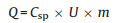
To further investigate the electrochemical properties of the Cu5Sn2S7/ZnS and Cu5Sn2S7 nanocomposite in practical applications, the asymmetric supercapacitors composed of PC/KOH/ Cu5Sn2S7/ZnS and PC/KOH/Cu5Sn2S7 was assembled using PC (porous carbon) as the negative electrode and Cu5Sn2S7/ZnS or Cu5Sn2S7 as the positive electrode in a 2 mol/L KOH aqueous electrolyte solution. Before the fabrication of the asymmetric supercapacitors, optimization of the electrode mass loadings was carried out to achieve balanced energy storage capacity. As shown in Eq. (4), the charge stored by each electrode usually depends on the specific capacitance (Csp), the potential range (U) and the mass of active materials (m) [51]:
|
(4) |
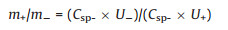
In order to obtain Q+ = Q-, the mass balancing is expressed as Eq. (5):
|
(5) |
where Q is the capacity and subscripts represent positive and negative electrode.
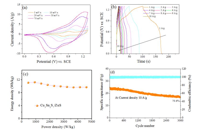
The performance of the asymmetric supercapacitor of PC/KOH/ Cu5Sn2S7/ZnS is shown in Fig. 5. Fig. 5a shows the asymmetric supercapacitor has stable voltage windows up to 1.3 V. Similar to the CVs of the three electrode cell, the CV curve of the asymmetric supercapacitor of PC/KOH/Cu5Sn2S7/ZnS exhibits psedo-capacitive behavior with a pair of redox peaks at different scan rates, indicating the fast charge transport and stable electrochemical capacitive characteristics of the supercapacitor. Fig. 5b shows the galvanoststic charge-discharge measurements of the asymmetric supercapacitor. It is observed with an approximately symmetrical slope shape in GCD curve, suggesting the good reversibility and good rate capability of the supercapacitor. The Ragone plot in Fig. 5c shows the energy density of PC/KOH/Cu5Sn2S7/ZnS supercapacitor reaches 11.2 Wh/kg at power density of 923.1 W/kg, and even at high power density of 4516.4 W/kg the energy density still remains at 9.68 Wh/kg. Fig. 5d shows the long-term cycle stability of the supercapacitor of PC/KOH/Cu5Sn2S7/ZnS, which was tested by GCD measurement repeating 3000 cycles at current density of 10 A/g. It is noticed that the retention rate of specific capacitance showed outstanding stability, after 3000 cycles, the device shows the retention rate of 70.6% compare with the initial value.

|
Download:
|
| Fig. 5. (a) Cyclic voltammograms (CV) of PC/KOH/Cu5Sn2S7/ZnS supercapacitor at different scan rates; (b) Galvanostatic charging-discharging of PC/KOH/Cu5Sn2S7/ZnS supercapacitor at different current densities; (c) Ragone plot of PC/KOH/Cu5Sn2S7/ZnS supercapacitor; (d) Cycling behavior of PC/KOH/Cu5Sn2S7/ZnS supercapacitor at current density 10 A/g. | |
In summary, a flower-like Cu5Sn2S7/ZnS nanocomposite was synthesized by the one-step hydrothermal method. The electrochemical performance of the Cu5Sn2S7/ZnS was compared with the pristine Cu5Sn2S7. Due to the synergistic effect between Cu5Sn2S7 and ZnS, the resultant Cu5Sn2S7/ZnS nanocomposite showed the enhanced electrochemical performance compared with pristine ZnS. Cu5Sn2S7/ZnS nanocomposite delivered the specific capacitance of 200 F/g at current density of 1 A/g and maintained 170 F/g at current density of 10 A/g in 6 mol/L KOH solution. An asymmetric supercapacitor was assemble based on PC/KOH/ Cu5Sn2S7/ZnS and delivered a desirable energy density of 11.08 Wh/kg with power density of 461 W/kg. At the same time, 70.6% of initial capacitance still remained after 3000 charge-discharge full process at current density of 10 A/g. This work offers a simple way to synthesise flower-like Cu5Sn2S7/ZnS nanocomposite, used in supercapacitor with a superior electrochemical performance.
AcknowledgmentsF. Yu thanks the support via Postgraduate Research Award of Queensland University of Technology (QUTPRA). The date were obtained at the Central Analytical Research Facility (CARF) operated by the institute for Future Environments, QUT. Access to CARF is supported by generous funding from the Science and Engineering Faculty (QUT).
Appendix A. Supplementary dataSupplementary material related to this article canbefound, in the online version, at doi:https://doi.org/10.1016/j.cclet.2019.01.004.
| [1] |
F.X. Wang, X.W. Wu, X.H. Yuan, et al., Chem. Soc. Rev. 46 (2017) 6816-6854. DOI:10.1039/C7CS00205J |
| [2] |
F. Yu, T. Wang, Z.B. Wen, H.X. Wang, J. Power Sources 364 (2017) 9-15. DOI:10.1016/j.jpowsour.2017.08.013 |
| [3] |
X. Jian, H.M. Yang, J.G. Li, E.H. Zhang, Z.H. Liang, Electrochim. Acta 228 (2017) 483-493. DOI:10.1016/j.electacta.2017.01.082 |
| [4] |
Z.M. Fan, J.P. Zhu, X.H. Sun, et al., ACS Appl. Mater. Interfaces 26 (2017) 21763-21772. DOI:10.1021/nn1006368 |
| [5] |
Q. Meng, K. Cai, Y. Chen, L. Chen, Nano Energy 36 (2017) 268-285. DOI:10.1016/j.nanoen.2017.04.040 |
| [6] |
A. Eftekhari, L. Li, Y. Yang, J. Power Sources 347 (2017) 86-107. DOI:10.1016/j.jpowsour.2017.02.054 |
| [7] |
K. Zhou, Y. He, Q. Xu, et al., ACS Nano 12 (2018) 5888-5894. DOI:10.1021/acsnano.8b02055 |
| [8] |
Z.Y. Liu, S.H. Liu, R. Dong, et al., Small 14 (2017) 1603388. |
| [9] |
H. Li, J. Song, L. Wang, et al., Nanoscale 1 (2017) 193-200. |
| [10] |
S. Zhu, L. Li, J. Liu, et al., ACS Nano 2 (2018) 1033-1042. |
| [11] |
Z. Fan, J. Yan, T. Wei, et al., Adv. Funct. Mater. 12 (2011) 2366-2375. DOI:10.1016/j.carbon.2017.08.006 |
| [12] |
Q. Qu, P. Zhang, B. Wang, et al., J. Phys. Chem. C 31 (2009) 14020-14027. DOI:10.1007/s10904-017-0564-2 |
| [13] |
L. Peng, X. Peng, B. Liu, et al., Nano Lett. 5 (2013) 2151-2157. |
| [14] |
C.C. Hu, K.H. Chang, M.C. Lin, Y.T. Wu, Nano Lett. 12 (2006) 2690-2695. |
| [15] |
Q. Jiang, N. Kurra, M. Alhabeb, Y. Gogotsi, H.N. Alshareef, Adv. Energy Mater. 13 (2018) 1703043. |
| [16] |
F. Yu, L. Zhu, T. You, F. Wang, Z. Wen, RSC Adv. 116 (2015) 96165-96169. |
| [17] |
Y. Zeng, L. Wang, Z. Wang, J. Xiao, H. Wang, Mater. Today Commun. 5 (2015) 70-74. DOI:10.1016/j.mtcomm.2015.11.001 |
| [18] |
J. Liao, R. Tan, Z. Kuang, et al., Chin. Chem. Lett. 29 (2018) 1785-1790. DOI:10.1016/j.cclet.2018.11.018 |
| [19] |
N. Kandasamy, T. Venugopal, K. Kannan, J. Nanosci. Nanotechn. 6 (2018) 3960-3968. |
| [20] |
X. Wang, M. Li, Z. Chang, et al., ACS Appl. Mater. Inter. 4 (2015) 2280-2285. |
| [21] |
Z. Li, M. Shao, L. Zhou, et al., Nano Energy 20 (2016) 294-304. DOI:10.1016/j.nanoen.2015.12.030 |
| [22] |
Y. Liu, X. Cao, D. Jiang, D. Jia, J. Liu, J. Mater. Chem. A 22 (2018) 10474-10483. |
| [23] |
C.H. Kim, B.H. Kim, J. Power Sources 274 (2015) 512-520. DOI:10.1016/j.jpowsour.2014.10.126 |
| [24] |
F. Yu, L. Zhou, T. You, et al., Mater. Lett. 194 (2017) 185-188. DOI:10.1016/j.matlet.2017.02.050 |
| [25] |
Y. Zhang, Z. Hu, Y. Liang, et al., J. Mater. Chem. A 29 (2015) 15057-15067. |
| [26] |
S. Tan, J. Li, L. Zhou, et al., J. Mater. Sci. 16 (2018) 11648-11658. |
| [27] |
H. Yuan, L. Kong, T. Li, Q. Zhang, Chin. Chem. Lett. 28 (2017) 2180-2194. DOI:10.1016/j.cclet.2017.11.038 |
| [28] |
Y. Li, J. Chen, Y. Ji, et al., J. Energy Chem. 27 (2018) 463-471. DOI:10.1016/j.jechem.2017.11.016 |
| [29] |
T. Wang, H.C. Chen, F. Yu, X.S. Zhao, H. Wang, Energy Storage Mater. 16 (2019) 545-573. DOI:10.1016/j.ensm.2018.09.007 |
| [30] |
J. Wang, N. Yu, Y. Zhang, et al., J. Alloys. Compd. 688 (2016) 923-932. DOI:10.1016/j.jallcom.2016.07.012 |
| [31] |
X. Lin, J. Kavalakkatt, A. Ennaoui, M.C. Lux-Steiner, Sol. Energy Mater. Sol. Cells 132 (2015) 221-229. DOI:10.1016/j.solmat.2014.08.024 |
| [32] |
C. Zhang, Y. Jiao, T. He, et al., Phys. Chem. Chem. Phys. 38 (2017) 25886-25890. |
| [33] |
J. Lin, J. Guo, C. Liu, H. Guo, ACS Appl. Mater. Interfaces 50 (2016) 34372-34378. |
| [34] |
C. Wang, H. Tian, J. Jiang, et al., ACS Appl. Mater. Interfaces 31 (2017) 26038-26044. |
| [35] |
J. Mei, T. Liao, Z. Sun, J. Energy Chem. 27 (2017) 117-127. |
| [36] |
W. Kong, C. Lu, W. Zhang, J. Pu, Z. Wang, J. Mater. Chem. A 23 (2015) 12452-12460. |
| [37] |
X.Y. Yu, Y. Feng, Y. Jeon, et al., Adv. Mater. 40 (2016) 9006-9011. |
| [38] |
X. Li, K. Zhou, J. Zhou, J. Shen, M. Ye, J. Mater. Sci. Tech. 34 (2018) 2342-2349. DOI:10.1016/j.jmst.2018.06.013 |
| [39] |
J. Guo, X. Zhang, Y. Sun, et al., J. Power Sources 355 (2017) 31-35. DOI:10.1016/j.jpowsour.2017.04.052 |
| [40] |
X. Hou, T. Peng, J. Cheng, et al., Nano Res. 8 (2017) 2570-2583. |
| [41] |
Y. Sui, Y. Zhang, H. Hu, et al., Adv. Mater. Interfaces 5 (2018) 1800018. DOI:10.1002/admi.v5.12 |
| [42] |
C. Liu, S. Zhao, Y. Lu, et al., Small 12 (2017) 1603494. |
| [43] |
S. Ravuri, C.A. Pandey, R. Ramchandran, S.K. Jeon, A.N. Grace, Int. J. Nanosci. 2 (2018) 1760022. |
| [44] |
J. Liang, Z. Wei, C. Wang, J. Ma, Electrochim. Acta 285 (2018) 301-308. DOI:10.1016/j.electacta.2018.07.230 |
| [45] |
J. Lin, J. Guo, C. Liu, H. Guo, ACS Appl. Mater. Interfaces 31 (2015) 17311-17317. |
| [46] |
S. Zhang, H.D. Hadi, Y. Wang, et al., IEEE J. Photovol. 8 (2018) 856-863. DOI:10.1109/JPHOTOV.2018.2813264 |
| [47] |
V.T. Tiong, T. Hreid, S. Zhang, J. Bell, H. Wang, Thin Solid Films 615 (2016) 305-310. DOI:10.1016/j.tsf.2016.07.045 |
| [48] |
Z.H. Su, K. Sun, Z. Han, et al., J. Mater. Chem. 22 (2012) 16346-16352. DOI:10.1039/c2jm31669b |
| [49] |
V.T. Tiong, J. Bell, H. Wang, Beilstein J. Nanotech. 5 (2014) 438-446. DOI:10.3762/bjnano.5.51 |
| [50] |
Z.B. Wen, F. Yu, T. You, et al., Mater. Res. Bull. 74 (2016) 241-247. DOI:10.1016/j.materresbull.2015.10.035 |
| [51] |
F. Yu, Z. Chang, X. Yuan, et al., J. Mater. Chem. A 14 (2018) 5856-5861. |