 2019, Vol. 30


In the information age, microwave communication, due to its high frequency and stable transmission, had already been widely applied in our life. However, with the rapidly development of the electronic information industry, devices for the high-frequency and high speed application request the further improvement of reliability and excellent dielectric properties. Therefore, to achieve real applications of the novel materials for microwave communication, the low dielectric loss, low thermal expansion coefficient (CTE) and machinability are requested. Dielectric ceramics, such as CaO-Li2O-Sm2O3-TiO2 (CLST), meet these requirements with their low dielectric loss, low CTE. However, their brittleness makes them fault for mechanical processing, which limits the application in real microwave communication [1].
As we know, the polymers have excellent machinability due to its natural property. Combining the advantages of ceramics and polymers, the composites of ceramic and polymer are rapid developed in the past years [2-4]. Among these polymers, polytetrafluoroethylene (PTFE) has caused concern of the industry and academia, due to its excellent dielectric properties such as low permittivity, extremely low loss tangent [1, 5-7]. However, the application of PTFE was hindered by its high CTE (~400 ppm/℃) due to its room temperature phase transformation [8]. To improve the mechanical stability, glass fibers (GF) was used as a reinforcing phase due to its low CTE (~0.5 ppm/℃), high modulus, high toughness and light weight in PTFE-based composite [9]. And the influence of GF filled microwave dielectric composites has been also studied. Z. Li et al. [10] have reported effects of surface modified GF on the properties of PTFE/glass fiber microwave composites. The PTFE with surface modified GF composite shows improved density (2.174 g/cm3), dielectric constant (2.18), and decreased dielectric loss (0.0009), moisture absorption (0.008%) and temperature coefficient of dielectric constant (-18.6 ppm/℃). F. Luo et al. [11] reported a series of microwave materials of NST/GF filled PTFE, which exhibits the good dielectric properties of dielectric constant (εr = 4.95), low dielectric loss (tanδ = 0.00147), acceptable water absorption (0.036) and temperature coefficient of dielectric constant (τε = -164 ppm/℃).
In the above-mentioned work, the researchers mainly focused on the property of GF-reduced CTE. Unfortunately, these improvements of mechanical stability are usually companied with a sacrifice of dielectric properties. The dielectric loss may increase significantly because of the inhomogeneous structure of the GF reinforced composites. The inhomogeneous dispersion of GF is caused by the poor interface compatibility, which is originated from GF's surface hydrophily and polymer's surface hydrophobicity. Therefore, GF is preferred to be modified by coupling agent to improve interface compatibility and GF' dispersion in the composites [12, 13].
In our previous work, notably dielectric properties of the high dielectric constant and low dielectric loss at high frequency were achieved in the CLST/PTFE composite [14]. In this paper, to improve the dimensional stability furtherly, GF was introduced into the composites. And the titanate coupling agent LD125 was employed to modify GF' surface and improve their dispersion. The CLST/PTFE/ GF composites were successfully prepared, and the effects of modified GF for the CTE and dielectric properties were investigated. The low dielectric loss, low CTE and machine-ability CLST/PTFE/ GF composite was obtained, which is the promising material for microwave communication.
The CLST ceramic powder was synthesized by a simply solidstate method [14]. The PTFE powder was purchased from Chenguang Research Institute of Chemical Industry (China). The GF was provided by Nanjing Fiberglass Research Design Institute of China. The GF was prepared by the centrifugal spin spun method and treated by H2SO4 before modified. Titanate coupling agent LD125 was supplied by the Lida resin Co., Ltd.
Before fabricating the GF reinforced CLST/PTFE composites, the CLST ceramic and the GF were both modified by titanate coupling agent LD125. GF: 1.5 wt% amount of LD125 was dissolved in the ethanol solution; after stirring 15 min, the GF washed by H2SO4 was added and magnetic stirred 1 h; finally, the obtained mixture was dried at 80 ℃ and crushed. CLST: 1 wt% amount of LD125 was dissolved in the ethanol solution with acetic acid; then, after stirring after 15 min, the CLST powders was added and magnetic stirs 1 h; finally, the mixture was dried at 80 ℃ for overnight and 150 ℃ for 2 h.
Different amount (0 wt%, 1 wt%, 3 wt%, 5 wt%, 7 wt% and 10 wt%) of modified GF and 40 VF% CLST/PTFE powder were mixed by crushing mixer, respectively. Then, the mixtures were pressed by static press and hot press at 405 ℃ for 2 h, respectively. The samples are named CLST/PTFE/x%GF (x = 1–10).
The morphology of the glass fibers and CLST/PTFE/x%GF samples are characterized by scanning electron microscopy (SEM) (JEOL, JSM-5610LV, Japan). The phase of samples is detected by X-ray powder diffraction (XRD) (Philips, X'Pert Pro MPD, Netherlands). The dielectric constant and dielectric loss of the CLST/PTFE/GF samples are measured by Agilent HP8722ET network analyzer using the strip-line resonance method. These dielectric properties are tested at the resonant frequency of ~10 GHz, the middle point of the X band (8–12 GHz). The CTE was tested according to the standard of IPC-TM-650. Before testing, the samples were immersed in isopropyl alcohol and mixed 20 s, then dried at 110 ℃ for 1 h and cooled to room temperature.
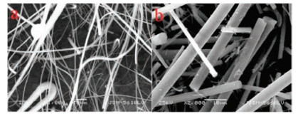
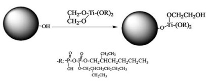
Fig. 1 shows the SEM images of the GF before and after modified. Before modification, there are long fibers and lots of spherical glass slag. It could be found that the modified GF is smooth and there is no glass slag. The diameter of GF is ~1–5 μm. The reaction progress is shown in Scheme 1. In the LD125, it concludes the P=O bond, which suggested that PTFE form a chelated structure with the phosphate groups. Therefore, the composite can form a stable structure. After modified by LD125, the –CH2OH group will be obtained, which. By H2SO4 treatment, the –OH group is grafted on the surface of GF, and then the groups react with LD125 to graft -CH2OH group on the surface, which can tightly link with PTFE.

|
Download:
|
| Fig. 1. SEM images of glass fiber (a) before and (b) after modification. | |

|
Download:
|
| Scheme 1. The process of the glass fiber modified by LD125 titanate coupling agent. | |
Fig. 2 shows the cross-sectional SEM images of CLST/PTFE composites filled with/without GF. It is observed that the CLST and PTFE compacted well. After GF filled, the tri-materials still compacted well and GF uniformly distributes in the composites. The filling amount of CLST/PTFE/1%GF is too little to be observed in Fig. 2a. We can clearly observe GF in the CLST/PTFE/3%GF, CLST /PTFE/5%GF and CLST /PTFE/7%GF samples, as shown in Figs. 2c–e. There are some round holes in the CLST/PTFE/GF samples, which were formed by GF taken-off, indicating that the GF connect very well with CLST/PTFE composite. It will overcome the increasing of the dielectric loss due to the GF introduce.

|
Download:
|
| Fig. 2. SEM images of CLST/PTFE with/without GF composites. (a) CLST/PTFE unfilled GF, (b) CLST/PTFE/1%GF, (c) CLST/PTFE/3%GF, (d) CLST/PTFE/5%GF, (e) CLST/PTFE-/7%GF. | |
Fig. 3 shows the XRD patterns of CLST/PTFE composites filled with various GF contents. The XRD patterns show the same peaks and without the new peak in CLST/PTFE/GF samples. Since the GF is amorphous and its content is less than 7 wt%, the existence of GF in the composites is not detected by XRD.

|
Download:
|
| Fig. 3. The XRD patterns of 1%–5% GF filled CLST/PTFE composites. | |
Fig. 4a shows the microwave dielectric properties of the 1– 10 wt% GF filled CLST/PTFE composites. It illustrates the dielectric constant and dielectric loss of the composites with no function of GF filling. However, all the CLST/PTFE/x%GF (x = 0–10) samples deliver the low dielectric loss, which is lower than 0.005. At the beginning, its dielectric loss slightly decreases from 0.0027 to 0.0026. Then, the dielectric loss slightly increases, even with the 7% GF filling, which dielectric loss is only about 0.0031. All the samples show the low dielectric loss, because of that both CLST/PTFE composite and GF are excellent low dielectric loss materials. Therefore, the CLST/PTFE/GF composites remain their low dielectric loss properties. The dielectric loss sharply increases for 10%GF filling CLST/PTFE sample. Because GF arrangement in the composite makes the material more ceramics, PTFE and glass fiber three-phase interface, which has inevitably some defects. However, with inorganic filler modified by coupling agent can improve the mixing uniformity between the matrixes. Because of the diameter, length and high content of GF (> 10%), it is difficult to connect well with granular PTFE together. Lots of defects would increase the dielectric loss, leading the poor dielectric properties for the composite materials. Compared with the dielectric loss, the dielectric constant variation exhibits an opposite trend. The unfilled sample delivers a dielectric constant with 8.38. Then the dielectric constant goes down with the GF loading increasing. It almost shows a linear relationship between dielectric constant and GF constant. This trend due to the small dielectric constant of GF (~3.9), which decreases the dielectric constant of the composite. The CLST/PTFE/7%GF and CLST/PTFE/10%GF exhibit the dielectric constant of 7.62 and 7.1, respectively. Therefore, to achieve the wide application in microwave communication, the dielectric constant can be tuned by filling the different content of GF in the CLST/PTFE composites.

|
Download:
|
| Fig. 4. Microwave dielectric properties: (a) Dielectric constant and (b) CTE in both X&Y and Z directions of the 1%–7% GF filled CLST/PTFE composites. | |
The CLST/PTFE/GF samples prohibit the excellent properties of dielectric loss and dielectric constant. To understand their CTE properties, including both X&Y direction and Z direction, the standard IPC-TM-650 was carried out. The results are shown in Fig. 4b. Both of X&Y-CTE and Z-CTE decrease with the GF contents increasing. The unfilled CLST/PTFE sample has same X&Y-CTE and Z-CTE of 43 ppm/℃, indicating that the spherical granular ceramics particles are isotropic distributed in the composite leading to isotropic resistance. With the GF introduce, the X&Y-CTE and Z-CTE exhibit the different change trend, indicating the different orientation of the GF. The Z-CTE decreases significantly at the beginning, which is about 37 ppm/℃ the CLST/PTFE/1%GF sample. Then Z-CTE decreases slightly to 30 ppm/℃ in the CLST/PTFE/5%GF. Finally, even when the GF loading increases to 7%, the Z-CTE keeps about 29 ppm/℃ without obvious variation. The GF loading less than 3%, the X&Y-CTE decreases from 43 ppm/℃ to 25 ppm/℃. Then, the X&Y-CTE of CLST/PTFE/4%GF and CLST/PTFE/5%GF is 24 and 20 ppm/℃. Finally, the X&Y-CTE slightly changes to 19 ppm/℃ when the GF loading increase to 7%. Both of X&Y-CTE and Z-CTE changes relative significantly before GF loading less than 5%; then they go down slowly. All in all, the CTE significantly decreases after GF introduce. Based on the dielectric loss, dielectric constant and CTE, all the samples with GF loading less than 7% can work well. However, the composite with GF loading content of 5% delivers the best combination property in all samples.
For CLST/PTFE composite, the thermal expansion mismatched during the heating or cooling processes, due to the different CTE of PTFE and CLST. In the heating process, the PTFE exhibits the increasing compressive stress while the CLST exhibits the extensive stress. It can be overcome by introducing the third phase, such as GF. In the CLST/PTFE/GF composites, the PTFE chains and GF interweave with each other, as shown in Fig. 3, leading a strong adhesion between each other. The thermal motions of PTFE molecules, which is needed overcome the resistance such as the cohesive force between structural segments on adjacent chains, and also the friction of adhesion with GF, inhibited by the thermal stability of GF. The interface carrying the transmitting stresses decreases the thermal expansion of PTFE when the composite is heated. The GF suffers more stress, which limits the CTE of PTFE. Therefore, the CTE of the CLST/PTFE/GF composites is reduced compared without GF filled sample.
Furthermore, the low Z-CTE of the composites is important for dimensional stability and mechanical compatibility mixed with other materials, which will widen its application. The CLST/PTFE/ GF composites exhibit excellent dielectric properties and low CTE, which is significantly important in the microwave communication field.
In this paper, GF with LD125 surface modification was introduced to CLST/PTFE dielectric composites. The effects of GF content on the dielectric properties and CTE of the composites were investigated. It is obvious that the dielectric constant decreases, dielectric loss increases and CTE in both X&Y direction and Z direction decreases with GF content increasing. When the content of GF is lower than 7%, its dielectric loss gently increases. The CTE significantly decreases when the content of GF is lower than 5%. Therefore, the CLST/PTFE/5%GF exhibits the best comprehensive performance. This material shows the low dielectric of 0.0029 and low CTE both in X&Y direction (20 ppm/℃) and Z direction (30 ppm/℃). The suitable GF introduced to CLST/PTFE composite can significantly improve the properties in the application of microwave communication. Therefore, the CLST/ PTFE/GF composite is a promising dielectric material for microwave communication, especially on the multilayer microwave circuit board.
AcknowledgmentsThis work was supported by the National Natural Science Foundation of China (No. 51572205), the Equipment Pre-Research Joint Fund of EDD and MOE (No. 6141A02033209), the Fundamental Research Funds for the Central Universities (WUT: Nos. 2017III035, 2018III019), and the Natural Science Foundation of Hubei Province, China (No. 2014CFB854).
| [1] |
L. Zheng, J. Zhou, J. Shen, et al., J. Mater. Sci. Mater. Electron. 29 (2018) 17195-17200. DOI:10.1007/s10854-018-9811-8 |
| [2] |
S. Vaucher, V.V. Yakovlev, H. Yeung, Polym. Eng. Sci. 58 (2018) 319-326. DOI:10.1002/pen.v58.3 |
| [3] |
J. Castro, E.A. Rojas-Nastrucci, A. Ross, T.M. Weller, J. Wang, IEEE Trans. Microw. Theory Tech. 65 (2017) 2073-2084. DOI:10.1109/TMTT.2017.2655057 |
| [4] |
C. Xie, F. Liang, M. Ma, et al., Crystals 7 (2017) 126. DOI:10.3390/cryst7050126 |
| [5] |
P.S. Anjana, M.T. Sebastian, M.N. Suma, P. Mohanan, Int. J. Appl. Ceram. Technol. 5 (2008) 325-333. DOI:10.1111/ijac.2008.5.issue-4 |
| [6] |
C. Pan, K. Kou, Q. Jia, et al., Compos. Part B-Eng. 111 (2017) 83-90. DOI:10.1016/j.compositesb.2016.11.050 |
| [7] |
Y. Qi, Q. Luo, J. Shen, et al., Appl. Surf. Sci. 414 (2017) 147-152. DOI:10.1016/j.apsusc.2017.04.072 |
| [8] |
T.S. Sasikala, M.T. Sebastian, Ceram. Int. 42 (2016) 7551-7563. DOI:10.1016/j.ceramint.2016.01.162 |
| [9] |
I.G. Lee, D.H. Kim, K.H. Jung, H.J. Kim, H.S. Kim, Compos. Struct. 177 (2017) 28-37. DOI:10.1016/j.compstruct.2017.06.007 |
| [10] |
Z. Li, J. Liu, Y. Yuan, E. Li, F. Wang, RSC Adv. 7 (2017) 22810-22817. DOI:10.1039/C7RA02715J |
| [11] |
F. Luo, B. Tang, Y. Yuan, Z. Fang, S. Zhang, Appl. Surf. Sci. 436 (2018) 900-906. DOI:10.1016/j.apsusc.2017.11.207 |
| [12] |
G. Luo, W. Li, W. Liang, et al., Compos. Part B-Eng. 111 (2017) 190-199. DOI:10.1016/j.compositesb.2016.12.016 |
| [13] |
W. Yang, Y.R. Zhang, A.C.Y. Yuen, et al., Chem. Eng. J. 321 (2017) 257-267. DOI:10.1016/j.cej.2017.03.123 |
| [14] |
L. Zheng, J. Zhou, J. Shen, et al., J. Mater. Sci. Mater. Electron. 28 (2017) 11665-11670. DOI:10.1007/s10854-017-6969-4 |