 2019, Vol. 30


b College of Chemistry and Molecular Engineering, Zhengzhou University, Zhengzhou 450001, China

Yuqin Zou received her bachelor and master's degree in 2012 from Shanghai University and her PhD in 2017 from The University of Manchester. She is currently a lecturer of the College of Chemistry and Chemical Engineering, Hunan University. Her current research interests are in novel 2D materials, such as graphene, layered double hydroxide and black phosphorus, and their applications in electrocatalysis;

Shuangyin Wang received his bachelor degree in 2006 from Zhejiang University and PhD in 2010 from Nanyang Technological University, Singapore. He was a postdoctoral fellow working with Prof. Liming Dai (2010–2011) and Prof. A. Manthiram (2011–2012). He was a Marie Curie Fellow in the University of Manchester with Prof. K. Novoselov (2012–2013). He is currently a Professor of the Key Laboratory for Graphene Materials and Devices and College of Chemistry and Chemical Engineering, Hunan University. His research interests are in plasma technology, defects in various crystals and their application for electrochemical energy storage and conversion.
Due to these environmental issues and depleting fossil fuels supplies, the research and development of renewable energy are of vital importance in the coming decades [1-3]. The electrochemical energy storage and conversion devices, including metal-air batteries, fuel cells, water splitting, and CO2 conversion devices, are of great importance to solve the emerging energy crisis [4-7]. Electrocatalysis accelerates the charge transfer process between the interface of the electrode and electrolyte and determines the performance of these electrochemical energy storage and conversion devices directly [8]. Noble metals and their derivatives were commonly used in these devices [9-11]. However, noble metal-based catalysts limited the large-scale production of this renewable energy storage and conversion devices due to the high price, poor stability, and scarcity [12-14]. Undoubtedly, to design low cost, highly active and high stability electrocatalysts with transition metals are of great importance in the field of modern electrocatalysis [15,16]. Meanwhile, the storage and conversion of new energy also require catalysts to achieve.
It can be seen that the catalyst has become the driving force for chemical process development and technological progress. However, the present state-of-the-art status of modern reactor design and catalyst preparation technology is not perfect [17]. For instance, there are some catalytic reactions, including ammonia synthesis (Haber–Bosch process), activation of carbon-hydrogen bonds and CO2 reforming of methane [18,19]. In particular, the Haber–Bosch process, which is commonly used in the ammonia synthesis industry, needs to be carried out in the presence of a catalyst under conditions of high temperature and pressure. It encourages chemists around the world to develop a new method for large-scale ammonia synthesis under mild conditions using renewable energy. To achieve this goal, some new techniques or new reactors need to be designed to help reduce raw material and energy consumption, improve equipment productivity and product quality, and prevent environmental pollution.
In response to the above questions, researchers have proposed the concept of process intensification, aiming to increase production efficiency, reduce production costs, improve safety and reduce environmental pollution [20-22]. The characteristics of the plasma green chemical process are precisely in line with the requirements of process intensification. Therefore, emerging plasma technology attracts significant interest in modifying electrocatalysts because of its unique functions and potential applications [23-25]. As a powerful tool for the preparation and modification of materials, plasma has been widely used in electrochemistry [26]. In plasma, particles which mainly in the form of high energy states, would be efficient to synthesize or modify the electrocatalysts [27]. Compared with traditional chemical synthesis methods, plasma technology has many advantages [28]. For example, plasma technology can simplify a complicated synthetic procedure and avoid the use of some toxic and hazardous chemicals. Moreover, it is a green and time-saving method for synthesizing electrocatalysts. The primary objective of the development of this green technology is (ⅰ) improving the conventional reaction process which requires high energy consumption, (ⅱ) providing the time-saving method to prepare highly dispersed, high-performance electrocatalyst or electrocatalyst supports to enhance the catalytic performance [29]. Moreover, conventional materials that do not have catalytic activity are likely to be high-efficiency catalysts under the action of plasma. It is even possible to achieve organic synthesis reactions that are difficult or impossible to reach by conventional methods, such as CO2 conversion, N2 fixation [30,31].
To date, lots of research has focused on applying plasma technology to air purification [32,33], water treatment [34], surface modification of materials [35], gas reforming [36], syntheses of metal oxides (with specific nanostructure) [37], nanoparticle synthesis [38], and so on. At the same time, researchers have gradually applied plasma technology and strategy to the preparation of electrocatalysts. There are two main strategies for synthesizing high-performance electrocatalysts, one is to create more active sites, and the other is to enhance the catalytic performance of the unit active site. For instance, these are effective means to reach these objects, such as doping heteroatoms, creating vacancies and controlled synthesis the size/structures [28,39]. Surprisingly, high-energy species in plasma can bring unexpectedly high activity to electrocatalysts. It allows researchers to apply plasma technology to modify and prepare electrocatalysts directly. It found that plasma technology has less introduction of impurities, the higher catalytic activity of the electrocatalysts, shorter reaction time, and so on, compared with traditional synthesis methods [25].
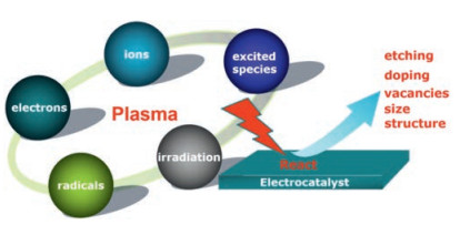
In this review, we summarized the latest applications of plasma in energy storage and conversion, including using it as the preparation and modification technology of the various electrocatalysts and the usage of it as the synthesis technology directly (Fig. 1). Firstly, we presented the definition and types of plasma reactors and their respective characteristics. Then, these applications of plasma technology in many essential electrode reactions including carbon dioxide reduction reaction (CO2RR), nitrogen fixation, oxygen reduction reaction (ORR), oxygen evolution reaction (OER) and hydrogen evolution reaction (HER) were introduced. Finally, the challenges and outlook of plasma technology in energy storage and conversion were summarized, and the solutions and prospected its development in the future were present. Through this review, to some extent, we hope it can depiction some basic skills to apply plasma technology to the synthesis (including plasma exfoliation, interface and generating new active species) and modification (including plasma etching, doping, and vacancies) of electrocatalysts. At the same time, we hope that it will give readers a broad and comprehensive understanding of the plasma action mechanism and a basic idea about operating several plasma reactors.

|
Download:
|
| Fig. 1. Applications of plasma technology in energy storage and conversion. | |
2. Plasma technology 2.1. Definition
In general, plasma is an ionized gas (also called the fourth state of matter). In plasma, these ionized gases, including ions, electrons, free radicals, and excited species, which produced by ionization exist in the form of high energy states (Fig. 2) [40]. To excite matters to high energy states, sufficient energy which mainly provided by different kinds of electricity, such as direct current (DC), low frequency (LF), radio frequency (RF) or microwave frequency (MW) were needed to be applied to various gases [41].

|
Download:
|
| Fig. 2. Plasma composition and its modification strategy for electrocatalyst. | |
2.2. Plasma types
According to their temperature and energy levels, the plasma can be divided into high-temperature plasma and low-temperature plasma (including thermal and cold plasma). High-temperature plasma is usually used in the nuclear application, while low-temperature plasma is a useful tool for the preparation and modification of materials [40].
The temperature of plasma is described as the gas bulk temperature and the electron temperature. In thermal plasma, the gas bulk temperature is similar to the electron temperature which is usually relatively high. Thus, it often demands relatively high temperatures and massive energy consumption, which hinder its use in the modification of nanomaterials [42]. On the contrary, in cold plasma, the electrons temperature can reach as high as 10,000–100,000 K (1–10 eV), while the temperature of the gas can be kept at room temperature [40]. Moreover, the cold plasma reaction is easy to implement since less equipment is needed. Therefore, the cold plasma technology has become an effective strategy for modifying organic and inorganic materials [41]. Also, some physical and chemical reactions can take place at relatively low temperatures with the help of plasma [43].
Depending on the methods of generating plasma, the cold plasma can be mainly divided into glow discharge, corona discharge, dielectric barrier discharge (DBD), radio frequency (RF) discharge, and microwave discharge [27]. Recently, a few reviews have summarized the various application of plasma reactors in energy conversion and storage [3,26,27]. However, a timely review of the vivifying plasma technology filed is also needed.
3. Plasma strategy for CO2RRThe massive consumption of fossil fuel has led to a sharp increase in greenhouse CO2 emissions, which caused increasingly environmental severe problems [44]. Conversion of CO2 into small organic molecules with improved energy density, such as CO, C2H4, formic acid, methanol, and methane, can not only reduce the accumulation of CO2 in the atmosphere but also produce fuels and value-added chemicals [45]. Particularly, electrochemical CO2 reduction using electricity generated from renewable sources, such as sunlight and wind, provides a highly desirable solution to plastic carbon recycling under mild reaction conditions, has attracted much attention [46]. Many nanomaterials were developed as electrocatalysts for CO2RR, such as Ag2S, Cu, Cu oxides, and N-doped carbons [47-53]. Among them, plasma treatment was a used tool for preparation and modification of the electrocatalysts.
Min's group studied the structure effect on the catalyst by preparing Au islands using O2 plasma treatment on an Au foil [30]. They found the Faradaic efficiency, product formation rate, and onset potentials for CO2RR were all improved by the expanded surface areas compared with the untreated Au foils. Later, Cuenya's group have demonstrated that the structure effect plays only a partial role in improving catalytic performance [51]. They prepared a series of copper-based catalysts by O2 and H2 plasma treatment, respectively. Compared with the fresh Cu foils, all plasma-treated samples had higher surface roughness while only these oxidized ones showed lower onset potentials and higher selectivity for ethylene (60%), indicating the roughness had a partial effect on improving its catalytic activity while the oxidized copper species played a crucial role in lowering the onset potential and increasing ethylene selectivity (Figs. 3A-C). The group also reported a lowpressure plasma pre-treatment on Cu nanocubes could tune Cu (100) facet and oxygen/chlorine ion content, resulting in highly active and selective Cu nanocube electrocatalysts [52]. Compared with electropolished Cu foil, plasma-assisted prepared Cu nanocubes had relatively low overpotential and higher hydrocarbon selectivity (with the Faraday Efficiency of 22% for ethanol, 45% for ethylene, and 73% for all C2 and C3 compounds) (Figs. 3D-E). After O2 plasma treatment, it can be seen that the sample with dominant Cu2+ component due to heavily oxidation, while the Auger spectra of the other samples are dominated by Cu+ species (Fig. 3E). The characterization and electrochemical measurements revealed that the activity of these electrocatalysts could be improved by tuning microstructure, ion content, defect concentration, and surface roughness. Meanwhile, the group synthesized oxidized and defective Ag electrocatalysts for CO2RR by a plasma oxidation pre-treatment [53]. The plasma treatment can increase the specific surface area of the Ag foils and enhance the number of low-coordinated active sites, which lowers the overpotential and improves the performance of the CO2 electroreduction. DFT calculation also showed that the highly defective surface of Ag foils with the presence of local electric fields can decrease the overpotential of CO2RR.

|
Download:
|
| Fig. 3. (A) C2H4 Faradaic selectivity of the CO2RR product after 60 min of electrolysis at a constant potential in CO2 saturated 0.1 mol/L KHCO3. (B) Summary of hydrocarbon selectivity of plasma-treated Cu foils. (C) Geometric reduction current density as a function of applied potential. Reproduced with permission [51]. Copyright 2016, Nature Publishing Group. (D) Geometrical current density and C2H4 Faradaic efficiency of the samples treated with different plasma treatments. (E) Cu Auger LMM XPS spectra of Cu nanocube samples, measured quasi-in situ before (left) and after (right) 1 h of CO2 electroreduction reaction at -1.0 V vs. RHE. Reproduced with permission [52]. Copyright 2017, American Chemical Society. (F) CO Faradaic efficiency of CO2RR over plasma-treated Ag foil. Reproduced with permission [53]. Copyright 2017, Wiley-VCH. | |
4. Plasma strategy for nitrogen fixation
Ammonia (NH3) is considered as an essential chemical for both agriculture fertilizer and energy carriers [54-56]. The conventional Haber-Bosh process to produce NH3 often requires high temperature, high pressure, huge fossil fuel consumption, low NH3 yield (15%), and leads to significant CO2 emission [57]. Alternatively, the synthesis of ammonia through the non-thermal plasma at low temperature and pressure has recently attracted considerable attention [31]. Plasma-assisted electrochemical nitrogen fixation uses water as a hydrogen source; the reaction can be carried out at low temperature and pressure. As early as 1989, Sugiyama first synthesized ammonia from nitrogen-hydrogen plasma using radio-frequency discharges and microwave discharge [58]. Since then, various efforts have been made into the plasma-assisted ammonia synthesis process [59-64].
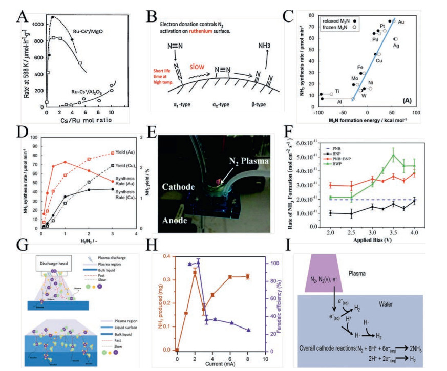
There are mainly two strategies to enhance the energy efficiency and conversion of the nitrogen fixation process. One is catalyst development, which primarily focuses on the presence, the kinds, and the structure of the catalysts [59-61]. For example, Aika proposed an activation mechanism for an alkali promoter for ruthenium catalysts [59]. The sponsors used in these studies are alkaline metals such as Cs, Ba, and K. Researchers found these promoters could increase the catalytic activity of the system by effectively suppressing N retardation on ruthenium surfaces, also, to promote N2 dissociation during the NH3 synthesis (Figs. 4A and B). Iwamoto and co-workers reported a wool-like gold electrode as a novel and very useful catalyst for ammonia synthesis using nonthermal atmospheric-pressure plasma [60]. Au was the most active catalyst among the studied catalysts (Fig. 4C), the appropriate instability of surface nitride on Au promoted the reaction of nitrogen and hydrogen. The study demonstrated that promising yields of ammonia could be obtained at low temperature and atmospheric pressure when a non-thermal plasma was operated in tandem with a catalyst (Fig. 4D). Moreover, Guo and co-workers reported a systematic review of the plasma-assisted ammonia synthesis under low temperature and pressure conditions. Furthermore, Guo and co-workers reported recent advances of the electrocatalytic ammonia synthesis catalyzed by a series of functional materials from electrolytes (including solid oxide, molten salt, polymer, and liquid electrolytes) had been summarized and discussed, along with the presentation and evaluation of catalyst preparation, reaction parameters and equipment [61].

|
Download:
|
| Fig. 4. (A) Rate of ammonia synthesis of 2 wt% Ru-CsOH/MgO (two separate sample experiments were done; filled circles and open squares) and 2 wt% Ru-CsOH/Al2O3 (open circles) as a function of Cs/Ru mol ratio; (B) Reaction mechanism for ammonia synthesis over ruthenium catalysts. Reproduced with permission [59]. Copyright 2017, Elsevier B.V. (C) Dependence of the respective initial activity of metal wool catalysts for ammonia synthesis on the formation energy of trinuclear nitride M3N; (D) Change in the synthesis rate and yield of ammonia as a function of the H2/N2 ratio using a wool-like gold or copper electrode. Reproduced with permission [60]. Copyright 2017, American Chemical Society. (E) Image of the electrolyzer by plasma-assist; (F) Ammonia production rate vs. applied bias for different conditions. Reproduced with permission [62]. Copyright 2018, The Royal Society of Chemistry. (G) The mechanism for the in situ jet plasma nitrogen fixation in the gas phase and at the liquid surface. Reproduced with permission [63]. Copyright 2018, The Royal Society of Chemistry. (H) Total NH3 produced and corresponding faradaic efficiency as a function of current after 45 min at pH 3.5; (I) Important species contained in the plasma and process of NH3 formation. Source: Reproduced with permission [64]. Copyright 2019, AAAS. | |
On the other hand, the proper reactor design could significantly improve the efficiency and conversion rate of the ammonia production system, which further represents a cleaner production of ammonia. Recently, Kumari and co-workers proposed a new plasma assisted strategy for N2 electrochemical reduction [62]. In this study, researchers incorporated nitrogen plasma into the cathode of ammonia synthesis unit to activate nitrogen species; subsequently, the excited N2 species would have the capability to electrochemically react with H+ atoms produced from water oxidation at the anode (Fig. 4E). When a bias of 3.5 V was applied, experimental data showed that plasma-assisted operation for the bias with plasma (BWP) achieved 47% more NH3 than the combination of bias with no plasma (BNP) and plasma with no bias (PNB) conditions (Fig. 4F). Besides, a sustainable atmospheric nitrogen fixation process was presented under climatic conditions and without introducing hydrogen or any catalyst by Peng and co-workers. The in situ spray-type plasma used in this study could significantly enhance the nitrogen fixation rate by up to two times. The fixation mechanism determined was a synergistic interaction between the gas and liquid phase (Fig. 4G) [63].
Also, a hybrid plasma electrolysis system without a catalytic material surface for studying NH3 formation had been developed by Hawtof and co-workers [64]. This strategy achieved high faradaic efficiency (up to 100%) at ambient temperature and pressure (Fig. 4H). In this study, by adjusting the pH of the solution and adding an electron-trapping agent, the researchers believed that this high selectivity results from the solvated electrons at the plasma-water solution interface, which preferentially reacted with protons to form hydrogen radicals (Fig. 4I). Electrocatalyst use and surface adsorption processes require adjustment of proton concentration and transport processes to improve performance further.
5. Plasma strategy for ORRThe cathodic oxygen reduction reaction is a critical process for fuel cells and metal-air batteries. Currently, the most excellent electrocatalysts for ORR are Pt-based noble metal catalysts because of their unique advantages to promote ORR. However, the high price, poor stability and low reserves on the earth of noble metalbased catalysts have limited the large-scale promotion of this renewable energy storage and conversion devices [17]. Therefore, it is significant to design and prepare noble metal-free electrocatalysts to replace or reduce the usage of the precious metal electrocatalysts. In this respect, carbon materials attract full attention due to their easy access, low prices, and strong tolerance to acidic and alkaline media. There are two strategies to enhance the ORR performance of carbon-based catalysts: one is increasing the specific surface area and active sites numbers through plasma etching, the other is doping the heteroatoms to tune the electronic structure [26].
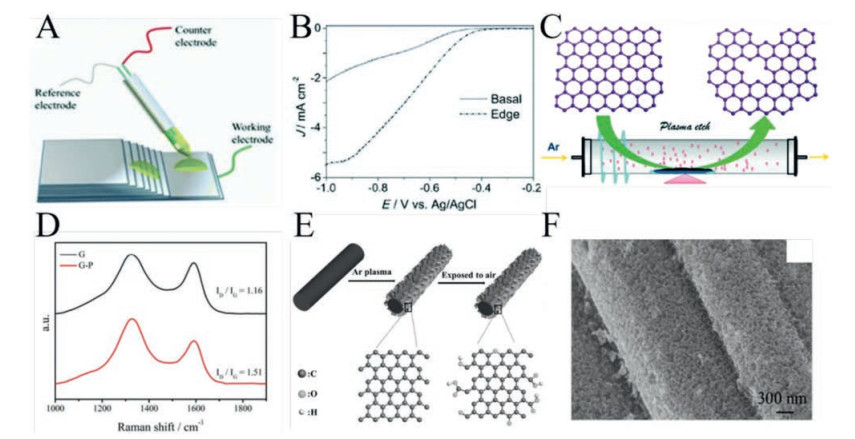
5.1. Intrinsic defects of the carbon materialSince Shen and co-workers demonstrated the edge of graphite has higher ORR catalytic activity than the basal plane through an electrochemical micro-operation platform (Fig. 5A) in 2014 [65], the intrinsic defects of carbon materials, including destruction of carbon rings, carbon atom vacancy, and structure distortion, have received considerable attention to improving ORR performance [26,39,66]. In Shen's work, researchers ingeniously studied the ORR reaction with an air-saturated tiny droplet (diameter ca. 15 mm) in an arbitrary position (including edges and bases) of highly oriented pyrolytic graphite (HOPG). Electrochemical measurements results provided direct evidence that edge carbon atoms have higher activity than basal-plane towards ORR (Fig. 5B).

|
Download:
|
| Fig. 5. (A) Micro-operation schematic illustration for the ORR experiment; (B) LSV curves for ORR on edge and the basal plane of the HOPG. Source: Reproduced with permission [65]. Copyright 2014, Wiley-VCH. (C) The synthetic schematic of the edge-rich and dopant-free graphene by using Ar plasma; (D) Raman spectra of G and G–P. Reproduced with permission [67]. Copyright 2016, The Royal Society of Chemistry. (E) Preparation schematic of in situ exfoliation of edge-rich and oxygen-functionalized graphene by plasma etching; (F) SEM images of P-CC. Reproduced with permission [68]. Copyright 2017, Wiley-VCH. | |
Subsequently, considering the critical influence of intrinsic defects in carbon nanomaterials on ORR, Tao and co-workers first designed and synthesized the edge-rich and dopant-free graphene as ORR electrocatalyst by Ar plasma (Fig. 5C) [67]. The plasma etching generated more edges and holes on graphene, which effectively increased the catalytic activity sites numbers for ORR. As shown in Fig. 5D, plasma etched graphene (designated as G–P) had a higher the ID/IG value (1.51) than that of original graphene (designated as G, 1.16), suggesting an enhancement of the disorder degree of the graphene by plasma etching. It proved that the plasma-assisted treatment could be an effective strategy to increase the defect sites. It indicated the significant influence of intrinsic defects on the electrocatalytic performance of carbon.
Moreover, Liu and co-workers reported the preparation of the edge-rich graphene from carbon fiber with the in-situ exfoliation strategy (Fig. 5E) [68]. The new Ar plasma exfoliated graphene with pores, and rich edges/defects exhibited an excellent electrolyte affinity due to the enhanced mass transport (Fig. 5F). Moreover, once contact with air or oxygen, those graphene nanosheets would react with oxygen and transfer to oxygen-functionalized graphene. Therefore, the obtained graphene nanosheets had a lower ORR overpotential than the original carbon cloth at 10 mA/cm2. This work also showed that plasma technology is an effective method to etch the surface of the material to produce more reactive sites. Based on the above, it can be concluded that intrinsic defects of carbon materials can improve the ORR performance of electrocatalysts due to larger specific surface areas, faster mass transports, better intrinsic electron conductivity, and more active sites.
5.2. Heteroatom-doped carbon materialsAs early as 2009, Dai and co-workers first discovered N-doped carbon nanotube array have a comparable ORR performance with Pt-based catalysts [69]. The Density functional theory (DFT) calculation explained that the unusual high ORR catalytic activity was directly related to higher positive charge density of adjacent carbon atoms induced by the strongly electron-withdrawing N atom. The nitrogen-doping not only changed the chemisorption of oxygen from the end-on adsorption to the side-on bridge-type adsorption on the surfaces of carbon materials but also weaken the O-O bonding energy, thereby it improved the ORR activity.
Since then, heteroatom-doped carbonmaterials, includingN, B, P, S, and so on, have attracted much attention [70-73]. Although there are many traditional methods for preparing heteroatom-doped carbon nanomaterials, including ball milling, hydrothermal and chemical vapor deposition, and so on, these methods usually demand high energy consumption and some relatively complicated preparationprocesses.Forinstance, usingureaanddicyandiamideas nitrogen precursors, Ratso and co-workers developed N-doped fewlayer graphene and multi-walled carbon nanotube hybrid materials as the ORR electrocatalyst by annealing the mixture of graphene oxide and multi-walled carbon nanotube in the presence of these nitrogen-containing compounds at a high temperature of 800 ℃ [74]. Li and co-workers also synthesized an S-doped carbon nanotube by calcining p-benzenedithiol and oxidized carbon nanotubes in a nitrogen atmosphere at 900 ℃ [75].
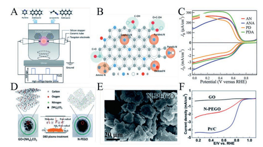
In contrast, an active and energy-saving method to prepare the heteroatom-doped carbon materials as the ORR electrocatalysts is plasma technology. Li and co-workers developed an N-doped carbon matrix via a solution plasma process at room temperature (Fig. 6A) [76]. In this work, pyridine and acrylonitrile were selected as the heterocyclic and linear structure precursor, respectively. A small amount of anthracene (7 mmol/L) was introduced as an additive to promote the graphitic structure in the carbon matrix further. These precursors dissociated into some active species (including C2, CH, H, N2, and CN) during plasma generation, followed by interaction and recombination, resulting in the formation of carbon nanoparticles with various bonding configurations (Fig. 6B). In terms of ORR electrocatalytic performance (Fig. 6C), the samples synthesized by mixing acrylonitrile and anthracene (designated as ANA) displayed a higher ORR onset potential and current density compared to other catalysts. It was because amino-N and graphitic-N might have a superior effect on ORR potential compared to pyridinic-N. Moreover, with the help of DBD plasma reactor, Wang and co-workers designed and prepared an N-doped and plasma exfoliated graphene oxide (N-PEGO) electrocatalyst for ORR (Fig. 6D) [77]. In this work, a hybrid material which is a certain amount of (NH4)2CO3 was embedded in the interlayer of the graphene oxide (GO), was used as a precursor. Subsequently, the precursor was placed in the DBD plasma reactor and treated for 10 min, the doped and exfoliated graphene oxides were obtained. N-PEGO exhibited excellent stability under alkaline conditions, which was mainly attributed to the relatively high nitrogen content of the catalyst (5.26 at%). Moreover, the exfoliated graphene oxide (<4 layers) possessed a large specific surface area (Fig. 6E), which ensured a sufficient number of ORR active sites. Therefore, the ORR activity of the prepared N-PEGO could be comparable with that of commercial Pt/C catalysts (Fig. 6F).

|
Download:
|
| Fig. 6. (A) Schematic image of the experimental setup with various types of precursors; (B) different bonding configurations in N-doped carbon; (C) LSV curves for ORR of all samples (the samples synthesized from pyridine and acrylonitrile are denoted as PD and AN, respectively. The samples synthesized by mixing pyridine and anthracene were designated as PDA). Reproduced with permission [76]. Copyright 2018, The Royal Society of Chemistry. (D) Schematic illustration of the nitrogen doping of N-PEGO by DBD reactor; (E) SEM images of N-PEGO; (F) LSV curves of GO, N-PEGO and 20% Pt/C. Reproduced with permission [77]. Copyright 2018, The Royal Society of Chemistry. | |
Totally, plasma technology is an efficient and energy-saving method for etching, exfoliating, and doping carbon-based materials, which would help the large-scale preparation of heteroatom-doped carbon-based nanomaterials. However, under the influence of plasma technology, how to accurately control and optimize the doping concentration of heteroatoms, the mechanism of doping of different heteroatoms need further research in the oxygen reduction process.
6. Plasma strategy for OEROxygen evolution reaction (OER) is a vital electrode reaction in water-splitting and metal-air batteries [78]. However, due to the sluggish kinetics of the reaction, highly active electrocatalysts are urgently required to accelerate the reaction. To date, expensive metal-based oxide (including ruthenium oxide and iridium oxide) have been considered to be the most excellent OER electrocatalysts. Unfortunately, the large-scale application of these precious metal oxide electrocatalysts was severely limit due to excessively high prices, low reserves on the earth and instability during the oxidation reaction [78]. Therefore, numerous OER electrocatalysts were designed and prepared using abundant transition metal-based materials, including Co, Fe, and Ni. However, bulk materials are almost inertforOER because of their poor electrical conductivityand limited active sites [79]. Various strategies have been employed to enhance the electrocatalytic performance of the bulk electrocatalysts for OER, such as synthesizing specific nanostructures and tuning their electronic structure. Recent research indicated that plasma technology is a useful tool to modify these electrocatalysts to increase electric conductivity and created more active sites for OER. For example, it can be used to produce some defects (including vacancies and doping), etch and exfoliate bulk 2D layered materials [80]. Also, plasma can create some coordinately unsaturated metal sites and other new active species in metal-organic frameworks (MOFs) as catalytic centers for OER [81].
6.1. Transition metal compoundsGenerally, there are two main ways to enhance the electrocatalytic performance of bulk cobalt oxides for OER. One is to improve the specific surface area, and the other is to increase conductivity by adjusting the electronic states [82,83]. Recently, a review which summarized these various methods to enhance the electrocatalytic performance of transition metal compounds was reported [84].
Ma and co-workers synthesized hybrid porous nanowire arrays composed of interacting Co3O4 and carbon as OER electrocatalysts by carbonization of the MOFs grown on Cu foil [82]. Wang and co-worker demonstrated a solution reduction method to create oxygen vacancies on the Co3O4 surface and thus to effectively enhance electrochemical performance for OER [85]. However, the preparation of these catalysts is relatively complicated and timeconsuming. Recently, plasma strategy has been widely used to improve transition metal compounds catalysts. For example, Dou and co-workers reported the etching and nitrogen-doped composite material of Co9S8 and graphene (N-Co9S8/G) as an outstanding oxygen electrocatalyst by NH3 plasma treatment [86]. The NH3 plasma treatment on Co9S8/G had two main effects; one was the active N species generated from NH3 plasma could be successfully doped into Co9S8 and graphene, which played an important role in tuning the electronic structure of the electrocatalyst efficiently, the other was plasma could etch the surface of both. This etching effect made the electrocatalyst obtain a higher number of active sites. Therefore, the as-prepared N-Co9S8/G possessed highly activity for OER.
Moreover, Xu and co-workers prepared highly active Co3O4 nanosheets as OER electrocatalysts with a large surface area and abundant oxygen vacancies by plasma-engraving strategy [79]. First, Co3O4 nanosheets were obtained from cobalt hydroxides which were electrodeposited on titanium foil by thermally annealed in air. Then, the Co3O4 nanosheets array was treated by Ar plasma to create the oxygen vacancies. It is worth emphasizing that the plasma treatment time of only 120 s with the power of 100 W while it usually spent more than one hour to modify the catalysts by the traditional solution reduction method [85]. The plasma treatment not only led to the larger surface area but also created oxygen vacancies on Co3O4 surface due to the formation of new Co2+. It increased the number of active sites, improved the electronic conductivity, and tuned the electronic structure for OER. Compared with the pristine Co3O4, the plasmatreated Co3O4 possessed a lower onset potential and a much higher current density. Recently, Wang and co-workers reported an orthorhombic ultrathin CoSe2 nanosheets catalyst (o-CoSe2-O UNs) for OER. The Ar/O2 plasma was used to simultaneously induced exfoliation, surface reorganization (formation of an oxidative layer with rich oxygen vacancies), and phase transformation (cubic-to-orthorhombic) to generate o-CoSe2-O UNs (Figs. 7A and B) [87]. With the help of plasma, o-CoSe2-O UNs had an ultra-thin nanostructure (around 3.6 nm) and rich oxygen vacancies which optimized the electronic structure of the electrocatalyst, given a much improved OER performance and stability (Fig. 7C). It is noteworthy that o-CoSe2-O UNs only required an overpotential of 251 mV to reach the current density of 10 mA/cm2, which was superior to commercial RuO2 and most reported top-performing OER catalysts.

|
Download:
|
| Fig. 7. (A) Preparation illustration of o-CoSe2-O UNs; (B) XRD patterns of c-CoSe2/DETA and o-CoSe2-O UNs; (C) stability test of o-CoSe2-O UNs for OER. Reproduced with permission [87]. Copyright 2018, Wiley-VCH. (D) STEM-EDX mapping of original SnCoFe and the plasma treated SnCoFe; (E) TEM image and corresponding SAED patterns of original SnCoFe and the plasma treated SnCoFe; (F) LSV polarization curves of all samples. Reproduced with permission [88]. Copyright 2018, Wiley-VCH. (G) Description of the preparation of CoFe LDH nanosheets by plasma treatment; (H) The corresponding height curves of original SnCoFe and the plasma treated SnCoFe from AFM images; (I) LSV curves for OER on original CoFe LDH and the Ar plasma engraved CoFe LDH nanosheets. Reproduced with permission [80]. Copyright 2017, Wiley-VCH. | |
Compared with anion vacancies in metal oxides, the selective generation of cation vacancies is complicated. In this respect, Chen and co-workers successfully discovered the possibility of generating Sn vacancies in the SnCoFe perovskite hydroxide with the assistance of plasma technology [88]. After plasma treatment, the researchers observed that Sn elemental content was significantly lower than Fe and Co (Fig. 7D), indicating the existence of Sn vacancies. It could be because Sn(OH)4 has the relatively low lattice energy and weaker chemical bonds, thereby exposing energetically more active sites of CoFe species for OER, which led to the formation of an amorphous structure (Fig. 7E). On the one hand, these amorphous structures could effectively regulate the surface electronic structure of the electrocatalyst; on the other hand, could reduce the coordination numbers of active sites. As expected, the obtained electrocatalyst only needed an overpotential of 270 mV at a current density of 10 mA/cm2 (Fig. 7F).
6.2. Layered double hydroxides (LDHs)Layered double hydroxides (LDHs), a 2D layered material, have been extensively studied for OER due to the adjustable composition, structure, and morphology [89-92]. However, the stacking structure of bulk LDHs was rarely used as OER catalysts due to their low electronic conductivity and limited active sites [93,94]. Therefore, the exfoliation is necessary to expose more active sites, while the defects induced by the exfoliation process would modify the electronic state of LDHs.
For the first time, Liu and co-workers reported an ultrathin CoFe LDHs nanosheets with multivacancy as OER electrocatalysts by water-plasma-enabled exfoliation. The water plasma can cause fast peeling and produce multivacancy in the as-exfoliated ultrathin LDHs nanosheets. The increased active sites and the multivacancy significantly contribute to the enhanced electrocatalytic activity for OER [95]. Compared with the conventional liquid exfoliation methods [90,91], the water-plasma-enabled exfoliation is simple but effective, safe, non-toxic and time-saving. Moreover, this method can avoid the adsorption of liquid and use some toxic chemicals. Inspired by the last work, the same group reported ultrathin LDH nanosheets with multiple vacancies (including O, Co, and Fe vacancies) in the ultrathin 2D nanosheets through Ar plasma etching (Fig. 7G) [80].
In the above two work, the gas plasma treatment is more pure and efficient, and the post-treatment of the catalyst is more straightforward than the liquid plasma. Since the ultrathin nanosheet structure exposed a higher number of reactive sites for OER (Fig. 7H) and generated various vacancies can effectively improve the surface charge distribution, reduce the coordination numbers, and increase the disorder in the ultrathin nanosheets, the obtained CoFe LDH nanosheets exhibited a fantastic OER performance with a low overpotential of 266 mV at a current density of 10 mA/cm2 (Fig. 7I). Moreover, Wang and co-workers developed Ndoped and edge rich ultrathin CoFe LDHs nanosheets by N2 plasma [96]. The as-prepared electrocatalyst showed a high performance for OER and possessed a low overpotential of 233 mV at the current density of 10 mA/cm2.
As can be seen, plasma technology and strategy have been widely used in the preparation of electrocatalysts, such as doping, generating anionic/cationic vacancies, etching, and exfoliating catalysts.
6.3. Derived from metal–organic frameworksMetal-organic frameworks (MOFs), an emerging porous solid material, have captured widespread interest and achieved the explosive development over the past two decades [97,98]. Especially, electrocatalysts derived from MOFs have been widely developed because of their regular structures, highly tunable pore sizes (usually 0–3 nm, up to 9.8 nm) and diversified pore surfaces (BET, usually >1000 m2/g, up to 7000 m2/g) [97]. These features are of vital importance for improving the catalytic properties of MOFs.
Recently, Dou and co-workers have successfully on-site generated the atomic-scale CoOx species in the MOFs by O2 plasma treatment (Fig. 8A) [99]. In this study, O2 plasma partially broken the Co-N coordination bonds in the MOFs and then the generated Co species reacted with O2 produced atomic-scale CoOx species in the MOFs. Highly active CoOx species provided the active sites to catalyze the OER. Meanwhile, the abundant surface area and rough surface generated by plasma etching in MOFs ensure sufficient mass transport during OER (Fig. 8B). The element mapping of Co, O, C, and N in CoOx-ZIF suggested that as-formed CoOx species by O2 plasma were of atomic-scale with excellent dispersion (Fig. 8C). Therefore, compared with the pristine ZIF-67, atomic-scale CoOx Species in MOFs required a lower onset potential (Fig. 8D). XPS results confirmed that the bonding of Co-N was partially destroyed after plasma and the Co atoms were coordinated with O atoms to form CoOx species under the O2 atmosphere (Fig. 8E). Moreover, X-ray absorption near edge structure (XANES) and extended X-ray absorption fine structure (EXAFS) demonstrated that the Co K-edge is mainly originated from the electron transition from Co s to Co 4p unoccupied orbitals, suggesting the formation of Co-O bond (Fig. 8F). It was observed that the catalyst by using plasma treatment could produce some new species as active sites.

|
Download:
|
| Fig. 8. (A) Schematic of the preparation of CoOx-ZIF; (B) SEM images of CoOx-ZIF; (C) Element mapping of Co, O, C, and N in CoOx-ZIF; (D) LSV curves for OER of all samples; (E) Co 2p3/2 XPS peaks of ZIF-67 and CoOx-ZIF; (F) XANES and EXAFS spectra of CoOx-ZIF and ZIF-67. Reproduced with permission [99]. Copyright 2017, Wiley-VCH. (G) Preparation schematic of Co-PBA; (H) The structure of Co-PBA with composition Co3(Fe(CN)6)2; (I) LSV curves for OER of pristine and plasma-treated Co-PBA samples. Reproduced with permission [100]. Copyright 2018, Wiley-VCH. | |
With the DBD reactor under N2 atmosphere, Tao and co-workers ingeniously prepared coordinated unsaturated metal sites in the MOFs as active sites to accelerate OER [81]. During plasma etching, N2 plasma partially destroyed ligands combined with Co atoms in ZIF-67 to generate coordinately unsaturated metal sites. Both experimental data and theoretical calculations indicated the unsaturated metal sites played an essential role in the high catalytic activity for OER.
Subsequently, with the help of low-temperature air plasma treatments, non-destructive activation of metal sites in the framework has been reported by Guo and co-workers (Fig. 8G) [100]. The cryogenic air plasma contains highly reactive oxygen, including atomic oxygen and molecular oxygen in an excited state and these activesarenon-thermal.The combinationofhigh chemical reactivity and low thermal effects allow selective modification of the metal sites without damaging the framework structure. The framework of this study is a Fe/Co double metal cyanide composed of cyanide-bridged Fe and Co cations. Highly reactive oxygen species generated by low temperature-air plasma activated metal sites for OER in Co-based Prussian blue analogues (Co-PBA) by oxygen bonding to the metal sites (Fig. 8H). The framework-based OER catalyst possessed a very low overpotential of 330 mV at a high current density of 100 mA/cm2 due to highly active and distributed metal catalytic sites in the nanoporous framework (Fig. 8I).
7. Plasma strategy for HERHydrogen is considered to be the most promising alternative to petrochemicals in the future since it is clean, efficient and recyclable [101,102]. Electrolysis/photolysis hydrogen production technology is a meaningful way to obtain hydrogen energy on a large scale [103]. However, the scarcity and high cost of hydrogen evolution (HER) electrocatalysts which are usually precious metals Pt, Pd severely hinder the large-scale application and development of hydrogen energy [17]. Therefore, researchers turned the focus to non-precious metal-based catalysts, including transition metal sulfides, phosphides and some catalysts derived from metal oxides [104]. Developing the efficient, stable and inexpensive watersplitting catalyst has become a frontier topic in the field of energy conversion research.
7.1. Transition metal sulfides and phosphidesTransition metal sulfides and phosphides have received extensive attention due to their excellent HER catalytic activity and unique physical and chemical properties. At present, many strategies have been used to improve the electrocatalytic performance of these materials, including regulating active sites (exposing more active sites, increasing the activity of single active site and developing the contact of active sites with electrolyte) and improving the electrical conductivity (composite with conductive materials). Currently, plasma technology is considered as an effective method to modify these materials. In this area, Tao and co-workers have used an Ar or O2 plasma assisted strategy to develop the MoS2 thin films as an efficient electrocatalyst for the HER (Fig. 9A) [105]. After Ar or O2 plasma treatment, physical and chemical defects, which exposed the higher number of active sites, generated in MoS2 thin films. Also, the surface morphology of MoS2 could be tuned by controlling the plasma treatment time. The increased active sites number and properly surface morphology would benefit the electrocatalytic activity for the HER.

|
Download:
|
| Fig. 9. (A) Illustration of the preparation of plasma treatment of MoS2 thin films. Reproduced with permission [105]. Copyright 2015, The Royal Society of Chemistry. (B) The HRTEM images of CoP nanowires with 40 s of oxygen plasma etching; (C) LSV curves of CoP NWs/CC with different oxygen plasma engraving time; (D) XANES spectra of CoP nanowires and CoP NWs 40 s. Reproduced with permission [106]. Copyright 2018, Wiley-VCH. | |
Subsequently, Xu and co-workers reported surface-reorganization CoP nanowires grown on carbon clothes (CoP NWs/CC) as a high-performance electrocatalyst for HER [107]. In this work, oxygen plasma was applied to generate CoP/CoOx interface on CoP NWs/CC with an etch time of only 40 s (Fig. 9B). Notably, compared with the pristine CoP NWs/CC, the prepared CoP NWs/CC with CoP/ CoOx interface achieved significant improvement of a reduced overpotential of 180 mV at the current density of 100 mA/cm2 (Fig. 9C). Generated interface benefited the HER in alkaline media, the XANES result (Fig. 9D) possessed a pre-edge peak in pristine CoP nanowires, which was ascribed to the cobalt alloy. It became weaker and shifted to higher energy, indicating that the surface oxidation of CoP occurred, and the chemical valence of cobalt became higher after plasma treatment.
7.2. Derived from transition metal oxidesTransitional metal oxides are often used as OER electrocatalysts due to their various nanostructures such as nanosheets, nanoflowers, and nanospheres [107]. Recently, studies have shown that transition metal oxides can be used as HER electrocatalysts after plasma modification. This is because plasma technology increases the number of reactive sites, improves electrocatalytic performance, and so on.
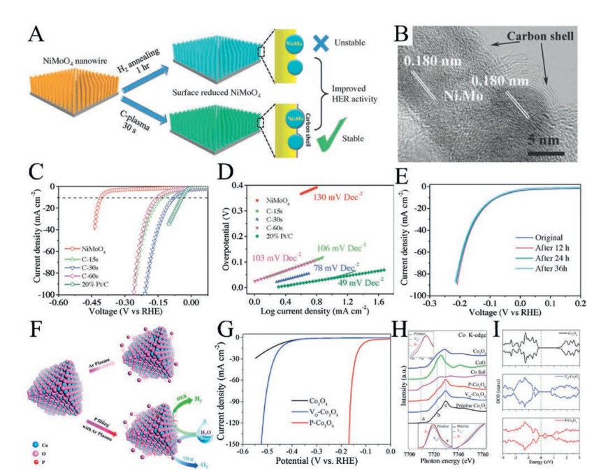
Using transition metal oxides as precursors, Zhang and co-workers boosted the HER catalytic activity via carbon plasma modification (Fig. 10A) [108]. In this study, the researchers first placed the NiMoO4 nanowire array on a carbon cloth and then performed C-plasma treatment for 30 s. Under the action of carbon plasma reduction, NiMoO4 was partially reduced to form high active Ni4Mo species for HER. Surprisingly, the structure of the oxide nanowire array was well maintained, which was mainly attributed to the concise processing time. At the same time, a thin layer of carbon shell grown on the surface of the nanowire array in the process of C-plasma treatment (Fig. 10B), which ensured the stability of the catalyst during HER due to its oxidation resistance. Therefore, the prepared active Ni4Mo nanoparticles with a thin layer of carbon shell had a relatively low overpotential of 76 mV to achieve the current density of 10 mA/cm2 (Fig. 10C). Moreover, as obtained electrocatalyst had better kinetics and stability, as shown in Figs. 10D and E.

|
Download:
|
| Fig. 10. (A) Schematic of the synthesis of C-plasma treated and H2 annealed NiMoO4; (B) TEM images of C-plasma treated NiMoO4 for 30 s; (C) LSV curves of samples with different plasma engraving time; (D) Tafel slopes of all samples; (E) Stability test of C-plasma treated NiMoO4 electrode for 30 s under different HER test stage. Reproduced with permission [108]. Copyright 2018, Wiley-VCH. (F) Schematic of the preparation of P-Co3O4 and VO-Co3O4 by using plasma approach; (G) LSV curves for HER of all samples; (H) XANES spectra of pristine Co3O4, VO-Co3O4, and P-Co3O4; (I) Computed density of states of pristine Co3O4, VO-Co3O4, and P-Co3O4 systems, the green dashed lines denote Fermi level. Reproduced with permission [109]. Copyright 2017, The Royal Society of Chemistry. | |
In previous works, it has been proven that Co3O4 has good activity for OER [79]. Recently, scientists have determined that Co3O4 is also an excellent HER electrocatalyst after plasma modification. Xiao and co-workers, for the first time, successfully filled the in situ-generated oxygen vacancies in Co3O4 with phosphorus through a facile plasma strategy to generate an electrocatalyst for the overall water splitting with excellent stability (Fig. 10F) [109]. During the Ar plasma treatment, NaH2PO2 was evaporated and filled the in situ-generated oxygen vacancies in the Co3O4 with P (designated as P-Co3O4), which may effectively increase the electrical conductivity of the electrocatalyst. Therefore, to achieve a current density of 10 mA/cm2, the prepared Co3O4 nanosheet only needed overpotentials of 120 mV for HER and 280 mV for OER (Fig. 10G). In XANES measurement, there was a distinct shift to lower energy in Co3O4 with oxygen vacancies (designated as VO-Co3O4) compared to the pristine Co3O4, indicating the generation of oxygen vacancies. When the oxygen vacancies were filled by P, the energy shifted back to a relatively higher value (Fig. 10H), suggesting that the oxygen vacancies were successfully filled by P. However, the intensity of was P-Co3O4 lower than the pristine Co3O4. The reason is that the electronegativity of P is smaller than that of O. Besides, computing the density of states results displayed that P-Co3O4 had better electrical conductivity than VO-Co3O4 and pristine Co3O4 (Fig. 10I). Theoretical calculations indicated that the oxygen vacancies substituted by P could enhance the electrical conductivity, which further improved the HER and OER catalytic performance of Co3O4. From the above work, it can be seen that plasma technology is an effective way to modify the catalyst by etching the surface of the material, creating phase interfaces and new active species, constructing and filling vacancies, and so on.
8. Summary and outlookIn summary, significant development has been achieved in the field of energy storage and conversion by using plasma technology over the past few years. Recent advances in plasma technology and strategy for electrocatalysts modification and preparation have been presented here. From the above discussion and analysis, plasma technology has been extensively used in the design and synthesis of electrocatalysts including carbon-based materials, transition metal oxide/phosphide/sulfides, and metal-organic frameworks (MOFs). It has been demonstrated that these electrocatalysts have an excellent activity for CO2RR, N2 fixation, ORR, OER, and HER. To date, although lots of articles have reported on electrocatalysts prepared by using plasma, emerging plasmaassisted electrocatalyst preparation technology is still just beginning. To the best of our knowledge, there are still many enormous challenges related to the deep understanding of plasma physics and chemistry:
(1) With the continuous development and maturity of plasma technology, it needs to accurately control the size, the structure, and defect concentrations of these electrocatalysts.
(2) Since plasma technology has various applications, such as preparation, modification, and synthesis, it is especially important to design and optimize plasma reactors based on the purpose.
(3) Since the modified electrocatalysts generated by plasma is highly active during the reaction process, in situ characterizations of the active sites become more difficult. Therefore, it needs to develop some advanced physical characterization techniques to track these evolution in the electronic structure and microstructure.
In short, plasma technology will be more and more widely used in the preparation of a variety of nanocatalysts soon. With the full application of plasma technology in the field of electrocatalysis, there is no doubt that it will promote a deep understanding of the theoretical study of plasma physics and chemistry.
AcknowledgementsThis work was supported by the National Natural Science Foundation of China (Nos. 51402100 and 21573066) and the Provincial Natural Science Foundation of Hunan (Nos. 2016JJ1006 and 2016TP1009).
| [1] |
B. Bayatsarmadi, Y. Zheng, A. Vasileff, S.Z. Qiao, Small 13 (2017) 1700191. DOI:10.1002/smll.v13.21 |
| [2] |
Y. Zheng, J. Wang, B. Yu, et al., Chem. Soc. Rev. 46 (2017) 1427-1463. DOI:10.1039/C6CS00403B |
| [3] |
H. Liang, F. Ming, H.N. Alshareef, Adv. Energy Mater. 8 (2018) 1801804. DOI:10.1002/aenm.v8.29 |
| [4] |
Z.L. Wang, D. Xu, H.X. Zhong, et al., Sci. Adv. 1 (2015) e1400035. DOI:10.1126/sciadv.1400035 |
| [5] |
Y. Jiao, Y. Zheng, M. Jaroniec, S.Z. Qiao, Chem. Soc. Rev. 44 (2015) 2060-2086. DOI:10.1039/C4CS00470A |
| [6] |
Z.L. Wang, D. Xu, J.J. Xu, X.B. Zhang, Chem. Soc. Rev. 43 (2014) 7746-7786. DOI:10.1039/C3CS60248F |
| [7] |
Y. Zheng, W. Zhang, Y. Li, et al., Nano Energy 40 (2017) 512-539. DOI:10.1016/j.nanoen.2017.08.049 |
| [8] |
Y.P. Zhu, C. Guo, Y. Zheng, S.Z. Qiao, Acc. Chem. Res. 50 (2017) 915-923. DOI:10.1021/acs.accounts.6b00635 |
| [9] |
C. Li, H. Tan, J. Lin, et al., Nano Today 21 (2018) 91-105. DOI:10.1016/j.nantod.2018.06.005 |
| [10] |
Y. Xiong, Y. Yang, F.J. DiSalvo, H.D. Abruna, J. Am. Chem. Soc. 140 (2018) 7248-7255. DOI:10.1021/jacs.8b03365 |
| [11] |
Y. Nie, L. Li, Z. Wei, Chem. Soc. Rev. 44 (2015) 2168-2201. DOI:10.1039/C4CS00484A |
| [12] |
B. Xiong, L. Chen, J. Shi, ACS Catal. 8 (2018) 3688-3707. DOI:10.1021/acscatal.7b04286 |
| [13] |
H.F. Wang, C. Tang, Q. Zhang, Adv. Funct. Mater. 28 (2018) 1803329. DOI:10.1002/adfm.v28.46 |
| [14] |
X. Liu, L. Dai, Nat. Rev. Mater. 1 (2016) 16064. DOI:10.1038/natrevmats.2016.64 |
| [15] |
J. Zhang, Z. Zhao, Z. Xia, L. Dai, Nat. Nanotechnol. 10 (2015) 444-452. DOI:10.1038/nnano.2015.48 |
| [16] |
B. Wang, X. Cui, J. Huang, R. Cao, Q. Zhang, Chin. Chem. Lett. 29 (2018) 1757-1767. DOI:10.1016/j.cclet.2018.11.021 |
| [17] |
S. Zhao, D.W. Wang, R. Amal, L. Dai, Adv. Mater. (2018) 1801526. |
| [18] |
C. Chen, D. Yan, Y. Wang, et al., Small (2019) e1805029. |
| [19] |
L. Wang, Y. Yi, C. Wu, H. Guo, X. Tu, Angew. Chem. Int. Ed. 56 (2017) 13679-13683. DOI:10.1002/anie.201707131 |
| [20] |
Y. Richardson, J. Blin, A. Julbe, Prog. Energy Combust. Sci. 38 (2012) 765-781. DOI:10.1016/j.pecs.2011.12.001 |
| [21] |
Á. Martín, A. Navarrete, M.D. Bermejo, J. Supercrit. Fluids 134 (2018) 141-149. DOI:10.1016/j.supflu.2017.11.021 |
| [22] |
G. Akay, K. Zhang, Ind. Eng. Chem. Res. 56 (2017) 457-468. DOI:10.1021/acs.iecr.6b02053 |
| [23] |
B. Ouyang, Y. Zhang, Z. Zhang, H.J. Fan, R.S. Rawat, Small 13 (2017) 1604265. DOI:10.1002/smll.v13.34 |
| [24] |
D. Yan, H. Li, C. Chen, Y. Zou, S. Wang, Small Methods (2018) 1800331. DOI:10.1002/smtd.201800331 |
| [25] |
Y. Wang, D. Yan, S. El Hankari, Y. Zou, S. Wang, Adv. Sci. 5 (2018) 1800064. DOI:10.1002/advs.v5.8 |
| [26] |
S. Dou, L. Tao, R. Wang, et al., Adv. Mater. 30 (2018) e1705850. DOI:10.1002/adma.v30.21 |
| [27] |
A. Bogaerts, E.C. Neyts, ACS Energy Lett. 3 (2018) 1013-1027. DOI:10.1021/acsenergylett.8b00184 |
| [28] |
Z. Wang, Y. Zhang, E.C. Neyts, et al., ACS Catal. 8 (2018) 2093-2110. DOI:10.1021/acscatal.7b03723 |
| [29] |
J. Keil, Frerich, Int. Rev. Chem. Eng. 34 (2018) 135-200. DOI:10.1515/revce-2017-0085 |
| [30] |
J.H. Koh, H.S. Jeon, M.S. Jee, et al., J. Phys. Chem. C 119 (2015) 883-889. |
| [31] |
P. Peng, P. Chen, C. Schiappacasse, et al., J. Clean. Prod. 177 (2018) 597-609. DOI:10.1016/j.jclepro.2017.12.229 |
| [32] |
L. Fang, D. Hallam, R. Bermúdez, Energy Build. 130 (2016) 238-243. DOI:10.1016/j.enbuild.2016.08.035 |
| [33] |
J.S. Jung, J.G. Kim, J. Electrost. 86 (2017) 12-17. DOI:10.1016/j.elstat.2016.12.011 |
| [34] |
J.E. Foster, Phys. Plasmas 24 (2017) 055501. DOI:10.1063/1.4977921 |
| [35] |
X. Ji, X. Yuan, J. Wu, et al., ACS Appl. Mater. Interfaces 9 (2017) 24616-24624. DOI:10.1021/acsami.7b06637 |
| [36] |
H. Cheng, J. Fan, Y. Zhang, D. Liu, K. Ostrikov, Catal. Today (2018). DOI:10.1016/j.cattod.2018.11.026 |
| [37] |
W. Gu, L. Hu, X. Zhu, et al., Chem. Commun. (Camb.) 54 (2018) 12698-12701. DOI:10.1039/C8CC06399K |
| [38] |
B. Cui, B. Hu, J. Liu, et al., ACS Appl. Mater. Interfaces 10 (2018) 23858-23873. DOI:10.1021/acsami.8b06568 |
| [39] |
D. Yan, Y. Li, J. Huo, et al., Adv. Mater. 29 (2017) 1606459. DOI:10.1002/adma.v29.48 |
| [40] |
C.J. Liu, G.P. Vissokov, B.W.L. Jang, Catal. Today 72 (2002) 173-184. DOI:10.1016/S0920-5861(01)00491-6 |
| [41] |
Boutonnet Kizling M., S.G. Järås, Appl. Catal. A Gen. 147 (1996) 1-21. DOI:10.1016/S0926-860X(96)00215-3 |
| [42] |
S. Samal, J. Clean. Prod. 142 (2017) 3131-3150. DOI:10.1016/j.jclepro.2016.10.154 |
| [43] |
Q. Jiang, H. Zhang, S. Wang, Green Chem. 18 (2016) 662-666. DOI:10.1039/C5GC01563D |
| [44] |
S. Back, J. Lim, N.Y. Kim, Y.H. Kim, Y. Jung, Chem. Sci. 8 (2017) 1090-1096. DOI:10.1039/C6SC03911A |
| [45] |
D. Zhu, J. Liu, S.Z. Qiao, Adv. Mater. 28 (2016) 3423-3452. DOI:10.1002/adma.201504766 |
| [46] |
K. Zhao, Y. Liu, X. Quan, S. Chen, H. Yu, ACS Appl. Mater. Interfaces 9 (2017) 5302-5311. DOI:10.1021/acsami.6b15402 |
| [47] |
S. Liu, H. Tao, Q. Liu, et al., ACS Catal. 8 (2018) 1469-1475. DOI:10.1021/acscatal.7b03619 |
| [48] |
Y. Song, W. Chen, C. Zhao, et al., Angew. Chem. Int. Ed. 56 (2017) 10840-10844. DOI:10.1002/anie.201706777 |
| [49] |
Z. Gu, H. Shen, L. Shang, et al., Small Methods 2 (2018) 1800121. DOI:10.1002/smtd.v2.11 |
| [50] |
Z. Gu, N. Yang, P. Han, et al., Small Methods (2018) 1800449. DOI:10.1002/smtd.201800449 |
| [51] |
H. Mistry, A.S. Varela, C.S. Bonifacio, et al., Nat. Commun. 7 (2016) 121123. |
| [52] |
D. Gao, I. Zegkinoglou, N.J. Divins, et al., ACS Nano 11 (2017) 4825-4831. DOI:10.1021/acsnano.7b01257 |
| [53] |
H. Mistry, Y.W. Choi, A. Bagger, et al., Angew. Chem. Int. Ed. 56 (2017) 11394-11398. DOI:10.1002/anie.201704613 |
| [54] |
V. Kyriakou, I. Garagounis, E. Vasileiou, A. Vourros, M. Stoukides, Catal. Today 286 (2017) 2-13. DOI:10.1016/j.cattod.2016.06.014 |
| [55] |
G.F. Chen, S. Ren, L. Zhang, et al., Small Methods (2018) 1800337. DOI:10.1002/smtd.201800337 |
| [56] |
M. Li, H. Huang, J. Low, et al., Small Methods (2018) 1800388. DOI:10.1002/smtd.201800388 |
| [57] |
R.F. Service, Science 361 (2018) 120. |
| [58] |
H. Uyama, O. Matsumoto, Plasma Chem. Plasma Process. 9 (1989) 13-24. DOI:10.1007/BF01015824 |
| [59] |
K. Aika, Catal. Today 286 (2017) 14-20. DOI:10.1016/j.cattod.2016.08.012 |
| [60] |
M. Iwamoto, M. Akiyama, K. Aihara, T. Deguchi, ACS Catal. 7 (2017) 6924-6929. DOI:10.1021/acscatal.7b01624 |
| [61] |
X. Guo, Y. Zhu, T. Ma, J. Energy Chem. 26 (2017) 1107-1116. DOI:10.1016/j.jechem.2017.09.012 |
| [62] |
S. Kumari, S. Pishgar, M.E. Schwarting, W.F. Paxton, J.M. Spurgeon, Chem. Commun. (Camb.) 54 (2018) 13347-13350. DOI:10.1039/C8CC07869F |
| [63] |
P. Peng, P. Chen, M. Addy, et al., Chem. Commun. (Camb.) 54 (2018) 2886-2889. DOI:10.1039/C8CC00697K |
| [64] |
R. Hawtof, S. Ghosh, E. Guarr, et al., Sci. Adv. 5 (2019) eaat5778. DOI:10.1126/sciadv.aat5778 |
| [65] |
A. Shen, Y. Zou, Q. Wang, et al., Angew. Chem. Int. Ed. 53 (2014) 10804-10808. DOI:10.1002/anie.201406695 |
| [66] |
J. He, Y. Zou, S. Wang, Dalton Trans. 48 (2019) 15-20. DOI:10.1039/C8DT04026E |
| [67] |
L. Tao, Q. Wang, S. Dou, et al., Chem. Commun. (Camb.) 52 (2016) 2764-2767. DOI:10.1039/C5CC09173J |
| [68] |
Z. Liu, Z. Zhao, Y. Wang, et al., Adv. Mater. 29 (2017) 1606207. DOI:10.1002/adma.201606207 |
| [69] |
K. Gong, F. Du, Z. Xia, M. Durstock, L. Dai, Science 323 (2009) 760. DOI:10.1126/science.1168049 |
| [70] |
H. Jin, J. Wang, D. Su, et al., J. Am. Chem. Soc. 137 (2015) 2688-2694. DOI:10.1021/ja5127165 |
| [71] |
J. Liang, Y. Jiao, M. Jaroniec, S.Z. Qiao, Angew. Chem. Int. Ed. 124 (2012) 11664-11668. DOI:10.1002/ange.201206720 |
| [72] |
L. Qu, Y. Liu, J.B. Baek, L. Dai, ACS Nano 4 (2010) 1321-1326. DOI:10.1021/nn901850u |
| [73] |
L. Yang, S. Jiang, Y. Zhao, et al., Angew. Chem. Int. Ed. 50 (2011) 7132-7135. DOI:10.1002/anie.v50.31 |
| [74] |
S. Ratso, I. Kruusenberg, M. Vikkisk, et al., Carbon 73 (2014) 361-370. DOI:10.1016/j.carbon.2014.02.076 |
| [75] |
W. Li, D. Yang, H. Chen, Y. Gao, H. Li, Electrochim. Acta 165 (2015) 191-197. DOI:10.1016/j.electacta.2015.03.022 |
| [76] |
O.L. Li, S. Chiba, Y. Wada, G. Panomsuwan, T. Ishizaki, J. Mater. Chem. A 5 (2017) 2073-2082. DOI:10.1039/C6TA08962C |
| [77] |
Y. Wang, F. Yu, M. Zhu, et al., J. Mater. Chem. A 6 (2018) 2011-2017. DOI:10.1039/C7TA08607E |
| [78] |
A. Xu, C. Dong, A. Wu, et al., J. Mater. Chem. A 7 (2019) 4581-4595. DOI:10.1039/C8TA11424B |
| [79] |
L. Xu, Q. Jiang, Z. Xiao, et al., Angew. Chem. Int. Ed. 55 (2016) 5277-5281. DOI:10.1002/anie.201600687 |
| [80] |
Y. Wang, Y. Zhang, Z. Liu, et al., Angew. Chem. Int. Ed. 56 (2017) 5867-5871. DOI:10.1002/anie.201701477 |
| [81] |
L. Tao, C.Y. Lin, S. Dou, et al., Nano Energy 41 (2017) 417-425. DOI:10.1016/j.nanoen.2017.09.055 |
| [82] |
T.Y. Ma, S. Dai, M. Jaroniec, S.Z. Qiao, J. Am. Chem. Soc. 136 (2014) 13925-13931. DOI:10.1021/ja5082553 |
| [83] |
X. Zou, J. Su, R. Silva, et al., Chem. Commun. (Camb.) 49 (2013) 7522-7524. DOI:10.1039/c3cc42891e |
| [84] |
G. Huang, Z. Xiao, R. Chen, S. Wang, ACSSustain.Chem.Eng. 6 (2018) 15954-15969. |
| [85] |
Y. Wang, T. Zhou, K. Jiang, et al., Adv. Energy Mater. 4 (2014) 1400696. DOI:10.1002/aenm.201400696 |
| [86] |
S. Dou, L. Tao, J. Huo, S. Wang, L. Dai, Energy Environ. Sci. 9 (2016) 1320-1326. DOI:10.1039/C6EE00054A |
| [87] |
X. Wang, L. Zhuang, Y. Jia, et al., Angew. Chem. Int. Ed. 57 (2018) 16421-16425. DOI:10.1002/anie.201810199 |
| [88] |
D. Chen, M. Qiao, Y.R. Lu, et al., Angew. Chem. Int. Ed. 57 (2018) 8691-8696. DOI:10.1002/anie.v57.28 |
| [89] |
M.S. Burke, M.G. Kast, L. Trotochaud, A.M. Smith, S.W. Boettcher, J. Am. Chem. Soc. 137 (2015) 3638-3648. DOI:10.1021/jacs.5b00281 |
| [90] |
P.F. Liu, S. Yang, B. Zhang, H.G. Yang, ACS Appl. Mater. Interfaces 8 (2016) 34474-34481. DOI:10.1021/acsami.6b12803 |
| [91] |
F. Song, X. Hu, Nat. Commun. 5 (2014) 4477. DOI:10.1038/ncomms5477 |
| [92] |
J. Wu, Z. Ren, S. Du, et al., Nano Res. 9 (2016) 713-725. DOI:10.1007/s12274-015-0950-4 |
| [93] |
Y. Sun, S. Gao, F. Lei, Y. Xie, Chem. Soc. Rev. 44 (2015) 623-636. DOI:10.1039/C4CS00236A |
| [94] |
Y. Zhao, X. Jia, G. Chen, et al., J. Am. Chem. Soc. 138 (2016) 6517-6524. DOI:10.1021/jacs.6b01606 |
| [95] |
R. Liu, Y. Wang, D. Liu, Y. Zou, S. Wang, Adv. Mater. 29 (2017) 1701546. DOI:10.1002/adma.201701546 |
| [96] |
Y. Wang, C. Xie, Z. Zhang, et al., Adv. Funct. Mater. 28 (2018) 1703363. DOI:10.1002/adfm.201703363 |
| [97] |
L. Jiao, Y. Wang, H.L. Jiang, Q. Xu, Adv. Mater. 30 (2018) 1703663. DOI:10.1002/adma.v30.37 |
| [98] |
Q. Yang, Q. Xu, H.L. Jiang, Chem. Soc. Rev. 46 (2017) 4774-4808. DOI:10.1039/C6CS00724D |
| [99] |
S. Dou, C.L. Dong, Z. Hu, et al., Adv. Funct. Mater. 27 (2017) 1702546. DOI:10.1002/adfm.v27.36 |
| [100] |
Y. Guo, T. Wang, J. Chen, et al., Adv. Energy Mater. 8 (2018) 1800085. DOI:10.1002/aenm.v8.18 |
| [101] |
Y. Shi, B. Zhang, Chem. Soc. Rev. 45 (2016) 1529-1541. DOI:10.1039/C5CS00434A |
| [102] |
M. Gong, D.Y. Wang, C.C. Chen, B.J. Hwang, H. Dai, Nano Res. 9 (2016) 28-46. DOI:10.1007/s12274-015-0965-x |
| [103] |
Y.P. Zhu, C. Guo, Y. Zheng, S.Z. Qiao, Acc. Chem. Res. 50 (2017) 915-923. DOI:10.1021/acs.accounts.6b00635 |
| [104] |
J. Wang, F. Xu, H. Jin, Y. Chen, Y. Wang, Adv. Mater. 29 (2017) 1605838. DOI:10.1002/adma.v29.14 |
| [105] |
L. Tao, X. Duan, C. Wang, X. Duan, S. Wang, Chem. Commun. (Camb.) 51 (2015) 7470-7473. DOI:10.1039/C5CC01981H |
| [106] |
K. Xu, H. Cheng, H. Lv, et al., Adv. Mater. 30 (2018) 1703322. DOI:10.1002/adma.201703322 |
| [107] |
X. Xia, Y. Zhang, D. Chao, et al., Adv. Mater. 30 (2018) 1703322. DOI:10.1002/adma.201703322 |
| [108] |
Y. Zhang, B. Ouyang, K. Xu, et al., Small 14 (2018) e1800340. DOI:10.1002/smll.v14.17 |
| [109] |
Z. Xiao, Y. Wang, Y.C. Huang, et al., Energy Environ. Sci. 10 (2017) 2563-2569. DOI:10.1039/C7EE01917C |