 2019, Vol. 30


b State Key Laboratory of Advanced Electromagnetic Engineering and Technology, School of Electrical and Electronic Engineering, Huazhong University of Science and Technology, Wuhan 430074, China;
c State Grid Electric Power Research Institute, Wuhan 430074, China
As the pace of life is getting faster, human beings are making great efforts to search new green energy to solve the fossil energy shortage and environmental pollution problems. At the same time, the development of state-of-the-art energy storage devices is becoming more and more important [1-5]. During the past decades, carbon based supercapacitor, coμmonly called electric double-layer capacitor (EDLC), has attracted much interest and attention due to its fast charging and discharging rate, high power density and good circulation stability [6-9].
However, traditional carbon based electrode material has highly hydrophobic surface and a limited number of specific active sites, which suffers from low specific capacitance and thus impedes its practical application [10]. Recently, nitrogen-doped carbon materials (NCMs) have widely used as the electrode materials for supercapacitor due to nitrogen doping can not only modify the wettability of carbon surface and increase the electronic conductivity of carbon materials, but can also introduce pseudocapacitance to boost the specific capacitance [11-14]. Furthermore, the pore structure of carbon materials has great influence on the performance of electrode. Interestingly enough, hierarchical porous carbon materials with rational micropores, mesopores and macropores have been widely proved to be crucial for the kinetic performance improvement of electrode, because hierarchical porous structure is beneficial to access the existing active site and the efficient transport of electrolyte ions [15-18]. Unfortunately, N-doped hierarchical porous carbon materials, especially with special structure, are usually synthesized via the nanocasting approach, in which nitrogen-containing polymers as carbon and nitrogen sources are introduced into the pores of the SiO2, Al2O3 and MgO (i.e., the hard templates) by impregnation, followed by in situ carbonization and removal of the template [19-23]. These synthesis methods are usually time-consuming, costly, and thus unsuitable for large scale production. Therefore, it is highly desirable to develop a reliable and facile strategy to synthesize N-doped hierarchical porous carbon materials without the use of a hard template.
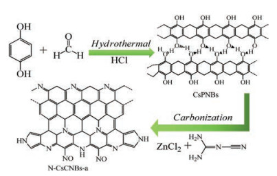
In this work, we designed a novel strategy to synthesis clewslike nitrogen doped hierarchical carbon materials through hydrothermal polymerization method and followed by carbonization. The carbonization, nitrogen doping and activation are integrated into one procedure. During this procedure, dicyandiamide (DCD) was used as nitrogen source, and ZnCl2 was used as an activator to increase the specific surface area. Finally, the obtained sample possesses hierarchical structure. Specifically, the micropores come from the carbonization of polymer and the chemical activation with the ZnCl2 treatment. For the mesopores, on the one hand, they are created from the original micropores widen by ZnCl2. On the other hand, new mesopores are also produced from the reaction between dicyandiamide and clews-like polymer. The macropores are formed from the intertwined nanobelts. This method realizes simple method preparation of nitrogen doped hierarchical porous carbon material, with the advantages of short reaction time and not using any template. Based on the above discussion, given high specific surface area, hierarchical porous structure and nitrogen doping, the N-doped carbon material has a high specific capacity and good rate performance.
The schematic diagram of the formation of N-CsCNBs-a is shown in Scheme 1. In short, firstly, clews-like polymer nanobelts, CsPNBs, are prepared by a simple hydrothermal polymerization method between hydroquinone and formaldehyde under acid catalysis environment. Subsequently, CsPNBs can be directly converted into CsCNBs through thermal carbonization at high temperature. During the carbonization process, in order to increase the specific surface area and introduce nitrogen atom into the carbon, ZnCl2 is used as the activator and DCD is also added and as nitrogen source for nitrogen doping. Fig. S1 (Supporting information) shows the SEM image of CsPNBs. The SEM image reveals that the polymerization products, CsPNBs, demonstrate clews-like with assembled of continuous and intertwisted nanobelts. More interesting, according to literature survey, sphere structure products are obtained when using phenol or catechol and formaldehyde. Nevertheless, the as-obtained products in this work exhibit nanobelts structure. The reason for this result is mainly attributed to the polymerization rate along the macromolecular chain axis is higher than that along the orthogonal direction [24, 25]. Furthermore, the hydrogen bonds between the polymer chains are also play an important role in the formation of the carbon nanobelts.

|
Download:
|
| Scheme 1. Schematic illustration of the synthesis procedure of N-CsCNBs-a. | |
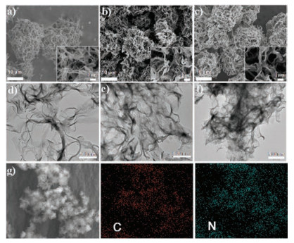
The morphologies of CsCNBs, CsCNBs-a and N-CsCNBs-a are shown in Figs. 1a–c, respectively. Interestingly, compared with the CsPNBs, the clews-like structure is still well retained, no matter direct thermal carbonization or carbonization accompany with the nitrogen doping and activation process. It is apparent that CsCNBs remain demonstrate clews-like and nanobelts are intertwined with each other. The size of CsCNBs is about 20–30 μm. However, from the zoom-in SEM images (Figs. 1a-c inset), we can see that there is a little bit difference in that the width of nanobelt of CsCNBs-a and N-CsCNBs-a becomes wider, which may be due to that polymer nanobelt could melt with each other during activation process at high temperature. Fig. 1d shows the TEM image of CsCNBs. Notably, the nanobelt of CsCNBs is thin and flexible. However, when add the activator during the carbonization process, the obtained nanobelts of CsCNBs-a are piled with each other and become thicker and wider (Fig. 1e). When both dicyandiamide and ZnCl2 are added, the nanobelts of the obtained samples, N-CsCNBs-a, become even wider and thicker (Fig. 1f), which is consistent with SEM observation. If examined closely (Fig. S2 in Supporting information), the piled nanobelts of NCsCNBs-a are full of pores because of the activation treatment. Fig. 1g shows the elemental mapping images of N-CsCNBs-a. It can be observed that C and N species are uniformly distributed in the matrix, which confirms that nitrogen atoms successfully doped into the carbon materials.

|
Download:
|
| Fig. 1. SEM images of (a) CsCNBs, (b) CsCNBs-a and (c) N-CsCNBs-a. The inset is the enlarged local image. TEM images of (d) CsCNBs, (e) CsCNBs-a and (f) N-CsCNBs-a. (g) The element mapping images of N-CsCNBs-a. | |
To further confirm the phases of all products including CsCNBs, CsCNBs-a and N-CsCNBs-a, XRD analysis was carried out. As shown in Fig. 2a, all samples exhibit a strong and broad peak at about 24° and a weak peak at about 43°, which corresponding to the (002) and (100) facet of graphitic carbon, respectively. Fig. 2b shows the Raman spectra of CsCNBs, CsCNBs-102 and CsCNBs-112. All samples demonstrate two distinct peaks: D-band (1350 cm-1) and G-band (1580 cm-1). What is more, it can be calculated that the intensity ratio of G band to D band of CsCNBs, CsCNBs-a and the N-CsCNBs-a is 1.02, 0.96 and 0.93, respectively. This indicates that the graphitization degree has decreased after activation and nitrogen doping. This may be because the activation process and nitrogen doping could induce the edge defects on the carbon surface, which results in the incensement of the intensity of D band [26, 27]. X-ray photoelectron spectroscopy (XPS) analysis shows that the N-CsCNBs-a has the elemental composition: C, O and N in the survey spectrum (Fig. 2c). No other peaks can be detected, indicating the high purity of the obtained carbon materials. The contents of carbon, nitrogen and oxygen in the N-CsCNBs-a are 85.02%, 10.58% and 4.4%, respectively. The high resolution N 1s spectrum (Fig. 2d) of N-CsCNBs-a could be deconvoluted into four peaks at 398.3, 400.5, 401.3 and 404.0 eV, which are ascribed to pyridinic nitrogen, pyrrolic nitrogen, quaternary nitrogen and oxidized nitrogen, respectively, further indicating that N atom is successfully merged into the carbon network matrix [28, 29]. In particular, pyridinic nitrogen atoms, as electrochemically active sites, can enhance surface-induced pseudocapacitance processes [30, 31].

|
Download:
|
| Fig. 2. (a) XRD patterns of CsCNBs, CsCNBs-a and N-CsCNBs-a. (b) Raman spectra of CsCNBs, CsCNBs-a and N-CsCNBs-a. (c) The XPS survey spectrum of N-CsCNBs-a. (d) N 1s spectrum with deconvoluted peaks of N-CsCNBs-a. | |
Nitrogen adsorption-desorption isotherms were performed to determine the specific surface area and pore size distribution of samples. As depicted in Fig. 3a, all the samples demonstrate the typical Ⅳ isotherm with a hysteresis loop, implying the existence of mesopores.Clearly, the hysteresisloops of N-CsCNBs-aarelarger than that of CsCNBs and CsCNBs-a, indicating much more mesopores are formed after activation and nitrogen doping. Furthermore, the initial adsorptions of N-CsCNBs-a and CsCNBsa arealso higher than thatof CsCNBs, demonstratingthat abundant micropores are generated through ZnCl2 activation. The related pore properties of the obtained samples are summarized in Table S1 (Supporting information). The specific Brunauer-EμmettTeller (BET) surface areasof the activatedsamples, N-CsCNBs-a and CsCNBs-a, are calculated to be 815m2/g and 1413m2/g, respectively, which are larger than that of non-activated sample, CsCNBs (508m2/g). Furthermore, the reason of the specific surface area of N-CsCNBs-a lower than that of CsCNBs-a should be attributed to the inability of N2 molecules to enter micropores blocked by nitrogen-containing functional groups [32]. Fig. 3b presents the pore size distribution (PSD) curves for N-CsCNBs-a based on the nonlocal density functional theory model. The CsCNBs-a shows more micropores, and the N-CsCNBs-a shows more small mesopores. It is also found that the pore volume of CsCNBs-a (1.1 cm3/g) and N-CsCNBs-a (0.84 cm3/g) is larger than that of CsCNBs (0.47 cm3/g). With the help of ZnCl2 activation process, new micropores are created and the mesopores are widened, resulting in higher specific surface area and total pore volume.

|
Download:
|
| Fig. 3. (a) Nitrogen adsorption-desorption isotherms and (b) the corresponding pore size distribution curves of CsCNBs, CsCNBs-a and N-CsCNBs-a. | |
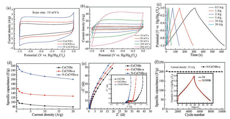
In order to evaluate the potential application of the clews-like carbon materials, all the samples were prepared into electrodes and evaluated by electrochemical performances. As shown in Fig. 4a, cyclic voltaμmetry (CV) is performed from -1V to 0V at a scanning rate of 10mV/s for CsCNBs, CsCNBs-a and N-CsCNBs-a electrodes. Compared with the CV curves of CsCNBs and CsCNBs-a electrode, it is obvious that the CV curve of N-CsCNBs-a electrode demonstrates rectangle like shape along with a broad hump, between -0.8V and 0V, indicating the coexistence of EDLC and pseudocapacitance. Furthermore, the CV integrated area of NCsCNBs-a electrode is greatly increased after nitrogen doping, which indicates that the specific capacity is greatly increased. It is reported that the doped nitrogen, especially pyridinic N species, can generate pseudocapacitance in alkaline electrolytes [31-33]. Thus, the specific capacitance of N-CsCNBs-a electrode is increased. Fig. 4b shows the CV curves of N-CsCNBs-a electrode at different scan rates. Encouragingly, it is noteworthy that the rectangular like CV curves can still be remained when the scan rate increases from 10mV/s to 200mV/s, which is indicative of the excellent rate capability performance.

|
Download:
|
| Fig. 4. (a) CV curves of CsCNBs, CsCNBs-a and N-CsCNBs-a electrodes at a scan rate of 10mV/s. (b) CV curves at different scan rates for N-CsCNBs-a electrode. (c) GCD curves at different current density for N-CsCNBs-a electrode. (d) Specific capacitance plots of CsCNBs, CsCNBs-a and N-CsCNBs-a electrodes as a function of different current densities. (e) Nyquist plots of CsCNBs, CsCNBs-a and N-CsCNBs-a electrodes. The inset is locally enlarged Nyquist plots. (f) Cycling stability of N-CsCNBs-a electrode at 10A/g. The inset shows the GCD curves before and after 10, 000 cycles. | |
Fig. 4c exhibits the galvanostatic charge-discharge curves of NCsCNBs-a electrode at different current densities. The curves are nearly linear with triangular shapes, suggesting the good capacitive characteristics and an excellent Coulombic efficiency [34]. When the current density gradually increases, the GCD curve still maintains a good axisyμmetric structure and the total charge-discharge time shrinks in equal proportion, due to diffusion-limited charge and discharge processes as well as the electrode overpotential at high current densities [35]. According to the formulation of C = It/mΔV, where C (F/g) is the specific capacitance, I (A) is the current, t (s) is the discharge time, ΔV (V) is the charge-discharge potential range, and m (g) is the mass of active materials. Fig. 4d shows the plots of specific capacitances vs. current densities of different electrodes. It can be calculated that the specific capacitance of N-CsCNBs-a electrode is 258F/g at the current density of 0.5A/g, which is far higher than that of CsCNBs electrode (107F/g) and CsCNBs-a electrode (160 F/g). When the current density increases to 20A/g, the specific capacitance of NCsCNBs-112 can still deliver a large specific capacitance of 203F/g, which is 79% of the initial capacitance taking that at 0.5 A/g as the basis. In addition, the specific capacitance of N-CsCNBs-a electrode is comparable or much higher than other nitrogen-doping porous carbon electrode materials reported in literature (Table S2 in Supporting information). The excellent rate performance of NCsCNBs-a electrode may be attributed to the role of nitrogen doping and hierarchical porous structure. On the one hand, the doped nitrogen atom enhances the electrical conductivity of carbon materials, which reduce the charge transfer resistance. On the other hand, the wettability of carbon materials also is improved, which facilitates the electrolyte contact with the activate materials. Moreover, the electrochemical impedance spectroscopy (EIS) tests are further performed to better understand the kinetic behavior of the electrodes. Fig. 4e shows the Nyquist plots of the prepared electrodes. It can be observed that all the curves possess a semicircle at high frequency and a straight line at the low frequency. Close inspection of these curves, NCsCNBs-a electrode shows the smallest semicircle and the steepest straight line, indicating the lowest electronic resistance and electrolyte distribution resistance. We speculate that the low resistance may be attributed to the hierarchical porous structure and excellent conductivity of the N-CsCNBs-a electrode [36, 37]. The large surface area, porous structure and improved conductivity are beneficial to charge transmission and electrolyte ions efficient diffusion.
Cycling stability is an important premise for the practical application of supercapacitor. To test this feature of N-CsCNBs-a electrode, it was run for 10, 000 charge-discharge cycles at 10 A/g current density, and the results are displayed in Fig. 4f. The result shows that N-CsCNBs-a electrode still delivers a high specific capacity of 201 F/g after 10, 000 cycles with 98.3% capacity retention. Moreover, the inset shows GCD curves of the NCsCNBs-a electrode before and after 10, 000 charge-discharge cycles, it can be concluded from the lining graph that the GCD curve of the N-CsCNBs-a electrode almost coincides with the first cycle after 10, 000 cycles, which further strongly verified that the N-CsCNBs-a electrode has a good cycling stability.
In summary, a simple hydrothermal combined with carbonization and activation method was used to prepare nitrogen-doped clews like carbon materials. The obtained hierarchical N-CsCNBs-a provides abundant channels for electrolyte transport and nitrogen active sites for redox reaction. Benefiting from this structure feature, as the electrode for supercapacitor, N-CsCNBs-a electrode has a high specific capacitance, 258 F/g at a current density of 0.5 A/g, and it still has 203 F/g at a high current density of 20 A/g. After 10, 000 charge-discharge cycles at 10 A/g, the specific capacitance was still maintained at 201 F/g, and the capacity retention is 98.3%. These results suggest that N-CsCNBs could be potentially used as a supercapacitor electrode, and other various applications.
AcknowledgmentsThis work was supported by the National Natural Science Foundation of China (No. 51802122), the Natural Science Fund of Hubei Province (No. 2017CFB155), China Scholarship Council (No. 201808420401), Scientific Research Plan Project of Hubei Education Department (No. B2017269), Scientific Research Initial funding for the Advanced Talent of Jianghan University (No. 1009-06810001), Opening Project of Key Laboratory of Optoelectronic Chemical Materials and Devices, Ministry of Education, Jianghan University (Nos. JDGD-201702, JDGD-201811) and Hubei Provincial Department of Education for the "Chutian Scholar" program.
Appendix A. Supplementary dataSupplementary data associated with this article can be found, in the online version, at https://doi.org/10.1016/j.cclet.2018.11.003.
| [1] |
R. Dai, W. Sun, Y. Wang, Electrochim. Acta 217 (2016) 123-131. DOI:10.1016/j.electacta.2016.08.051 |
| [2] |
M. Xie, S. Duan, Y. Shen, et al., ACS Energy Lett. 1 (2016) 814-819. DOI:10.1021/acsenergylett.6b00258 |
| [3] |
C. Long, L. Jiang, X. Wu, et al., Carbon 93 (2015) 412-420. DOI:10.1016/j.carbon.2015.05.040 |
| [4] |
K. Xiang, Z. Xu, T. Qu, et al., Chem. Commun. 53 (2017) 12410-12413. DOI:10.1039/C7CC07515D |
| [5] |
M. Xie, Z. Xu, S. Duan, et al., Nano Res. 11 (2018) 216-224. DOI:10.1007/s12274-017-1621-4 |
| [6] |
Z.F. Tian, M.J. Xie, Y. Shen, et al., Chin. Chem. Lett. 28 (2017) 863-867. DOI:10.1016/j.cclet.2016.12.004 |
| [7] |
M. Sevilla, R. Mokaya, Energy Environ. Sci. 7 (2014) 1250-1280. DOI:10.1039/C3EE43525C |
| [8] |
J. Liang, T. Qu, X. Kun, et al., Appl. Surf. Sci. 436 (2018) 934-940. DOI:10.1016/j.apsusc.2017.12.142 |
| [9] |
J. Tian, C. Cui, C. Zheng, W. Qian, Chin. Chem. Lett. 29 (2018) 599-602. DOI:10.1016/j.cclet.2018.01.027 |
| [10] |
J. Wei, D. Zhou, Z. Sun, et al., Adv. Funct. Mater. 23 (2013) 2322-2328. DOI:10.1002/adfm.201202764 |
| [11] |
W.J. Lu, S.Z. Huang, L. Miao, et al., Chin. Chem. Lett. 28 (2017) 1324-1329. DOI:10.1016/j.cclet.2017.04.007 |
| [12] |
B. Li, F. Dai, Q. Xiao, et al., Energy Environ. Sci. 9 (2015) 102-106. |
| [13] |
Y. Zhang, T. Qu, K. Xing, et al., J. Mater. Chem. A 6 (2018) 2353-2359. DOI:10.1039/C7TA09644E |
| [14] |
Z.S. Wu, K. Parvez, A. Winter, et al., Adv. Mater. 26 (2014) 4552-4558. DOI:10.1002/adma.v26.26 |
| [15] |
T.C. Chou, R.A. Doong, C.C. Hu, et al., ChemSusChem 7 (2014) 841-847. DOI:10.1002/cssc.201301014 |
| [16] |
L. Xie, G. Sun, F. Su, et al., J. Mater. Chem. A 4 (2016) 1637-1646. DOI:10.1039/C5TA09043A |
| [17] |
Q. Wang, J. Yan, Y. Wang, et al., Carbon 67 (2014) 119-127. DOI:10.1016/j.carbon.2013.09.070 |
| [18] |
J. Zhou, Z. Zhang, W. Xing, et al., Electrochim. Acta 153 (2015) 68-75. DOI:10.1016/j.electacta.2014.11.075 |
| [19] |
J. Liang, J. Zhao, Y. Li, et al., J. Taiwan Inst. Chem. E 81 (2017) 383-390. DOI:10.1016/j.jtice.2017.10.001 |
| [20] |
S.S. Yang, M.J. Xie, Y. Shen, et al., Chin. Chem. Lett. 27 (2016) 507-510. DOI:10.1016/j.cclet.2016.01.058 |
| [21] |
Z. Lyu, D. Xu, L. Yang, et al., Nano Energy 12 (2015) 657-665. DOI:10.1016/j.nanoen.2015.01.033 |
| [22] |
X. Zhang, L. Ma, M.Y. Gan, et al., J. Power Sources 304 (2017) 22-31. |
| [23] |
H. Peng, J. Liang, L. Zhu, et al., ACS Nano 8 (2014) 11280-11289. DOI:10.1021/nn503985s |
| [24] |
S. Zeng, N. Jin, H. Zhang, et al., RSC Adv. 4 (2014) 18676-18682. DOI:10.1039/C4RA01313A |
| [25] |
S. Zeng, X. Zeng, W. Tu, et al., J. Mater. Chem. A 5 (2017) 23209-23220. DOI:10.1039/C7TA08520F |
| [26] |
W.D. Oh, G. Lisak, R.D. Webster, et al., Appl. Catal. B:Environ. 233 (2018) 120-129. DOI:10.1016/j.apcatb.2018.03.106 |
| [27] |
J. Zhao, C. Liu, H. Deng, et al., Mater. Today Energy 8 (2018) 134-142. DOI:10.1016/j.mtener.2018.03.007 |
| [28] |
Z. Lin, G. Waller, Y. Liu, et al., Adv. Energy Mater. 2 (2012) 884-888. DOI:10.1002/aenm.201200038 |
| [29] |
D. Xie, X. Xia, Y. Zhong, et al., Adv. Energy Mater. 7 (2017) 1601804. DOI:10.1002/aenm.201601804 |
| [30] |
K. Mi, S. Chen, B. Xi, et al., Adv. Funct. Mater. 27 (2017) 1604265. DOI:10.1002/adfm.v27.1 |
| [31] |
J. Yang, Z. Ju, Y. Jiang, et al., Adv. Mater. 30 (2018) 1700104. DOI:10.1002/adma.v30.4 |
| [32] |
Y. Li, Z. Wang, L. Lin, et al., Carbon 99 (2016) 556-563. DOI:10.1016/j.carbon.2015.12.066 |
| [33] |
L. Lai, Y. Zhao, S. Ying, et al., RSC Adv. 8 (2018) 18714-18722. DOI:10.1039/C8RA02110D |
| [34] |
Y. Zhang, F. Wang, H. Zhu, et al., Appl. Surf. Sci. 426 (2017) 99-106. DOI:10.1016/j.apsusc.2017.07.127 |
| [35] |
W. Xing, S. Qiao, R. Ding, et al., Carbon 44 (2006) 216-224. DOI:10.1016/j.carbon.2005.07.029 |
| [36] |
J.Y. Liang, C.C. Wang, S.Y. Lu, J. Mater. Chem. A 3 (2015) 24453-24462. DOI:10.1039/C5TA08007J |
| [37] |
M. Xie, J. Yang, J. Liang, X. Guo, W. Ding, Carbon 77 (2014) 215-225. DOI:10.1016/j.carbon.2014.05.024 |