 2019, Vol. 30


b Key Laboratory of Materials-Oriented Chemical Engineering of Xijiang Uygur Autonomous Region, Shihezi 832003, China;
c Engineering Research Center of Materials-Oriented Chemical Engineering of Xinjiang Production and Construction Corps, Shihezi 832003, China;
d Collaborative Innovation Center of Renewable Energy Materials, Guangxi University, Nanning 530004, China
The cathodic oxygen reduction reaction (ORR) is a pivotal electrochemical process for energy conversion and storage systems, such as fuel cell and metal-air batteries [1-4]. Platinum (Pt) and its alloys are well known catalysts with superior catalytic activity for ORRs. However, the application of Pt-based materials has hampered the development and commercialization of fuel cells and metal-air batteries due to their high cost, low stability, and problems with methanol crossover among other reasons [5-9]. Therefore, it is important to design and synthesize advanced materials to replace Pt-based electrochemical catalysts for boosting ORRs [10-12].
Transitionmetals(Fe, Co, Mn, etc.) [13-17] and theiroxides [18-20] combining with nitrogen-doped (N-doped) carbon materials to create a class of catalysts has attracted increasing interest as ideal alternatives to Pt-based catalysts for ORRs. They are low cost, easily prepared, and demonstrate unprecedented catalytic efficiency. Recently, it has been largely reported that Co and its compounds coupled with N-doped carbon materials displayed excellent electrocatalytic activity toward ORRs. Among these Co-based composites combined with different N-doped carbon materials, it was reported that Co/NC [21], Co@MCM [22], Co/CoO/N-C [23], Co/ CoO-NGA [24], Co/Co3O4/N-C-750 ℃ [25] and Co3O4/Co-NPC [26] had been prepared as potential catalysts for ORRs. To the best of our knowledge, however, no reports have examined Co, CoO and Co3O4 coupled with the N-doped carbon materials as catalysts for ORRs.
Herein, we employed a partial oxidation strategy for the fabrication of Co, CoO and Co3O4 (Co-CoOx/N-C (SBM)) by modifying a nitrogen-doped composite of graphene and CNTs by using a facile sand-bath method (SBM). In the process, Co-CoO was successfully transferred into Co-CoOx during the prolysis, and the product was named Co-CoOx/N-C (SBM). This product presented an impressive onset potential of 0.91 V vs. RHE and a high limiting current density of 5.47 mA/cm2 in an alkaline solution. These values were close to the performance of commercial 20 wt% Pt/C (0.92 V vs. RHE, and 5.61 mA/cm2). The mid-wave potential of the product was also more positive than that of Pt/C. Notably, Co-CoOx/ N-C (SBM) demonstrated more activity than that of Co-CoO/N-C (CHT), which was synthesized by using a tube furnace under an argon atmosphere. Co3O4 belongs to the spinel group and has long been recognized as an active and stable catalyst for oxygen evolution and reduction in alkaline media, depending on the valences of the metallic cations. This may help explain why Co-CoOx/N-C (SBM) displayed outstanding catalytic performance towards ORRs [27].
Co-CoOx/N-C (SBM) was synthesized via a slow oxidation procedure. In a typical synthesis, 10 g of melamine, 1 g of starch and 0.5 g of Co(NO3)2 were mixed uniformly after grinding in a mortar, then the mixture was transferred to a 50 mL crucible and buried with certain sand and calcined at 550 ℃ for 2 h to produce g-C3N4 and then prolysized at 900 ℃ (5 ℃/min) for another 2 h in a Muffle Furnace to finally produce Co-CoOx/N-C (SBM). An additional Co-CoO/N-C (CHT) product was synthesized using the same amounts of melamine, starch and Co(NO3)2 under an argon atmosphere in a tube furnace for the final production.
X-ray diffraction (XRD) measurements were conducted with a Bruker D8 Advance X-ray diffraction using a Cu Kα 0.154 nm radiation source. X-ray photoelectron spectroscopy (XPS) was recorded using an Escalab 250Xi electron spectrometer. The nitrogen adsorption-desorption isotherm was measured using a Micromeritics ASAP 2020 HD88 BET instrument at -196 ℃. The specific surface area was calculated using the Brunauer-EmmettTeller (BET) multipoint method, and the pore volume and pore size distribution were determined by the Barrett-Joyner-Halenda (BJH) method. Transmission electron microscopy (TEM) and highresolution transmission electron microscopy (HRTEM) images were collected with a JEM-2100 (JEOL, Japan) instrument and Tecnai G2 F20 (FEI, USA) instrument, respectively. Raman spectroscopy data were collected from a Renishaw instrument with an Ar ion laser excitation of 514.5 nm.
The synthesized product (5 mg), 5 wt% Nafion solution (25 μL) and ethanol (475 μL) were mixed uniformly via ultrasonication (30 min) to form a catalytic ink. This catalytic ink (10 μL) was then dropped onto a glassy carbon electrode (3 mm diameter) and dried in air to serve as the working electrode. The electrochemical performance of the samples were examined using a CHI760D electrochemical station. An Ag/AgCl (in saturated KCl solution) reference electrode and Pt foil counter electrode were used as the other electrodes in the system. All experiments were carried out in a 0.1 mol/L KOH solution. Cyclic voltammetry (CV) curves were recorded from 0.2 V to -0.8 V. The polarization curves for the ORRs were acquired using a rotating disc electrode (RDE) with different rotation speeds. In a typical ORR procedure, the electron transfer numbers could be evaluated based on the slopes of the KouteckyLevich (K-L) plots using the following equation:
|
(1) |
where, J is the measured current density, Jk is the kinetic current density, ω denotes the electrode rotation speed, and B is calculated using the equation:

|
(2) |
where n is the electron transfer number per O2 molecule in the ORR procedure, F is the Faraday constant (96485 C/mol), C0 is the dissolved O2 concentration (1.2 ×10⁻³ mol/L), D0 is the O2 diffusion coefficient (1.9 ×10⁻⁵ cm2/s), and ν is the electrolyte kinematic viscosity (0.01 cm2/s).
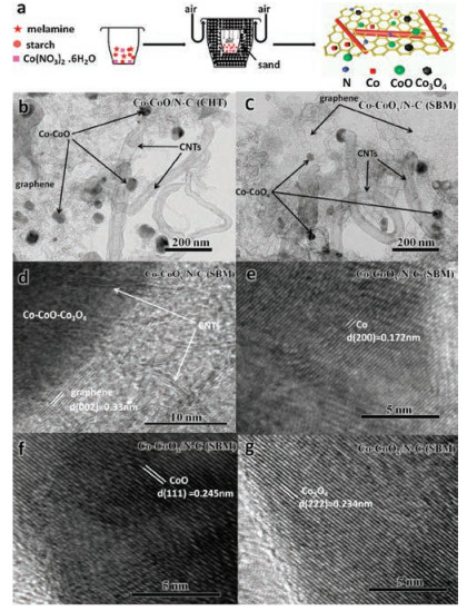
Fig. 1a illustrates the synthetic route of Co-CoOx/N-C (SBM) via SBM. In the typical process, melamine, starch and Co(NO3)2·6H2O were ground uniformly in a mortar, and then were put into a 50-mL crucible, which was buried into a 150-mL crucible using enough sand. Then, the 150-mL crucible was treated in Muffle furnace at 550 ℃ for 2 h to translate melamine into the sacrificial template (g-C3N4). As the temperature increased, starch transformed into graphene-like carbon, sacrificing the g-C3N4 when the temperature exceeded700 ℃. Co(NO3)2 acted as a catalyst to transformmelamine into CNTs. The resulting Co-CoO was then partially oxidized into Co-CoOx due to the entrance of air into the reaction system.

|
Download:
|
| Fig. 1. (a) The synthesis of Co-CoOx/N-C (SBM) via the sand-bath method. (b) TEM image for Co-CoO/N-C (CHT), (c) TEM image for Co-CoOx/N-C (SBM) and (d–g) HRTEM images for Co-CoOx/N-C (SBM). | |
Transmission electron microscopy (TEM) was performed to examine the morphology and structure of Co-CoO/N-C (CHT) and Co-CoOx/N-C (SBM). TEM confirmed the structure of Co-CoO/N-C (CHT) (Fig. 1b), which was comprised of Co-CoO, graphene and CNTs. The morphologies of Co-CoOx/N-C (SBM) (Fig. 1c) contained Co-CoOx, graphene and CNTs, suggesting that the morphology and structure of Co-CoOx/N-C (SBM) prepared via SBM was comparable to those of Co-CoO/N-C (CHT) prepared by CHT. In recent reports, melamine was able to produce g-C3N4, which served as a sacrificial template to prepare N-doped graphene [28, 29]. Melamine can also form bamboo-like CNTs when catalyzed by Fe or Co [30, 31]. Thus, melamine is a practical choice as a starting material to produce N-doped composites of graphene and CNTs.
High-resolution transmission electron microscopy (HRTEM) was performed to further investigate the structure of Co-CoOx/N-C (SBM). The HRTEM image (Fig. 1c) revealed a clear graphitic lattice structure with 0.33 nm spacing and a clear depiction of the CNTs in Co-CoOx/N-C (SBM). The HRTEM images (Figs. 1d, f and g) also displayed distinct lattice distances of 0.172 nm, 0.245 nm and 0.234 nm, which were indexed to the (200) plane of Co, (111) plane of CoO and (222) plane of Co3O4, respectively, suggesting that Co, CoO and Co3O4 were present in Co-CoOx/N-C (SBM).
X-ray diffraction (XRD) analysis was performed to determine the metal and carbon crystalline structure for Co-CoO/N-C (CHT) and Co-CoOx/N-C (SBM). As shown in Fig. 2a, in the XRD patterns of the two samples displayed three characteristic peaks at two theta values of 44.2°, 51.5°, and 75.8°, corresponding to the (111), (200), and (220) crystal planes of the Co phases (PDF#15-0806), respectively. Notably, the Co-CoO/N-C (CHT) and Co-CoOx/N-C (SBM) product samples displayed a set of tiny peaks at 26.5°, 42.4°, 61.5°, 73.7° and 77.5°, attributed to CoO (PDF#43-1004). Furthermore, the prominent diffraction peaks indexed to Co3O4 (PDF#43-1003) appeared in Co-CoOx/N-C (SBM) but were absent in Co-CoO/N-C (CHT), suggesting that introducting oxygen into the reaction system affected the Co composites during the gradual oxygenation process via SBM. Furthermore, Fig. 2a revealed a diffraction peak centered at ~26.5° for both product samples that could be attributed to the (002) plane of the graphitic carbon. However, Co-CoOx/N-C (SBM) displayed a narrower and sharper C (002) peak with higher intensity, suggesting that the carbon in Co-CoOx/N-C (SBM) displayed a higher degree of graphitization than the carbon in Co-CoO/N-C (CHT) [32, 33]. Thus, the XRD results not only indicated that Co-CoOx/N-C (SBM) had a high degree graphitization, but also demonstrated that Co, CoO and Co3O4 were all present in Co-CoOx/N-C (SBM), but were not all present in Co-CoO/N-C (CHT).

|
Download:
|
| Fig. 2. (a) XRD patterns and (b) Raman spectra of Co-CoO/N-C (CHT) and Co-CoOx/N-C (SBM). High-resolution XPS spectra of (c) C 1s, (d) N 1s, (e) O 1s and (f) Co 2p for Co-CoO/ N-C (CHT) and Co-CoOx/N-C (SBM). | |
In addition, the typical Raman spectra of Co-CoO/N-C (CHT) and Co-CoOx/N-C (SBM) composites (Fig. 2b) exhibited two prominent D band (~1330 cm-1) and G band (~1580 cm-1) peaks. Generally, the D band represents the presence of defective graphitic structures or, disordered carbon, while the G band stands for the tangential vibration of the sp2–bond carbon atoms and the structure of crystalline graphite in the graphitic layers [34]. Additionally, The peak occurring at ~2700 cm-1 (D band) is an overtone of the disorder-induced D band and the other one which occur at ~2940 cm-1 is the more readily visible defectactivated G band [35].
Moreover, the relative intensity ratio of the D peak to the G peak (ID/IG) can be used to estimate the defect for carbon-based materials [36]. The intensity ratio of the D band to G band (ID/IG) of Co-CoOx/N-C (SBM) was 0.927, which was higher than that of Co-CoO/N-C (CHT) (ID/IG = 0.868), suggesting that oxygen entered the reaction system during the sand bath process, which could lead to the structural imperfections observed in Co-CoOx/N-C (SBM). It has been reoported that the presence of defects is able to tailor the electron charge distribution and modulate the local band structure to carbon materials, which can promote the electron transfer and decrease the reaction free energy towards ORRs [37].
X-ray photoelectron spectroscopic (XPS) measurements were conducted to probe the chemical state and elemental content on the surface of Co-CoOx/N-C (SBM) and Co-CoO/N-C (CHT). Fig. 2c exhibited that the C 1s spectrum for Co-CoOx/N-C (SBM) was deconvoluted into three peaks at 284.2 eV, 285.4 eV and 289.2 eV, due to the binding energies of C=C, C=N and O—C=O, respectively. These three peaks were also present in Co-CoO/N-C (CHT) at almost identical eV: C=C at 284.3 eV, C=N at 285.4 eV, and O—C=O at 289.2 eV. The binding energies of C=C in Co-CoOx/N-C (SBM) and C=C in Co-CoO/N-C (CHT) agreed with the value reported for sp2 C in graphite. Additionally, the presence of C=N in the two samples confirmed that sp2 C bonded to a nitrogen atom (285–287 eV). Therefore, the C 1s XPS results evidenced that the obtained samples possessed a high degree of graphite and N together with O heteroatoms doped into C matrices. Fig. 2d highlighted that the corresponding N 1s spectra of the two samples could be split into three different types at the binding energy of 403.9 eV (oxidic-N), 400.7 eV (pyrrolic-N) and 398.2 eV (pyridinc-N).
Examination of the oxygen peaks revealed that the O 1s XPS peaks of Co-CoOx/N-C (SBM) were split into three peaks at 533.2 eV, 531.1 eV and 529.6 eV, corresponding to the surface O (Osur), deficiency O (Odef) and lattice O (Olatt), respectively (Fig. 2e). These three oxygen surfaces (Osur, Odef, and Olatt) could be attributed to oxygen bound to Co in +2 and +3 oxidation states, respectively [38-40]. The broad O 1s spectrum of the Co-CoO/N-C (CHT) product sample could only be fitted into two peaks at 533.2 eV (Osur) and 531.3 eV (Odef) suggesting that Co in the sample that was exposed to oxygen was cobalt oxide (denoted as CoO).
The XPS spectra of Co-CoOx/N-C (SBM) and Co-CoO/N-C (CHT) showed peaks for Co 2p (Fig. 2f). Two distinct satellite peaks were observed at 802.2 eV and 786.3 eV in the spectra of the two samples, respectively. The Co 2p3/2 and 2p1/2 spectra of the Co-CoOx/N-C (SBM) showed two pairs of spin-orbit doublets at 779.5 eV (Co3+) and 781.0 eV (Co2+), together with 794.6 eV (Co3+) and 796.4 eV (Co2+), suggesting the coexistence of Co2+ and Co3+. Meanwhile, two other peaks were found at 778.4 eV and 793.5 eV, which were both attributed to zero-valent Co. In contrast to these results for Co-CoOx/N-C (SBM), the deconvoluted XPS spectrum of Co-CoO/N-C (CHT) for Co 2p3/2 and 2p1/2 exhibited two pair peaks for Co2+ (796.1 eV and 780.6 eV) and Co° (793.3 eV and 778.2 eV) without the presence of Co3+ peaks [23]. Together, the XPS results confirmed that partial oxidation was beneficial for the formation of a Co3O4 phase, which played a significant role in promoting the electrocatalytic activity.
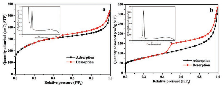
To further understand the ORR performance for the porous structures of the product samples, nitrogen adsorption-desorption isotherm measurements were conducted. As presented in Fig. 3, for the two samples, the nitrogen adsorption/desorption isotherms displayed an obvious hysteresis loop when the relative pressure (P/P0) was higher than 0.4, confirming that the mesopores were present in the two samples. Moreover, the inset figure in Fig. 3a confirmed that Co-CoO/N-C (CHT) possessed micropores, mesopores and macropores. However, mesopores and macropores were present in Co-CoOx/N-C (SBM), but micropores were absent.

|
Download:
|
| Fig. 3. Nitrogen adsorption-desorption isotherms and pore size distribution profiles (inset) of samples: (a) Co-CoO/N-C (CHT) and (b) Co-CoOx/N-C (SBM). | |
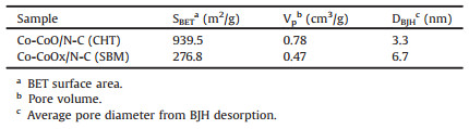
The textural properties of the two samples were listed in Table 1. As can be seen, Co-CoO/N-C (CHT) had a BET surface area of 939.5 m2/g, a pore volume of 0.78 cm3/g, and a mean pore diameter of 3.3 nm. Co-CoOx/N-C (SBM) had a surface area, pore volume, and average pore diameter of 276.8 m2/g, 0.47 cm3/g, and 6.7 nm, respectively. Co-CoOx/N-C (SBM) displayed a pronounced reduction in both surface area and pore volume relative to Co-CoO/N-C (CHT), but its average pore diameter was twice that of Co-CoO/N-C (CHT). Therefore, a larger average pore diameter might be more important for the enhancement of the performance of ORRs than the BET surface area and pore volume.
|
|
Table 1 Textual characteristics of Co-CoO/N-C (CHT) and Co-CoOx/N-C (SBM). |
To investigate the electrocatalytic performance of the Co-CoOx/ N-C (SBM) product sample for ORRs, cyclic voltammetry (CV) was carried out in a 0.1 mol/L nitrogen- or oxygen- saturated KOH solution. Fig. 3a showed that the CV for Co-CoOx/N-C (SBM) displayed a well-defined cathodic peak in the O2-saturated 0.1 mol/L KOH solution, however, this peak was absent in the N2- saturated solution, demonstrating that Co-CoOx/N-C (SBM) exhibited outstanding electrocatalytic activity toward ORRs. The ORR activities of Co-CoOx/N-C (SBM), Co-CoO/N-C (CHT) and 20 wt% Pt/ C were further investigated by linear sweep voltammetry (LSV) using a RDE with a rotating sweep rate of 1600 rpm. As shown in Fig. 3b, Co-CoO/N-C (CHT) displayed the worst ORR activity, with an onset potential (0.88 V vs. RHE), half-wave potential (0.82 V vs. RHE) and limited current density (5.0 mA/cm2) that were compared to those in the literatures (Table 1). In contrast, CoCoOx/N-C (SBM) displayed an ORR onset potential (0.91 V vs. RHE) that was close to that of Pt/C (0.92 V vs. RHE), with a mid-wave potential (0.85 V vs. RHE) higher than that of the 20 wt.% Pt/C (0.83 V vs. RHE), and a limited current density (5.46 mA/cm2) close to that of Pt/C (5.56 mA/cm2), suggesting that Co-CoOx/N-C (SBM) displayed an excellent electrocatalytic performance for ORRs (Table 2).
|
|
Table 2 Preparation processes of Co-CoOx/N-C (SBM) and other Co-based catalysts for electrocatalysis. |

The catalytic performance of Co-CoOx/N-C (SBM) for ORRs was further evaluated using linear sweep voltammetry (LSV) on a rotating disk electrode (RDE) in a O2-saturated 0.1 mol/L KOH electrolyte at various rotation rates (Fig. 4c). K-L plots were generated from the LSV plots of Co-CoOx/N-C (SBM) (Fig. 4c) and displayed a good linear relationship between the inverse current density (1/J) and the inverse of the square root of the rotation speed (1/ω1/2), suggesting first-order reaction kinetics with respect to the concentration of dissolved oxygen [41]. The average electron transfer number (n) of Co-CoOx/N-C (SBM) during the ORR process was calculated from the slope of the K-L plots based on Eq. (2). For Co-CoOx/N-C (SBM), Fig. 4d (the inset figure) showed that the average value of n within the potential from 0.25 V to 0.75 V was calculated to be 3.86, confirming that O2 reduction followed a four-electron pathway reaction.

|
Download:
|
| Fig. 4. (a) CV curves of Co-CoOx/N-C (SBM) in N2-saturated (black line) and O2-saturated (red line) 0.1 mol/L KOH electrolyte solutions at a scan rate of 50 mV/s, (b) LSV curves for Co-CoOx/N-C (SBM), Co-CoO/N-C (CHT) and 20% Pt/C in O2-saturated 0.1 mol/L KOH with a rotating speed of 1600 rpm, (c) LSV curves for oxygen reduction on Co-CoOx/N-C (SBM) at various rotation speeds, (d) K-L plots and the electron transfer numbers (inset) of Co-CoOx/N-C (SBM), (e) Long-term stability tests and (f) tolerance to alcohol poisoning of Co-CoOx/N-C (SBM) and Pt/C via the ORR cathodic current-time (i-t) method. (For interpretation of the references to colour in this figure legend, the reader is referred to the web version of this article). | |
Chronoamperometric measurements were also employed to determine the catalytic stability of Co-CoOx/N-C (SBM) (Fig. 4e). After continuous operation for 20, 000 s, the retention ratio of the current density for Co-CoOx/N-C (SBM) was ~79.4%, whereas there was ~52.6% loss for the Pt/C catalyst under the same condition. This indicated Co-CoOx/N-C (SBM) possessed an excellent durability, ascribed to the cooperation of the graphene and CNTs combined with Co-CoOx.
As well known, the methanol crossover of Pt-based catalysts seriously affects the fuel cell performance. Therefore, methanol crossover tests were performed with Co-CoOx/N-C (SBM) and the commercial Pt/C (20 wt%) in 0.1 mol/L KOH solutions under an oxygen atmosphere. Fig. 4f showed that the Co-CoOx/N-C (SBM) retained a higher relative current (~92.5%) compared to Pt/C (~50.9%) after 300 s upon injecting 3 mol/L methanol. These results indicated that Co-CoOx/N-C (SBM) was not only more stable, but also showed better selective activity towards ORRs than 20 wt% Pt/C.
In summary, we developed a facile method for the synthesisof the Co, CoO and Co3O4 composite catalysts for ORRs. The catalyst consisted of the spinel Co crystals and an N-doped composite of graphene and CNTs. The synthesis process was simple, achieved by prolysis of a mixture of starch, melamine and Co(NO3)2 using a sand bath in a Muffle furnace. Starch was the carbon precursor and Co (NO3)2 catalyzed the formation of the CNTs. Two products were formed by this general synthesis, with Co-CoOx/N-C (SBM) formed using the Muffle furnace and Co-CoO/N-C (CHT) formed using a tube furnace. Co-CoOx/N-C (SBM) exhibited a higher electrochemical catalytic ORR performance than the Co-CoO/N-C (CHT). The higher performance of Co-CoOx/N-C (SBM) may be due to the formation of Co3O4 during the synthesisprocess.Co-CoOx/N-C (SBM) also showed better durability and tolerance of methanol poisoning than the commercial 20 wt% Pt/C in alkaline solution, suggesting that it has potential as a high performance catalyst for ORRs. This research opens up a new protocol for the design and synthesis of metal and metal oxide alternative catalysts for fuel cells.
AcknowledgmentsThis work was supported by the National Natural Science Foundation of China (No. U1303291) and the Program for Changjiang Scholars and Innovative Research Team in University (No. IRT_15R46).
| [1] |
J. Suntivich, H.A. Gasteiger, N. Yabuuchi, H. Nakanishi, J.B. Goodenough, Nat. Chem. 3 (2011) 546-550. DOI:10.1038/nchem.1069 |
| [2] |
F. Cheng, J. Chen, Chem. Soc. Rev. 41 (2012) 2172-2192. DOI:10.1039/c1cs15228a |
| [3] |
H. Wei, X. Su, J. Liu, et al., Electrochem. commun. 88 (2018) 19-23. DOI:10.1016/j.elecom.2018.01.011 |
| [4] |
J. Wang, Z. Wu, L. Han, et al., Chin. Chem. Lett. 27 (2016) 597-601. DOI:10.1016/j.cclet.2016.03.011 |
| [5] |
D. Wang, D. Astruc, Chem. Soc. Rev. 46 (2017) 816-854. DOI:10.1039/C6CS00629A |
| [6] |
D. Yan, Y. Li, J. Huo, et al., Adv. Mater. 29 (2017) 1606459. DOI:10.1002/adma.v29.48 |
| [7] |
J. Xiao, Y. Xu, Y. Xia, J. Xi, S. Wang, Nano Energy 24 (2016) 121-129. DOI:10.1016/j.nanoen.2016.04.026 |
| [8] |
J. Xu, C. Xiao, S. Ding, Chin. Chem. Lett. 28 (2017) 748-754. DOI:10.1016/j.cclet.2016.12.006 |
| [9] |
L. Wang, W. Jia, X. Liu, et al., J. Energy Chem. 25 (2016) 566-570. DOI:10.1016/j.jechem.2016.02.012 |
| [10] |
Y. Wang, F. Yu, M. Zhu, et al., J. Mater. Chem. A 6 (2018) 2011-2017. DOI:10.1039/C7TA08607E |
| [11] |
Y. Wang, M. Zhu, Y. Li, et al., Green Energy Environ. 3 (2018) 172-178. DOI:10.1016/j.gee.2017.06.005 |
| [12] |
W. Zhang, Y. He, S. Zhang, et al., Electrochem. commun. 81 (2017) 34-37. DOI:10.1016/j.elecom.2017.05.021 |
| [13] |
W. Xia, A. Mahmood, Z.B. Liang, R.Q. Zou, S.J. Guo, Angew. Chem. Int. Ed. 55 (2016) 2650-2676. DOI:10.1002/anie.201504830 |
| [14] |
W. He, Y. Wang, C. Jiang, L. Lu, Chem. Soc. Rev. 45 (2016) 2396-2409. DOI:10.1039/C5CS00665A |
| [15] |
C. Zhu, H. Li, S. Fu, D. Du, Y. Lin, Chem. Soc. Rev. 45 (2016) 517-531. DOI:10.1039/C5CS00670H |
| [16] |
B. Bayatsarmadi, Y. Zheng, A. Vasileff, S. Qiao, Small 13 (2017) 1700191. DOI:10.1002/smll.v13.21 |
| [17] |
L. Hou, J. Guo, Z. Xiang, J. Energy Chem. 28 (2019) 73-78. DOI:10.1016/j.jechem.2018.01.010 |
| [18] |
K. Elumeeva, M.A. Kazakova, D.M. Morales, et al., ChemSusChem 11 (2018) 1204-1214. DOI:10.1002/cssc.v11.7 |
| [19] |
A.R. Mainar, L.C. Colmenares, O. Leonet, et al., Electrochim. Acta 217 (2016) 80-91. DOI:10.1016/j.electacta.2016.09.052 |
| [20] |
I.M. Mosa, S. Biswas, A.M. El-Sawy, et al., J. Mater. Chem. A 4 (2016) 620-631. DOI:10.1039/C5TA07878D |
| [21] |
B. Guan, L. Yu, X.W.D. Lou, Adv. Sci. 4 (2017) 1700247. DOI:10.1002/advs.201700247 |
| [22] |
H. Zhang, W. Zhou, T. Chen, et al., Energy Environ. Sci. 11 (2018) 1980-1984. DOI:10.1039/C8EE00901E |
| [23] |
H. Wang, W. Wang, M. Asif, et al., Nanoscale 9 (2017) 15534-15541. DOI:10.1039/C7NR05208A |
| [24] |
M. Wang, Y. Hou, R.C.T. Slade, et al., Front. Chem. 4 (2016) 36. |
| [25] |
Z. Wu, P. Chen, Q. Wu, et al., Nano Energy 8 (2014) 118-125. DOI:10.1016/j.nanoen.2014.05.019 |
| [26] |
T. Zhan, S. Lu, X. Liu, H. Teng, W. Hou, et al., Electrochim. Acta 265 (2018) 681-689. DOI:10.1016/j.electacta.2018.02.006 |
| [27] |
M. Hamdani, R.N. Singh, P. Chartier, C. Dakhla, A. Maroc, Int. J. Electrochem. Sci. 5 (2010) 556-577. |
| [28] |
X. Li, S. Kurasch, U. Kaiser, M. Antonietti, Angew. Chem. Int. Ed. 51 (2012) 9689-9692. DOI:10.1002/anie.v51.38 |
| [29] |
L. Tian, X. Wei, Q. Zhuang, Nanoscale 6 (2014) 6075-6083. DOI:10.1039/C4NR00454J |
| [30] |
W. Yang, X. Liu, X. Yue, J. Jia, S. Guo, J. Am. Chem. Soc. 137 (2015) 1436-1439. DOI:10.1021/ja5129132 |
| [31] |
G. Zhang, W. Lu, F. Cao, Z. Xiao, X. Zheng, J. Power Sources 302 (2016) 114-125. DOI:10.1016/j.jpowsour.2015.10.055 |
| [32] |
Y. Wang, M. Zhu, G. Wang, et al., Nanomaterials 7 (2017) 404. DOI:10.3390/nano7110404 |
| [33] |
L. Shi, T. Wu, Y. Wang, et al., Materials 10 (2017) 1030. DOI:10.3390/ma10091030 |
| [34] |
D.H. Seo, Z.J. Han, S. Kumar, K.K. Ostrikov, Adv. EnergyMater. 3 (2013) 1316-1323. |
| [35] |
R. Arsat, M. Breedon, M. Shafiei, et al., Chem. Phys. Lett. 467 (2009) 344-347. DOI:10.1016/j.cplett.2008.11.039 |
| [36] |
J. Zhu, K. Li, M. Xiao, et al., J. Mater. Chem. A 4 (2016) 7422-7429. DOI:10.1039/C6TA02419J |
| [37] |
J. Zhang, H. Zhou, J. Zhu, et al., ACS Appl.Mater. Interfaces 9 (2017) 24545-24554. DOI:10.1021/acsami.7b04665 |
| [38] |
M. Jayakumar, K. Hemalatha, A.A. Chander, A.K. Sahu, A.S. Prakash, Carbon 125 (2017) 168-179. DOI:10.1016/j.carbon.2017.09.002 |
| [39] |
J. Bao, X. Zhang, B. Fan, et al., Angew. Chem. Int. Ed. 54 (2015) 7399-7404. DOI:10.1002/anie.v54.25 |
| [40] |
S. Guo, S. Zhang, L. Wu, S. Sun, Angew. Chem. Int. Ed. 51 (2012) 11770-11773. DOI:10.1002/anie.201206152 |
| [41] |
S.H. Ahn, X. Yu, A. Manthiram, Adv. Mater. 29 (2017) 1606534. DOI:10.1002/adma.201606534 |