 2019, Vol. 30


b Analysis and Testing Center, South China Normal University, Guangzhou 510006, China;
c Institute of Bioengineering and Nanotechnology, Singapore 138669, Singapore
The energy-storage devices have attracted an ever-increasing research interest due to the worldwide environment issue and shortage of fossil energy. Among the various energy-storage devices, supercapacitors (SCs), exhibiting fast charging-discharging characteristics, high power density and large cycle life, have been provoked as highly promising candidates for use in electronic devices [1]. Supercapacitors can be categorized into two types depending on charge storage mechanisms. The first type is electrical double layer capacitors (EDLCs), which store electrochemical energy by ion adsorbing-disadsorbing. Carbon materials, such as activated carbon [2], CNT [3] and graphene, with high surface-area are usually utilized as EDLCs electrodes. The other type consists of pseudocapacitors, which mostly use transition metal oxides/hydroxide (NiO [4], MnO2 [5], Fe2O3[6], Co3O4[7], Co(OH)2[8] andNi(OH)2[9])and conducting polymers (PEDOT-PSS [10], polyaniline [11], etc.) as electrodes, where capacitance comes from fast redox reactions. In general, pseudocapacitors display higher capacitance, but inferior rate capability and cycling life than EDLCs [12], due to the semiconducting or insulating nature of most metal oxides/hydroxide [13]. Thus, new materials must be exploited to meet the growing demand of SCs for future applications.
Metal-organic frameworks (MOFs), emerging as a new class of materials with tunable porosity, wide varieties, large specific surface area and excellent physical and chemical properties, have attracted tremendous attention in recent years, with demonstrated applications in such as catalysis [14], gas storage [15], separation [16], sensors [17], water purification [18], lithium-ion batteries [19] and supercapacitors [20-23]. The pristine MOFs can be directly used as electrode materials for SCs, due to their porosity and metal cations that provide the accommodation space for electrolyte and the redox active sites, respectively [23]. Apart from direct use, MOFs have also served as sacrificial materials for synthesizing metal oxides [24-26], carbons [27] and composites [28] or as supports to load nanomaterials [29]. Díaz et al. firstly reported the utilization of pristine MOFs (Co8-MOF-5) as electrodes materials for electric double layer capacitors, which established the feasibility of MOFs-based electrodes [30]. Yaghi et al. synthesized a series of MOFs with different central metal ions and organic ligands for SCs [31]. It was found that zirconium-based MOFs displayed relatively high areal specific capacitance. Ma's group has synthesized a ball-in-cage (BIC) nanostructure material for SCs, possessing a capacitance of 119 F/g at a current density of 0.5 A/g [22]. A high capacitance of 726 F/g for Ni-MOF was recently reported by Kong et al. [32]. Nevertheless, studies on pristine bimetallic MOFs as electrode materials are still very rare [33]. The main reason could be due to the poor electrical conductivity of pristine MOFs, and we believe substituting the central metal with other ions might be a feasible approach to overcome this disadvantage [1, 21].
In this work, we provided a simple strategy to synthesize layered Co-doped Ni-MOF as an excellent electrode material for SCs. While the original crystalline topology of Ni3(BTC)2·12H2O still remains for the [Ni3-xCox(BTC)2·12H2O] (x ≈ 0.25, 0.5), the Ni/Co-MOF exhibited a specific capacitance of 1067 F/g at a discharge current density of 1 A/g, which is two times that for Ni-MOF. The good rate capability was obtained with a specific capacitance of 780 F/g at 10 A/g. These results suggest that bimetallic MOF could function as promising and innovative materials for supercapacitors.
All solvents and reagents for the syntheses were of analytical grade and were used as received from commercial sources without further purification. In a typical experimental set-up, 0.594 g of NiCl2·6H2O, 0.420 g of 1, 3, 5-benzenetricarboxylic acid (H3BTC) and different amounts of CoCl2·6H2O (0, 0.059, 0.118 g) were dissolved in a mixed DMF (N, N-dimethylformamide, 10 mL) and H2O (10 mL) solution with stirring at room temperature. Then, the mixture was transferred to a 50 mL Teflon-lined stainless steel autoclave and maintained at 120° for 24 h. After cooling down to room temperature, the precipitate was thoroughly washed several times with DMF and H2O, respectively. Finally, the Co-doped Ni-MOFs were dried at 60° for 12 h under vacuum condition. Herein, Codoped Ni-based MOF materials prepared with different amounts of CoCl2·6H2O (0, 0.059, 0.118 g) are denoted as Ni-MOF, Ni/Co-MOF-0.25 and Ni/Co-MOF-0.5, respectively.
The morphologies of samples were analyzed by using FESEM (ZESISS ULTRA 55, Germany) and transmission electron microscopy (TEM, JEOL JEM-2100HR, Japan). X-ray diffraction (XRD) patterns were obtained by XRD-6000 (Shimadzu) in the Bragg's angle (2θ) range from 5° to 50° with monochromatic Cu Kα radiation. Inductively coupled plasma (ICP) measurements (725 ICP-OES, Agilent) were used to determine the ions rate of Ni and Co. Fourier transform infrared (FTIR) analysis (Nicolet 6700) was conducted in the range of 400 cm-1 to 4000 cm-1. Thermogravimetric analysis was performed using Q500 under air conditions from room temperature to 780 ℃. The valence state of the samples was measured by X-ray photoelectron spectroscopy (XPS) using ESCALAB250Xi system (Thermo Fisher Scientific, USA) with an Al Kα (mono) irradiation.
A CHI 660E electrochemical workstation was used to perform the electrochemical properties of the samples with a threeelectrode system in 3 mol/L KOH aqueous electrolyte at room temperature. The working electrodes were prepared by mixing the active materials, carbon black and polyvinylidene difluoride (PVDF) in a weight ratio of 8:1:1. Then, an appropriate amount of N-methyl 2-pyrrolidone was added and grinded evenly to produce a slurry. The slurry was coated onto the pre-weighed nickel foam current collectors (1 cm × 1 cm) and dried in vacuum at 60 ℃ for 12 h to obtain the working electrode. The mass of the active material on nickel foam for Ni-MOF, Ni-Co-MOF-0.25 and Ni-Co-MOF-0.5 were 5.15, 4.96 and 6.09 mg, respectively. Platinum foil (1.5 cm × 1.5 cm) and a saturated calomel electrode were used as the counter and reference electrodes, respectively.
Cyclic voltammetry (CV) measurements were conducted at various scan rates from 5 to 50 mV/s in the potential window of 0- 0.5 V. Galvanostatic charge-discharge (GCD) measurements were carried out at different current densities form 1–20 A/g. The cycle performance was examined by GCD measurement at the current density of 10 A/g for 2500 cycles. Electrochemical impedance spectroscopy (EIS) was also measured. The amplitude of AC voltage is 5 mV and the frequency range is from 0.01 Hz to 100 kHz.
The specific capacitance of the electrode was calculated from the discharge curves according to the following equation:

|
where C is the specific capacitance in F/g, I is the discharge current in A, Δt is the time of discharge in s, m is mass of the active materials in g, and ΔV is the discharge voltage window in V.
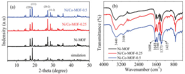
Fig. 1a shows the XRD patterns of the Ni-MOF and Ni/Co-MOF. All the patterns are in good agreement with that simulated from the single-crystal data of [Ni3(BTC)2·12H2O] (CCDC-1274034), four distinct diffraction peaks standing at 17.5°, 18.7°, 27.2° and 28.6° are indexed to the (220), (111), (20-2) and (11-2) planes, respectively. No impurity peaks were detected in the XRD results for the Ni/CoMOF, implying that the Co doping did not change the original NiMOF structure. The FTIR spectrum of samples are shown in Fig. 1b. All the peaks of samples are almost the same, which agree with the XRD results. The bands at 3440 cm-1 and 3108 cm-1 are due to the stretching vibration of water molecules, confirming the existence of coordinated H2O molecules within the structure. The strong absorption bands at 1648, 1606, 1546, 1435 and 1373 cm-1 were assigned to the asymmetric and symmetric stretching modes of the coordinated (-COO-) group, respectively [1, 34]. It should be noted that after doping of Co ions, the band at 1648 cm-1 appeared in Ni/ Co-MOFs, indicating the Co2+ ions doped in the MOFs have changed the surrounding environment of -COO- group. The absence of absorption bands from 1730 cm-1 to 1690 cm-1 associated with the -COOH is indicative of the deprotonation of H3BTC upon its contact with metal ions [35].

|
Download:
|
| Fig. 1. XRD patterns (a) and FTIR spectra (b) of Ni-MOF and Ni/Co-MOFs. | |
The SEM images of Ni/Co-MOFs are shown in Figs. S1a–c in Supporting information. It can been seen that all the samples exhibit a loosely packed layer structure, which is similar to the accordion-like Ni-MOF reported by Yan et al. [36]. The TEM images of the Ni-MOF, Ni/Co-MOF-0.25 and Ni/Co-MOF-0.5 are shown in Figs. S1(d, g), Figs. S1(e, h) and Figs. S1(f, i) in Supporting information, respectively. The layer structure existed in Ni-MOF and Ni/CoMOFs can be confirmed from Figs. S1(d–f). Meanwhile, it can be seen from Figs. S1(g–i) that the surface of all samples shows small pores. After doping the Co ions, the size of pores became smaller, which is about 5 nm, 2 nm and 4 nm for Ni-MOF, Ni/Co-MOF-0.25 and Ni/Co-MOF-0.5, respectively. The obtained nano-pores is comparable with the pore size of similar MOFs [33]. The hierarchical structure composed by the layer structure and smaller pores on the surface may increase the contact area between active materials and electrolyte, which results in a higher capacitance.
Schematic illustration of the synthetic process of MOFs is shown in Fig. 2a. The light green color of Ni-MOFs changes to brown after doping of Co ions, which confirms the Ni ions have been substituted by Co ions. Ball and stick views of Ni-MOF along c axis and b axis are shown in Figs. 2b and c. The structure of Ni-MOF is composed of zigzag chains constructed from two symmetryinequivalent tetra-aqua nickel(Ⅱ) units and BTC ligands, as shown in Fig. 2b. As shown in Fig. 2c, the zigzag chains can be reinforced and held together by numerous hydrogen bonding interactions involving every remaining water and carboxylate units in the structure to yield a tightly associated 3-D network [32].

|
Download:
|
| Fig. 2. Schematic illustration of the synthetic process of MOFs (a), and ball and stick view of Ni-MOF along c axis (b) and b axis (c). | |
TG curves of samples measured in air from room temperature to 790° are shown in Fig. S2 in Supporting information. Two stages of weight loss were observed during the whole test. It can be seen that the first weight loss up to 350° could be due to the loss of coordinated water molecules in channel. The primary weight loss of the MOFs appears at the second stage, which was attributed to the decomposition of the organic component starting at 393°, 380° and 366° for Ni-MOF, Ni/Co-MOF-0.25 and Ni/Co-MOF-0.5, respectively. The decrease of the decomposition temperature may be due to the structure defects caused by doping the Co ions.
XPS measurements were conducted to acquire further information on the chemical composition of Ni/Co-MOF-0.5 sample. Our results reveal a clear existence of C, O, Co and Ni elements (Fig. 3a). In the high-resolution Co 2p spectrum (Fig. 3b), two major peaks of Co 2p centered around 797.5 eV (Co 2p1/2) and 781.8 eV (Co 2p3/2) eV with a spin-energy separation of 15.7 eV indicate that the Co element existed in a divalent state [37]. As shown in Fig. 4c, the Ni 2p spectrum indicates that the Ni 2p3/2 and Ni 2p1/2 peaks are located at the binding energy of 856.3 and 873.8 eV accompanied by two satellite bands, respectively, implying the presence of Ni element in the form of a divalent state [38].

|
Download:
|
| Fig. 3. XPS spectrum of the Ni/Co-MOF-0.5 (a) and the elemental analysis of Co 2p (b) and Ni 2p (c). | |

|
Download:
|
| Fig. 4. CV curves of the Ni-MOF and Ni/Co-MOF at a scan rate of 5 mV/s (a); CV curves of Ni/Co-MOF-0.25 at the scan rate between 5 mV/s and 50 mV/s (b); Charge and discharge curves of Ni/Co-MOF-0.25 at different current densities (c); Specific capacity of three samples at various current densities (d); Cycling performance of three samples at a discharge current density of 10 A/g (e); Nyquist plots of three samples (the inset shows the equivalent electrical circuit from the fitted impedance spectra) (f). | |
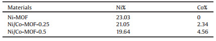
Ion distributions of Ni and Co determined by inductively couple plasma (ICP) elemental analysis are shown in Table 1. The ratios of Ni and Co in the Ni-MOFs, Ni/Co-MOF-0.25, Ni/Co-MOF-0.5 were 0.2303:0, 0.2105:0.0234 and 0.1964:0.0456, respectively, which confirm that the Ni2+ have been partially substituted by Co2+ in the Ni/Co-MOFs.
|
|
Table 1 Ion distributions of Ni and Co determined by ICP. |
To investigate the potential application as electrode materials, the electrochemical performance of synthesized MOFs was tested using a three-electrode system in 3 mol/L KOH aqueous electrolyte. CV curves of the Ni-MOF and Ni/Co-MOFs at a scan rate of 5 mV/s are shown in Fig. 4a. A pair of redox peaks was observed from 0 to 0.5 V, indicating typical pseudocapacitance characteristic of all samples, which is well distinguished from that of the electrical double-layer capacitors. The respective reduction and oxidation peaks might correspond to the intercalation and deintercalation of OH- during electrochemical reactions as similarly observed for Ni (OH)2 and Co(OH)2 [1, 37]. These indicate that the capacitance of Ni/ Co-MOFs might be mainly attributed to the combination of ion exchange and redox mechanism, which were on account of the redox pair of Ni - O/Ni - O-OH and Co-O/Co-O-OH corresponding to the deintercalation and intercalation of OH- [39]. This process might be represented by the following electron transfer equation:

|
Fig. 4b shows the CV curves of Ni/Co-MOF-0.25 at different scan rates between 5 mV/s and 50 mV/s. With the increase in scanning rate, the potential difference between anodic and cathodic peaks also increased, which can be attributed to the polarization effect of the electrode under a high scan rate [7]. Fig. 4c shows the charge and discharge curves of Ni/Co-MOF-0.25 at different current densities. The potential time response is nonlinear, displaying the characteristics of pseudocapacitance, which is consistent with the results of CV curves. The calculated specific capacitances of all samples as a function of the discharge current density are shown in Fig. 4d. The specific capacitances of Ni/Co-MOF-0.25 are much higher than that of Ni-MOF but only slightly higher than that of Ni/ Co-MOF-0.5, highlighting the significant synergistic effect of Ni and Co ions. In particular, Ni/Co-MOF-0.25 exhibits the highest capacitance, achieving 1067, 972, 870, 816 and 780 F/g, at current densities of 1, 2, 5, 8 and 10 A/g, respectively. The decrease of the capacitance value is due to the relatively insufficient faradic redox reaction at higher current densities. The results of cycle life tests at a constant current density of 10 A/g are shown in Fig. 4e. The Ni/Cobased MOFs displayed a slight decrease in retention rate, and retained 68.4% of the original capacitance (520 F/g) after the 2500 cycles, indicating that the Ni/Co based MOFs had an excellent cycling property. The reason for the capacity loss could be attributed to the decomposition of the layered structure during the intercalation and deintercalation of OH-, which can be confirmed from the images of Fig. S3 (Supporting information). Compared with the previously reported results for Ni-MOFs, CoMOFs, CoNiO, Co/Fe-MOF, ZnCo2O4 or Ni/Co(OH)2, our synthesized materials are comparable or even superior to them. The results of comparison are shown in Table 2.
|
|
Table 2 The results of comparison with previous reports. |

To gain further insight into the electrical conductivity of the Ni/Co-MOF, electrochemical impedance spectroscopy measurements were conducted. The inset of Fig. 4f shows the equivalent electrical circuit from the fitted impedance spectra, which consists of an electrolyte solution resistance (Rs), Warburg impedance (W), charge-transfer impedance(Rct), and a constant phase element [45]. It can be seen form Fig. 4f that a semicircle at the high frequency and a straight line at the low frequency region are shown, which represents the charge transfer process and the diffusion-limited electron-transfer processes, respectively [46]. The Rs values for the electrolyte solution was similar for both electrodes. The intercept value for Ni-MOF, Ni/Co–MOF-0.25 and Ni/Co–MOF-0.5 are 0.23, 0.37 and 0.26 Ω, respectively. The charge transfer resistance of Co/Ni-MOF-0.25 electrode (0.31 Ω) is smaller than that of pristine Ni-MOF (3.49 Ω) and Ni/Co-MOF-0.5 (0.32 Ω), indicating a better electrical conductivity of Ni/Co-MOF-0.25. Because of the similar sizes of Co and Ni ion radii, it is excepted Co2+ ions would diffuse into the Ni-MOF lattice and partially replace Ni2+ ions, resulting in an increase in the hole concentration, and thus an enhancement in the MOFs conductivity [47].
In summary, we have explored the use of Ni/Co-based bimetal MOFs as electrode material for supercapacitors, and significantly improved the capacitance performance with respect to the reported Ni/Co based MOFs materials. The excellent supercapacitive behaviors of Ni/Co-MOFs electrode can be attributed to the synergetic effect contributed from the improved electronic conductivity and hierarchical structure, which favors rapid diffusion of an electrolyte, highly conductive pathway for electron transport, and efficient material utilization. The synthesized Ni/CoMOF-0.25 exhibited a maximum specific capacitance of 1067 F/g at 1 A/g. When the current density increases to 10 A/g, its specific capacitance still remains as high as 780 F/g with 68.4% of the original capacitance retained even after 2500 cycles. Their excellent electrochemical performance makes Ni/Co-based MOFs promising electrode materials for supercapacitances.
AcknowledgementsThis work was financially supported by the National Natural Science Foundation of China (Nos. 21306026, 21576054, 51678160), the Scientific Project of Guangdong Province (Nos. 2014A010106030, 2014A010105041, 2016A010104017, 2016B020241003) and the Foundation of Higher Education of Guangdong Province (No. 2015KTSCX027).
Appendix A. Supplementary dataSupplementary material related to this article can be found, in the online version, at doi:https://doi.org/10.1016/j.cclet.2018.10.018.
| [1] |
J. Yang, C. Zheng, P.X. Xiong, et al., J. Mater. Chem. A 2 (2014) 19005-19010. DOI:10.1039/C4TA04346D |
| [2] |
S. Osman, R.A. Senthil, J. Pan, W. Li, J. Power Sources 391 (2018) 162-169. DOI:10.1016/j.jpowsour.2018.04.081 |
| [3] |
S. Ramesh, S. Khandelwal, K.Y. Rhee, D. Hui, Compos. Part B 138 (2018) 45-54. DOI:10.1016/j.compositesb.2017.11.024 |
| [4] |
M.S. Wu, M.J. Wang, Chem. Commun. 46 (2010) 6968-6970. DOI:10.1039/c0cc02180f |
| [5] |
Y. Zhao, W. Ran, J. He, et al., Small 11 (2015) 1310-1319. DOI:10.1002/smll.201401922 |
| [6] |
X. Du, C. Wang, M. Chen, et al., J. Phys. Chem. C 113 (2009) 2643-2646. DOI:10.1021/jp8088269 |
| [7] |
F. Meng, Z. Fang, Z. Li, et al., J. Mater. Chem. A 1 (2013) 7235-7241. DOI:10.1039/c3ta11054k |
| [8] |
Z.Y. Yu, Z.X. Cheng, X.L. Wang, et al., J. Mater. Chem. A 5 (2017) 7968-7978. DOI:10.1039/C7TA00719A |
| [9] |
G.W. Yang, C.L. Xu, H.L. Li, Chem. Commun. (2008) 6537-6539. |
| [10] |
Y.T. Weng, N.L. Wu, J. Power Sources 238 (2013) 69-73. DOI:10.1016/j.jpowsour.2013.03.070 |
| [11] |
J. Zhang, X.S. Zhao, J. Phys. Chem. C 116 (2012) 5420-5426. |
| [12] |
C. Qu, Y. Jiao, B. Zhao, et al., Nano Energy 26 (2016) 66-73. DOI:10.1016/j.nanoen.2016.04.003 |
| [13] |
J.S. Chen, C. Guan, Y. Gui, D.J. Blackwood, ACS Appl. Mater. Interfaces 9 (2016) 496-504. |
| [14] |
H. Zhao, Y. Chen, Q. Peng, et al., Appl. Catal. B:Environ. 203 (2017) 127-137. DOI:10.1016/j.apcatb.2016.09.074 |
| [15] |
D. DeSantis, J.A. Mason, B.D. James, et al., Energy Fuels 31 (2017) 2024-2032. DOI:10.1021/acs.energyfuels.6b02510 |
| [16] |
B. Liu, B. Smit, J. Phys. Chem. C 114 (2010) 8515-8522. DOI:10.1021/jp101531m |
| [17] |
M.G. Campbell, D. Sheberla, S.F. Liu, et al., Angew. Chem. Int. Ed. 54 (2015) 4349-4352. DOI:10.1002/anie.201411854 |
| [18] |
J. Ma, X. Guo, Y. Ying, et al., Chem. Eng. J. 313 (2017) 890-898. DOI:10.1016/j.cej.2016.10.127 |
| [19] |
C. Li, T. Chen, W. Xu, et al., J. Mater. Chem. A 3 (2015) 5585-5591. DOI:10.1039/C4TA06914E |
| [20] |
J. Yang, Z. Ma, W. Gao, M. Wei, Chem. -Eur. J. 23 (2017) 631-636. DOI:10.1002/chem.201604071 |
| [21] |
Y. Jiao, J. Pei, D. Chen, et al., J. Mater. Chem. A 5 (2017) 1094-1102. DOI:10.1039/C6TA09805C |
| [22] |
X. Deng, S. Zhu, J. Li, et al., Nanoscale 9 (2017) 6478-6485. DOI:10.1039/C7NR01548H |
| [23] |
X. Liu, C. Shi, C. Zhai, et al., ACS Appl. Mater. Interfaces 8 (2016) 4585-4591. DOI:10.1021/acsami.5b10781 |
| [24] |
D. Ji, H. Zhou, J. Zhang, et al., J. Mater. Chem. A 4 (2016) 8283-8290. DOI:10.1039/C6TA01377E |
| [25] |
Y.Z. Zhang, Y. Wang, Y.L. Xie, et al., Nanoscale 6 (2014) 14354-14359. DOI:10.1039/C4NR04782F |
| [26] |
S.R. Chen, M. Xue, Y.Q. Li, et al., J. Mater. Chem. A 3 (2015) 20145-20152. DOI:10.1039/C5TA02557E |
| [27] |
M. Hu, J. Reboul, S. Furukawa, et al., Chem. Commun. 47 (2011) 8124-8126. DOI:10.1039/c1cc12378e |
| [28] |
Y.C. Wang, W.B. Li, L. Zhao, B.Q. Xu, Phys. Chem. Chem. Phys. 18 (2016) 17941-17948. DOI:10.1039/C6CP02374F |
| [29] |
C. Wang, Z. Xie, K.E. DeKrafft, W. Lin, J. Am. Chem. Soc. 133 (2011) 13445-13454. DOI:10.1021/ja203564w |
| [30] |
R. Díaz, M.G. Orcajo, J.A. Botas, et al., Mater. Lett. 68 (2012) 126-128. DOI:10.1016/j.matlet.2011.10.046 |
| [31] |
K.S. Park, Z. Ni, A.P. Cote, et al., Proc. Natl. Acad. Sci. U. S. A. 103 (2006) 10186-10191. DOI:10.1073/pnas.0602439103 |
| [32] |
L. Kang, S.X. Sun, L.B. Kong, et al., Chin. Chem. Lett. 25 (2014) 957-961. DOI:10.1016/j.cclet.2014.05.032 |
| [33] |
H. Gholipour-Ranjbar, M. Soleimani, H.R. Naderi, New J. Chem. 40 (2016) 9187-9193. DOI:10.1039/C6NJ01449F |
| [34] |
F. Israr, D. Chun, Y. Kim, D.K. Kim, Ultrason. Sonochem. 31 (2016) 93-101. DOI:10.1016/j.ultsonch.2015.12.007 |
| [35] |
O.M. Yaghi, H. Li, T.L. Groy, J. Am. Chem. Soc. 118 (1996) 9096-9101. DOI:10.1021/ja960746q |
| [36] |
Y. Yan, P. Gu, S. Zheng, et al., J. Mater. Chem. A 4 (2016) 19078-19085. DOI:10.1039/C6TA08331E |
| [37] |
S.H. He, Z.P. Li, J.Q. Wang, et al., RSC Adv. 6 (2016) 49478-49486. DOI:10.1039/C6RA03992H |
| [38] |
P. Wen, P. Gong, J. Sun, et al., J. Mater. Chem. A 3 (2015) 13874-13883. DOI:10.1039/C5TA02461G |
| [39] |
Y. Zhou, Z. Mao, W. Wang, et al., ACS Appl. Mater. Interfaces 8 (2016) 28904-28916. DOI:10.1021/acsami.6b10640 |
| [40] |
L.Y. Liu, X. Zhang, H.X. Li, et al., Chin. Chem. Lett. 28 (2017) 206-212. DOI:10.1016/j.cclet.2016.07.027 |
| [41] |
H. Yu, H. Xia, J. Zhang, et al., Chin. Chem. Lett. 29 (2018) 834-836. DOI:10.1016/j.cclet.2018.04.008 |
| [42] |
Z. Zhang, X. Huang, H. Li, et al., J. Energy Chem. 26 (2017) 1260-1266. DOI:10.1016/j.jechem.2017.09.025 |
| [43] |
J. Lv, T. Liang, M. Yang, et al., J. Energy Chem. 26 (2017) 330-335. DOI:10.1016/j.jechem.2017.04.010 |
| [44] |
J. Yang, P.X. Xiong, C. Zheng, et al., J. Mater. Chem. A 2 (2014) 16640-16644. DOI:10.1039/C4TA04140B |
| [45] |
Y. Zhao, C. Chang, F. Teng, et al., Adv. Energy Mater. 7 (2017) 1700005. DOI:10.1002/aenm.201700005 |
| [46] |
Z. Zhang, C. Zhao, S. Min, X. Qian, Electrochim. Acta 144 (2014) 100-110. DOI:10.1016/j.electacta.2014.08.038 |
| [47] |
J.H. Zhang, G.F. Cai, D. Zhou, et al., J. Mater. Chem. C 2 (2014) 7013-7021. DOI:10.1039/C4TC01033G |