 2019, Vol. 30


b College of Chemistry and Chemical Engineering, Xiamen University, Xiamen 361005, China;
c Institute of Nanotechnology (INT), karlsruhe Institute of (KIT), Eggenstein-Lepoldshafen D-76344, Germany
The rapid development of electric vehicles, portable mobile devices and smart electrical grid put forward higher requirements on the energy density of rechargeable batteries. The traditional Liion batteries are difficult to meet the future needs of market due to its limited energy density. New generation of systems like Li-metal batteries, owing to remarkably high theoretical energy density, have received increasing attention in recent years [1-4]. Cathode materials and Li anode both play an extremely important role in Li metal batteries. There are numerous studies and great breakthroughs about cathode materials but less research on the Li anode. Li metal, as an anode material, offering a fascinating high specific capacity (3860 mAh/g) and having the lowest electrochemical potential (-3.04 V, versus standard hydrogen electrode) [5], is an ideal choice for the next generation of rechargeable batteries [6]. However, the appearance of the Li dendrites during the charge/discharge process not only pierce the separator which will cause short circuit and safety hazards, but also accelerate negative reactions with electrolyte. The large volume expansion of Li metal will cause damage to the electrode structure and affect the cell's life-time. In addition, a large number of "dead Li" formed during the Li plating/stripping progress results in great waste of Li metal and the decrease of the battery capacity.
To solve these problems, some works have been done in different fields, such as electrolyte additives [7-9], electrode interface design [10-12], electrode material preparation [13-18], solid electrolyte [19-25] etc. Electrolyte additive used in liquid electrolytes, which could passivate the surface of the Li metal, can effectively enlarge the stability of SEI film and enhance the cycle performance of batteries. Unfortunately, the additive is continuously consumed during the cycling, which eventually leads to decline of the battery capacity [7]. Huang group reports a method to realize dendrite-free Li deposition process with the protection of composite layer, however, it is concentrated on the copper substrate [26]. Consequently, finding a simple and economical way to realize the uniform deposition of Li and achieve the practical application of Li metal batteries is great significance.
PVDF as a semi-crystalline polymer usually combines with 3 wt% hydrogen and 59.4 wt% fluorine [27]. A large number of CH2 and CF2 groups of PVDF along the polymer chains display spatial arrangement which contributes to the outstanding characteristics, such as high mechanical strength, good thermal stability, high chemical stability and high hydrophobic feature. The high mechanical strength and chemical stability of PVDF can protect the electrodes from damaging and hold the long cyclingtime of batteries. At the same time, the features of high hydrophobic performance make a nice adaptability between PVDF and Li metal. Thus, PVDF as binder or membrane material is widely used in Li-ion batteries [25]. Herein, an economic and practical way by coating PVDF thin film directly onto the surface of Li metal disk (Li@PVDF) to form a stable protective layer could effectively achieve uniform deposition of Li and increase the cycle lifetime of rechargeable batteries. The detailed experimental section could be found in Supporting information.
The chemical structure of PVDF is displayed in Fig. 1a. From it one can see that the PVDF chains are abound with F atoms and C—F bonds.And the strong electronegativity of Fatoms aswell asthe high bond dissociation energy of the C—F bonds provide excellent stability of the fluoropolymers [27]. Scanning electron microscopy (SEM) images in Fig. 1c displays the surface morphology of Li@PVDF electrode (The inset shows the high-magnification image).The PVDF layer has been smoothly coated on the surface of the Li metal with pore-like structure, which can not only enlarge the surface area but also promote the transmission of Li ions. The cross-section morphology of Li@PVDF electrode can be found in Fig. 1d, and the thickness of the PVDF film is approximately 27.8 μm.

|
Download:
|
| Fig. 1. (a) Chemical structure of PVDF. b) Top view SEM images of bare Li electrode. c) Top view SEM images of Li@PVDF electrode. d) Cross-section SEM image of Li@PVDF electrode. | |
The cycling stability of electrodes in symmetrical cells is examined via comparing the galvanostatic discharge/charge voltage profiles of different electrodes to further attest the great function of PVDF layer. The voltage hysteresis primarily controlled by the current density, charge transfer resistance and interfacial characters is different between the voltages of charging and discharging [28]. From Fig. 2, one can clearly find that the Li@PVDF electrode exhibits better cycling stability and lower voltage hysteresis than those of bare Li metal electrode. Specifically, at the current density of 0.5 mA/cm2 with a stripping/plating capacity of 0.5 mAh/cm2, though the bare Li electrode has a small voltage of 36 mV in the first cycle, the voltage increases to 81 mV after 425 h which is more than 2 times of the initial cycle. After a long-time cycling, the voltage hysteresis increases rapidly, which may be caused by large interfacial resistance between electrode and electrolyte. In comparison, the Li@PVDF electrode shows stable cycle performance, which only presents a small voltage of 23 mV after 1300 h (Fig. 2a). The voltage hysteresis of symmetrical cells has an obvious decrease during the first several cycling time, which was caused possibly by the larger electroactive area because of growth/corrosion of Li dendrites [15]. When the current density increases to 1 mA/cm2 and 2 mA/cm2 with capacity of 1 mAh/cm2, the cycling life of bare Li electrode at a normal voltage are 270 h and 200 h, respectively. By contrast, the Li@PVDF electrode displays longer cycling time which are around 620 h and 360 h at current density of 1 mA/cm2 and 2 mA/cm2 with capacity of 1 mAh/cm2, respectively (Figs. 2b and c). This result may be from the higher surface area of pore-like PVDF film. The large electrochemical interface can reduce the local current density as well as charge transfer resistance, and the high mechanical strength of PVDF film can effectively restrain the growth of Li dendrites. From Fig. S1 in Supporting information, the highresolution voltage profiles at specific cycles obviously illustrate that the voltage hysteresis of Li@PVDF electrode is lower than that of bare Li electrode. Specially, at 0.5 mA/cm2 with a cycling capacity of 0.5 mAh/cm2, though the cells with the Li@PVDF electrode have a sight higher voltage of 35 mV than that of the cells using bare Li electrode which has an average voltage of 30 mV during first 10-20 cycles, the results get totally different (the Li@PVDF electrode with a voltage of 24 mV vs. bare Li electrode with 29 mV) at 100-110 cycles. Even at 500-510 cycles, the cells with the protection of PVDF film display a stable voltage of 24 mV. The difference between the two electrodes become more obvious when the current density increase to 1 mA/cm2 with a capacity of 1 mAh/cm2. The Li@PVDF electrode shows an average voltage of 31 mV and 24 mV at 10-20 cycles and 100-110 cycles, respectively. While the average voltage of bare Li electrode are 40 mV and 33 mV, respectively. What's more, the Li@PVDF electrode keeps the smaller voltage of 44 mV both at 10-20 cycles and 100-110 cycles at 2 mA/cm2 with a capacity of 1 mAh/cm2 than those of bare Li electrode which are 71 mV and 57 mV. The alike phenomenon can also be exhibited by voltage/areal capacity profiles in Fig. S2 in Supporting information. In short, more excellent Li plating/stripping process and more favourable long-term cycling could be realized by the protection of PVDF film.

|
Download:
|
| Fig. 2. Comparing the cycling stability of bare Li electrode and Li@PVDF electrode at a fixed current density of (a) 0.5 mA/cm2 with a stripping/plating capacity of 0.5 mAh/cm2, (b) 1 mA/cm2 with a stripping/plating capacity of 1 mAh/cm2, (c) 2 mA/cm2 with a stripping/plating capacity of 1 mAh/cm2. | |
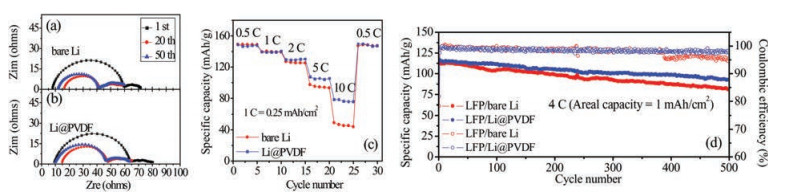
The interfacial stability of electrodes can be studied by electrochemical impedance spectroscopy (EIS) on symmetric cells after the specific cycles at 0.5 mA/cm2 with a cycling capacity of 0.5 mAh/cm2. The semi-circle in high frequency region can be a good sign of the interfacial resistance between electrode/electrolyte and transfer resistance of anode surface [29]. The difference of interfacial resistance between the pristine bare and PVDF-coated Li metal electrodes is much obvious. However, this difference became indistinct on the 1-, 20- and 50-cycled electrodes, as demonstrated in Fig. S3 (Supporting information) and Fig. 3. The high frequency interception has a decrease during cycling which could be related to the larger surface area resulting from the Li dendrites during cycling. The larger surface area could reduce the current density and the charge transfer resistance [29, 30].

|
Download:
|
| Fig. 3. (a, b) Impedance spectroscopy. Nyquist plots of the symmetric cells of bare Li electrode and Li@PVDF electrode after 1 cycle, 20 cycles and 50 cycles cycling. (c) Rate performance of the LFP/Li cells with bare Li and Li@PVDF composite anode at different current rates. (d) Prolonged cycling performance of the LFP/Li cells with bare Li and Li@PVDF composite anode at 4 C. | |
Galvanostatic cycling of full cells with lithium iron phosphate (LiFePO4, LFP) are used to compare the rate capability, long-time cycling capacity and coulombic efficiency of bare Li electrode and Li@PVDF electrode. Rate performance shown in the Fig. 3c depicts that the Li@PVDF electrode has an outstanding rate performance than bare Li electrode. Detailedly, there are similar specific capacities of both bare Li electrode and Li@PVDF electrode at low rates from 0.5 C (1 C = 170 mAh/g or 0.25 mAh/cm2) to 2 C (the specific capacities of both electrodes are about 148.7 mAh/g, 139.4 mAh/g and 129.4 mAh/g at 0.5 C, 1 C and 2 C, respectively). However, the capacities of the two electrodes become different at higher rate. The electrode with the protection of PVDF layer owns larger discharge capacities which are 107.4 mAh/g at 5 C and 78.4 mAh/g at 10 C, while capacities of cells without modification are only 97.4 mAh/g and 49.1 mAh/g at 5 C and 10 C. Moreover, the reversible capacity of Li@PVDF electrode is 149.4 mAh/g when the cycling rate turns back to 0.5 C.
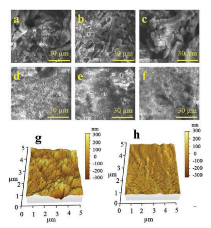
From Fig. 3d, the prolong-cycle performance and coulombic efficiency of Li@PVDF electrode is better than that of bare Li electrode. In initial cycle, the bare Li electrode presents a discharge capacity of 112 mAh/g. As a comparison, the Li@PVDF electrode has a higher capacity of 115 mAh/g in the first cycle, and it also has a higher discharge capacity of 92 mAh/g than that of bare Li electrode (81 mAh/g) after 500 cycles at 4 C. The capacity retention of Li@PVDF electrode is 80.0% at the end of 500 cycles which is also higher than that of bare Li electrode (72.3%). What is more, Li@PVDF electrode keeps a stable coulombic efficiency of ~98% at the whole cycling process, while the coulombic efficiency of bare Li electrode debase to ~95.5% at the 390th cycle. At a smaller current density of 2 C, the better prolonged cycling performance of LFP cells with the Li@PVDF electrode can also be detected in the Fig. S4. The Li@PVDF electrode delivers high capacity retention of 89.8% corresponding to an average capacity decay of 0.03% each cycle. For the bare Li electrode, however, the capacity retention is just 82.7% after 300 cycles. These enhanced performances of Li@PVDF electrode further testify that the thin PVDF layer is beneficial for enhancing the cycle stability of Li metal batteries. Fig. 4 displays the top face morphologies of the bare Li electrode and Li@PVDF electrode with different cycles at a fixed current density of 0.5 mA/cm2 using symmetric cells. As shown in Fig. 4a, only after 10 cycles, some tiny dendrites appear on the surface of the bare Li electrode, which makes the surface of Li electrode rugged. Moreover, larger strip-like dendrites and more rough morphology on the outside of the bare Li electrode are discovered after 20 cycles (Fig. 4b). After 50 cycles in Fig. 4c, one can see that a large number of Li metals particles have serious aggregation, and the block-like Li metals separate from each other leading to many fissures and ridges, indicating that the structure of the bare Li electrode has been damaged seriously. On the contrary, no obvious formation of dendrites can be found on the surface of the Li@PVDF electrode after 10 cycles (Fig. 4d), 20 cycles (Fig. 4e) and 50 cycles (Fig. 4f). Besides, the cross-section SEM images of Li@PVDF electrode cycled at 0.5 mA/cm2 with a capacity of 0.5 mAh/cm2 after 20 cycles in Fig. S5 (Supporting information) could prove that the deposited Li is between the PVDF film and the Li substrate. The porous insulative PVDF film could prevent reduction of Li ions on the surface. And the potential gradient between this film and Li substrate help to plate metallic Li underneath this film [31]. Thus, PVDF layer can validly guide the nucleation process of Li-metal and relieve local overgrowth of Li dendrites to obtain a perfect surface topography.

|
Download:
|
| Fig. 4. Top-view SEM images of bare Li electrode after (a) 10 cycle, (b) 20 cycles, (c) 50 cycles and Li@PVDF electrode after (d) 10 cycle, (e) 20 cycles and (f) 50 cycles at 0.5 mA/cm2 with a capacity of 0.5 mAh/cm2 in per cycle. AFM images of (g) bare Li electrode and (h) Li@PVDF electrode cycled at 0.5 mA/cm2 with a capacity of 0.5 mAh/cm2 after 50 cycles. | |
Atomic force microscopy (AFM) is used to clearly show the 3D morphology of two different electrodes under the same testing. After 50 cycles at 0.5 mA/cm2 with a stripping/plating capacity of 0.5 mAh/cm2, the bare Li electrode presents an abundant mountain-like rough surface, which indicates the serious damage of the electrode (Fig. 4g). However, only a slight surface ups and downs without crack can be observed on the Li@PVDF electrode (Fig. 4h), which further proves that the better electrochemical deposition of Li under the protection of PVDF film can easily be realized. Relative height profiles in Fig. S6c (Supporting information) accurately represent the relative height of two electrodes corresponding to the black dotted line areas in Figs. S6a and S6b (Supporting information), respectively. For bare Li electrode, the relative height is much larger (the biggest relative height is nearly 388.3 nm) and the peaks of the curve are sharper. However, for Li@PVDF electrode, the relative height is less than 117.8 nm and the relative height curve is gentler. These significant differences between the two electrodes indicate that the PVDF film contributes to uniform distribution of Li and effectively restrains the growth of Li dendrites.
In summary, we have certified that the Li@PVDF electrode prepared by a simple method could effectively prevent the growth of Li dendrites and realize a stable long-time cycling performance. Above all, the porous structure of PVDF layer provides transmission channel for Li ions to overcome the poor ionic conductivity of PVDF, realize the uniform electrodeposition of Li under this layer. Secondly, the favourable mechanical stability of PVDF film could protect Li metal electrode from the problem of structure damage and augment the long cycling performance. More importantly, the simple method as well as low cost of PVDF material would promote its practical application.
AcknowledgmentsThis work is supported by the National Natural Science Foundation of China (Nos. 21621091, 21273184), and the National Key Research and Development Program of China (No. 2016YFB0100202).
Appendix A. Supplementary dataSupplementary material related to this article can be found, in the online version, at doi:https://doi.org/10.1016/j.cclet.2018.05.016.
| [1] |
C.F. Zhang, S.J. Kim, M. Ghidiu, et al., Adv. Funct. Mater. 26 (2016) 4143-4151. DOI:10.1002/adfm.v26.23 |
| [2] |
C.F. Zhang, S.H. Park, S.E. O'Brien, et al., Nano Energy 39 (2017) 151-161. DOI:10.1016/j.nanoen.2017.06.044 |
| [3] |
C.F. Zhang, S.H. Park, O. Ronan, et al., Small 13 (2017) 1701677. DOI:10.1002/smll.v13.34 |
| [4] |
Y.J. Weia, Y.Q. Tao, C.F. Zhang, et al., Electrochim. Acta 188 (2016) 385-392. DOI:10.1016/j.electacta.2015.12.012 |
| [5] |
J.M. Tarascon, M. Armand, Nature 414 (2001) 359-367. DOI:10.1038/35104644 |
| [6] |
W. Xu, J.L. Wang, F. Ding, et al., Energy Environ. Sci. 7 (2014) 513-537. DOI:10.1039/C3EE40795K |
| [7] |
L. Suo, Y.S. Hu, H. Li, et al., Nat. Commun. 4 (2013) 1481. DOI:10.1038/ncomms2513 |
| [8] |
W. Li, H. Yao, K. Yan, et al., Nat. Commun. 6 (2015) 7436. DOI:10.1038/ncomms8436 |
| [9] |
X.Q. Zhang, X.B. Cheng, X. Chen, C. Yan, Q. Zhang, Adv. Funct. Mater. 27 (2017) 1605989. DOI:10.1002/adfm.v27.10 |
| [10] |
Y. Liu, D.C. Lin, P.Y. Yuen, et al., Adv. Mater. 29 (2017) 1605531. DOI:10.1002/adma.201605531 |
| [11] |
G.Y. Zheng, S.W. Lee, Z. Liang, et al., Nat. Nanotechnol. 9 (2014) 618-623. DOI:10.1038/nnano.2014.152 |
| [12] |
N.W. Li, Y.X. Yin, C.P. Yang, Y.G. Guo, Adv. Mater. 28 (2016) 1853-1858. DOI:10.1002/adma.201504526 |
| [13] |
X.B. Cheng, H.J. Peng, J.Q. Huang, et al., ACS Nano 9 (2015) 6373-6382. DOI:10.1021/acsnano.5b01990 |
| [14] |
H.K. Kang, S.G. Woo, J.H. Kim, et al., ACS Appl. Mater. Interfaces 8 (2016) 26895-26901. DOI:10.1021/acsami.6b09757 |
| [15] |
C.P. Yang, Y.X. Yin, S.F. Zhang, N.W. Li, Y.G. Guo, Nat. Commun. 6 (2015) 8058. DOI:10.1038/ncomms9058 |
| [16] |
Q. Yun, Y.B. He, W. Lv, et al., Adv. Mater. 28 (2016) 6932-6939. DOI:10.1002/adma.201601409 |
| [17] |
Y.M. Sun, G.Y. Zheng, Z.W. Seh, et al., Chemistry 1 (2016) 287-297. DOI:10.1016/j.chempr.2016.07.009 |
| [18] |
R. Zhang, N.W. Li, X.B. Cheng, et al., Adv. Sci. 4 (2017) 1600445. DOI:10.1002/advs.201600445 |
| [19] |
Z.Y. Tu, Y.Y. Lu, L. Archer, Small 11 (2015) 2631-2635. DOI:10.1002/smll.v11.22 |
| [20] |
Y.Y. Lu, M. Tikekar, R. Mohanty, et al., Adv. Energy Mater. 5 (2015) 1402073. DOI:10.1002/aenm.201402073 |
| [21] |
Q.W. Pan, D.M. Smith, H. Qi, S.J. Wang, C.Y. Li, Adv. Mater. 27 (2015) 5995-6001. DOI:10.1002/adma.201502059 |
| [22] |
D. Zhou, R.L. Liu, Y.B. He, et al., Adv. Energy Mater. 6 (2016) 1502214. DOI:10.1002/aenm.201502214 |
| [23] |
X.Y. Yao, D. Liu, C.S. Wang, et al., Nano Lett. 16 (2016) 7148-7154. DOI:10.1021/acs.nanolett.6b03448 |
| [24] |
X.G. Han, Y.H. Gong, K. Fu, et al., Nat. Mater. 16 (2017) 572-579. |
| [25] |
Liu Fu, N.A. Hashim, Y.T. Liu, M.R.M. Abed, K. Li, J. Membr. Sci. 375 (2011) 1-27. DOI:10.1016/j.memsci.2011.03.014 |
| [26] |
R. Xu, X.Q. Zhang, X.B. Cheng, et al., Adv. Funct. Mater. (2018) 1705838. |
| [27] |
J.E. Dohany, K. Othmer, Encycl. Chem. Technol. 1 (2000) 34-45. |
| [28] |
K. Yan, H.W. Lee, T. Gao, et al., Nano Lett. 14 (2014) 6016-6022. DOI:10.1021/nl503125u |
| [29] |
Q. Li, S. Zhu, Y.Y. Lu, Adv. Funct. Mater. 27 (2017) 1606422. DOI:10.1002/adfm.201606422 |
| [30] |
D. Lin, Y. Liu, Z. Liang, H.W. Lee, Nat. Nanotechnol. 11 (2016) 626-632. DOI:10.1038/nnano.2016.32 |
| [31] |
X. Liang, Q. Pang, I.R. Kochetkov, et al., Nat. Energy 2 (2017) 17119-17126. DOI:10.1038/nenergy.2017.119 |