 2019, Vol. 30


b Tsinghua-Berkeley Shenzhen Institute, Tsinghua University, Shenzhen 518055, China;
c School of Marine Science and Technology, Tianjin University, Tianjin 300072, China;
d School of Chemical Engineering and Technology, Tianjin University, Tianjin 300072, China
Lithium-sulfur (Li-S) battery is a promising candidate to replace the conventional lithium-ion batteries due to the earth abundance and low cost of sulfur, and the highly theoretical specific capacity (1672 mAh/g). However, there are still some obstacles hindering the practical application of Li-S batteries. First, sulfur and the discharge products of lithium sulfide have poor conductivity, resultinginthelow utilization ofactive materials. Second, the lithium polysulfides (LiPSs) formed during the charge and discharge process tend to dissolve into the electrolyte, which lowers the availability of sulfur [1, 2].
Carbon materials with high specific surface area and good conductivity have been used as sulfur hosts to solve the above problems [3-13]. Especially, the mesoporous carbon materials (MCMs) with relatively large pore volume can load more sulfur than the microporous carbon and provide enough space for the sulfur volume expansion. However, the MCMs cannot effectively restrain the polysulfide shuttling because of their large pore size and nonpolar surface inducing the poor affinity towards the polar LiPSs. Inaddition, their complicated pore structure usually increases the Li+ diffusion resistance, thus reducing the reaction kinetics. Transition metal oxides (TMO) have much stronger binding energy with LiPSs than carbon materials [14-22], but their poor electrical conductivity usually suppresses the reaction of LiPSs on their surface. Thus, the integration of MCMs and TMO is appealing to serve as an advanced multifunctional sulfur host for Li-S battery to effectively restrain the polysulfide shuttling and improve the utilization of active materials.
Herein, a MoO2-ordered mesoporous carbon CMK-3 (M-OMC) hybrid was prepared by an in-situ thermal reduction method, in which the OMC can act as the nanoreactor, and its ordered mesoporous pores can load more sulfur and provide channels for fast ion transport. The conductive mesoporous carbon framework and the high conductivity of MoO2 (190 S/cm) [23, 24] guarantee the excellent conductivity of the cathode materials. Moreover, the chemical interaction between MoO2 and polysulfides not only inhibits the shuttling of polysulfides [16], but also confines the active materials in the OMC matrix. The high conductivity and the interaction synergistically contribute to the high utilization of sulfur. In addition, the MoO2 can catalyze the conversion between sulfur and polysulfides. Furthermore, MoO2, as a stable secondary active material, provides additional capacity (71 mAh/g) for Li-S batteries. As a result, the MoO2-CMK-3-S (M-OMC-S) cathode delivers a stable discharge capacity of 800 mA h/g at 0.5C after 300 cycles, much higher than that of the CMK-3 (ordered mesoporous carbon, denoted as OMC) cathode. As a result, this work presents an attractive design method for TMO/carbon hybrids used in lithium-sulfur batteries.
The preparation process of the M-OMC and M-OMC-S hybrid is illustrated in Fig. 1a. Firstly, the OMC as a carbon source was soaked in the ammonium molybdate solution, then after vacuum filtration and drying, the mixture was calcined in the furnace under Ar/H2 protection at 650 ℃ to form the M-OMC hybrid. The as-prepared M-OMC hybrid and sulfur powder with a mass ration of 3:7 were ground together for 15 min, following by a heat-treatment at 155 ℃ for 10 h in a sealed vessel filled with argon gas protection to ensure a complete infiltration of sulfur into the mesopores of OMC. After the cooling process, the M-OMC-S hybrids were obtained.

|
Download:
|
| Fig. 1. a) Schematic illustration of the preparation process of the M-OMC and M-OMC-S hybrid. The octahedrons represent MoO2 nanoparticles. SEM images of b) the OMC and c) the M-OMC hybrid. d) SEM images and the corresponding e) C, f) Mo, and g) S elemental mapping of the M-OMC-S hybrid. TEM images of h) the OMC, i) M-OMC, and j) M-OMC-S hybrid. | |
As shown in Fig. 1b, the OMC consists of micrometer-sized rodlike particles. While for the M-OMC hybrid, as shown in Fig. 1c, it still keeps the morphology and the interconnected pore structure, similar to the OMC, and no bulk MoO2 was observed, which should be attributed to its small particle size. When sulfur was infiltrated into the OMC framework through heat melt-diffusion method, the carbon strips of the OMC became cohesive (Fig. 1d). Elemental mapping (Figs. 1e-g) of the M-OMC-S hybrid further verifies that the sulfur had uniformly impregnated into the pores of OMC. In addition, the distribution of sulfur well matches that of Mo, indicating that MoO2 has a strong interaction with sulfur. The transmission electron microscopy (TEM) image (Fig. 1h) demonstrates that the OMC is composed of highly ordered pore channels, which provide fast Li+ transport channel. The high-resolution TEM (HRTEM) image of M-OMC (Fig. 1i) shows that the distance between two adjacent lattice fringes is 0.028 and 0.049 nm, corresponding to the (102) and (010) crystalline plane of monoclinic MoO2 (JCPDS No. 65-5787), respectively [25]. The MoO2 particles, with an average size about 15 nm (Fig. S1 in Supporting information), disperse quite evenly on the outer surface of the OMC due to the larger size than the channel of CMK-3. The MoO2 'guardian' cannot only prevent polysulfide migrating out of the pores of OMC, but also have no effect on the long and complete ion transport channel of OMC. The TEM image of M-OMC-S (Fig. 1j) shows that the hybrid keeps the original morphology of OMC, which implies that the structural integrity of electronic transportation channel is not violated.
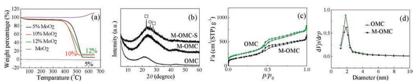
Thermogravimetric (TG) analysis was carried out in air atmosphere to determine the content of MoO2 in the M-OMC hybrid. As shown in Fig. 2a, the M-OMC undergoes obvious weight loss when the temperature increases up to 350 ℃ due to the oxidation of OMC. The thermogravimetric (TG) analysis of sulfur (Fig. S2b in Supporting information) displays that the content of S is 67 wt%, corresponding to the areal sulfur mass loading about 1.0 mg/cm2. The M-OMC hybrids with different contents of MoO2 are prepared, and the hybrid with 10 wt% MoO2 is found to have the best electrochemical performance (Fig. S3a in Supporting information) since extra MoO2 decreases the conductivity of the cathode (Fig. S3b in Supporting information) and the low MoO2 content cannot well restrain the LiPS shuttling. For the hybrid with 10 wt% MoO2, the areal mass loading of OMC and MoO2 was about 0.5 mg/cm2 and 0.05 mg/cm2, respectively. Fig. 2b shows the XRD patterns of the OMC, M-OMC and M-OMC-S hybrids. The broad peaks of OMC at around 21° and 43° are attributed to the (002) and (101) diffractions of graphitic structure. The shift of the (002) peak is probably due to the interaction force between MoO2 and graphitic carbons. It is important to note that the M-OMC hybrid does not reveal the typical diffraction peaks of MoO2, which should be attributed to the small particle size of MoO2.

|
Download:
|
| Fig. 2. a) TG curves of the M-OMC hybrid with different content of MoO2. b) XRD patterns of the OMC, M-OMC, and M-OMC-S hybrid. c) N2 adsorption/desorption isotherms of the OMC and M-OMC hybrid and d) the corresponding pore-size distribution. | |
To find out whether the formation of MoO2 influenced the pore structure of the OMC, nitrogen adsorption/desorption measurements are carried out. Figs. 2c and d show the N2 adsorption/ desorption isotherms and pore-size distribution of the OMC and M-OMC hybrid, respectively. After MoO2 formation, the pore-size distribution had very little changes compared with OMC, indicating the MoO2 does not occupy the pore channels of the OMC, which can make sure the OMC can supply enough space to load large amount of sulfur, accommodate the volume expansion during the charge and discharge process. From the TEM images (Fig. S1a) of the M-OMC-S hybrid, most MoO2 are formed outside the pores of OMC, which help confine the sulfur and polysulfides in the pore channels, preventing them migrating out of OMC.
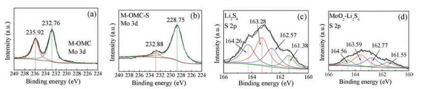
X-ray photoelectron spectroscopy (XPS) was used to investigate the chemical state of the M-OMC-S hybrid. As shown in Fig. 3a, the double peaks of M-OMC at 232.76 eV and 235.92 eV are attributed to Mo 3d5/2 and Mo 3d3/2 of Mo6+, respectively [24]. The presence of Mo6+ is generally observed in the Mo 3d XPS spectra of MoO2 reported in literatures [26], which can be ascribed to the slight oxidation of metastable MoO2 in the air. In the case of M-OMC-S (Fig. 3b), the doublets at 228.75 eV and 232.88 eV are characteristic of Mo 3d5/2 and Mo 3d3/2 of Mo4+. The transformation from Mo6+ to Mo4+ on the surface of MoO2 particles indicates that the infiltrated sulfur has interaction with Mo or O atom. Therefore, the XPS study of S spectra was also performed. The S 2p XPS spectra of S (Fig. S4a in Supporting information) can be deconvoluted into two peaks. The peaks at 163.73 and 165.11 eV are assigned to S 2p3/2 and S 2p1/2 of S, respectively, due to spin orbit coupling [27]. However, after S was infiltrated into the M-OMC hybrid, another peak at 165.63 eV appears (Fig. S4c in Supporting information), usually suggesting the presence of SO32-. We propose that the Mo6+ in the M-OMC hybrid can oxidize S via the reaction shown below (Eq. (1)):

|
(1) |

|
Download:
|
| Fig. 3. XPS spectra of the interaction between sulfur and MoO2. a) high-resolution Mo 3d spectra of the M-OMC hybrid; b) high-resolution Mo 3d spectra of the M-OMC-S hybrid; c) high-resolution S 2p spectra of Li2S6; d) high-resolution S 2p spectra of MoO2-Li2S6. | |
Fig. 3c shows the S 2p spectra of Li2S6. The spectrum of a dried Li2S6 solution features two doublet components centered at 161.38/162.57 eV and 163.28/164.26 eV, corresponding to the terminal S atoms (ST) directly bonded with Li and the bridging S atoms (SB) directly bonded with S [28]. The areal ratio of SB to ST is roughly consistent with the nominal formula Li2S6. Li2S6 adsorbed on MoO2 (Fig. 3d) manifests a more decreased SB/ST ratio (~1:1) than Li2S6, showing the transformation of longer-chain LiPSs to shorter-chain LiPSs on MoO2 surface, which further testified that the MoO2 inlaid OMC can catalyze the polysulfide reactions to further effectively improve the utilization of active materials [16].
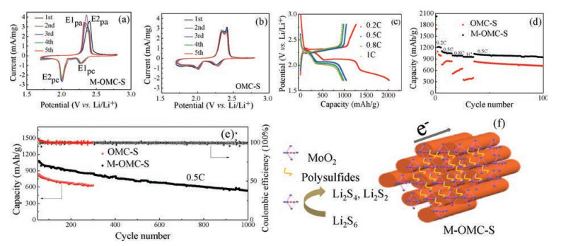
The electrochemical properties of the M-OMC-S and OMC-S cathodes are evaluated by assembling them into Li-S batteries with Li-foil as the anode. Fig. 4a shows the cyclic voltammetry (CV) curves of the M-OMC-S cathode recorded at 0.1 mV/s. Two cathodic peaks at about 2.29 eV and 2.01 eV are observed, which corresponds to sulfur (S8) converting to soluble long chain polysulfides (Li2Sn, 4 ≤ n ≤ 8) and long-chain LiPSs form insoluble Li2S2/Li2S, respectively [29]. When scanning back to 2.8 V, the overlapping anodic peak centered at about 2.35 V corresponds to the delithiation of Li2S to Li2Sn and eventually to elemental sulfur. From the 1st cycle to 5th cycle of CV profiles, potential differences between the anodic peak and cathodic peak decrease, suggesting faster electrochemical kinetics. Compared with the CV profiles of the OMC-S cathode (Fig. 4b), the E2pc of the M-OMC-S cathode shows higher intensity and narrower peak, suggesting the reaction occurred at this potential is greatly enhanced, which means the transformation of soluble LiPSs to final insoluble products is promoted, indicating the decreasing possibilities for the LiPSs shuttling into the electrolyte. Fig. 4c shows the galvanostatic discharge/charge voltage profiles of the M-OMC-S cathode at different current rates. The M-OMC-S cathode can deliver high discharge capacities of 1045, 983 and 951 mAh/g with the current densities of 0.5C, 0.8C and 1C, respectively. With the increase of the current density and prolonged cycles (Fig. S5a in Supporting information), the potential hysteresis between discharge and charge profiles in the M-OMC-S cathode is not obvious, indicating the fast electrochemical kinetics of sulfur hosted in the M-OMC hybrid. It is possibly because of the high conductivity, the ordered electronand electrolyte transportationof the M-OMC, and the high utilization of sulfur as a result of the binding energy and catalysis between MoO2 and LiPSs. But for OMC-S cathode, the specific capacity fades quickly (Fig. 4d, from 1017 mAh/g to 399 mAh/g) as the rate increases from 0.2C to 1C. It is worth noting that for the MOMC-S cathode, the specific capacity of the first cycle has gone beyond the theoretical capacity of sulfur. It is because when the potential window is between 1.7 and 2.8 V, MoO2 nanoparticles can store Li+ (Fig. S5b in Supporting information) with the following conversion reaction mechanism [30]:

|
(2) |

|
Download:
|
| Fig. 4. a) Cyclic voltammograms (CV) of the M-OMC-S and b) OMC-S cathode at a scanning rate of 0.1 mV/s; c) Galvanostatic discharge/charge voltage profiles of the M-OMC-S cathode at different rates (0.2C, 0.5C, 0.8C, 1C); d) Rate capability of the M-OMC-S and OMC-S cathode at different current densities. (The test potential window is between 1.7 V and 2.8 V vs. Li+/Li); e) Cycling performance of the M-OMC-S and OMC-S cathodes at 0.5C; f) Schematic illustration of polysulfide transformation on the M-OMC. | |
Thus, MoO2 nanoparticles have a theoretical specific capacity of 838 mAh/g [31]. From Fig. 4d, it can be assumed the initial specific capacity of only sulfur in M-OMC-S is to be 1690 mAh/g, indicating a high accessibility of sulfur. We also prepared MoO2 particles as the cathode of lithium-ion batteries. As shown in Fig. S6a (Supporting information), at the first cycle, MoO2 cathode shows a specific capacity of about 600 mAh/g. However, its capacity keeps at about 70 mAh/g since the second cycle (Fig. S6b in Supporting information). The long-term cycling stability of the integrated electrode was further evaluated at 0.5C for up to 1000 cycles, as shown in Fig. 4e. The cell remains a reversible discharge capacityof 533 mAh/g after 1000 cycles with a capacity fade of only 0.04% per cycle since the second cycle, and the average Coulombic efficiency was calculated to be above 98.5%, demonstrating excellnet cycling stability and high reversibility. This excellent electrochemical performance demonstrates the advantages of this rational design for advanced Li-S batteries. As shown in Fig. 4f, the OMC with high specificsurface areaand largeporevolumecan accommodatelarge amounts of sulfur and confine the polysulfide within the pores. And its ordered mesopore channel can effectively promote Li ion transport, while the MoO2 nanoparticles inlaid on the surface of the OMC can ensure the polysulfides confined in the frame of OMC, which can not only reduce the shuttle of polysulfides, but also make electrons react with sulfur easier.
In summary, we have designed a M-OMC hybrid for Li-S batteries, in which MoO2 nanoparticles are inlaid on the surface of the OMC. For the M-OMC-S cathode material, OMC can store active materials and provide fast electron transportation channel while the peripheric MoO2 can effectively prevent the migration of polysulfides through the chemical interaction. With a sulfur content of about 67%, the M-OMC-S cathode exhibits a superior high-rate capability and stable long-term cycle life within 1000 cycles. The excellent electrochemical performance of M-OMC-S cathode can be attributed to the fast electron transportation channel of OMC and the chemical interaction between the MoO2 nanoparticles and polysulfides that can significantly promote the conversion of polysulfides to hinder their shuttling. This rational structural configuration can also be extended to other metal oxides applied in Li-S batteries.
AcknowledgmentThis work was supported by the National Natural Science Foundation of China (Nos. U1710109 and 51702182) and Shenzhen Basic Research Project (No. JCYJ20150529164918734).
Appendix A. Supplementary dataSupplementary data associatedwith this article can be found, in the online version, at https://doi.org/10.1016/j.cclet.2018.04.019.
| [1] |
F. Liu, Q. Xiao, H.B. Wu, et al., ACS Nano 11 (2017) 2697-2705. DOI:10.1021/acsnano.6b07603 |
| [2] |
B. Yan, X. Li, Z. Bai, et al., J. Power Sources 338 (2017) 34-48. DOI:10.1016/j.jpowsour.2016.10.097 |
| [3] |
Z. Zhang, Z. Li, F. Hao, et al., Adv. Funct. Mater. 24 (2014) 2500-2509. DOI:10.1002/adfm.201303080 |
| [4] |
C. Nan, Z. Lin, H. Liao, et al., J. Am. Chem. Soc. 136 (2014) 4659-4663. DOI:10.1021/ja412943h |
| [5] |
Q. Sun, B. He, X.Q. Zhang, A.H. Lu, ACS Nano 9 (2015) 8504-8513. DOI:10.1021/acsnano.5b03488 |
| [6] |
Z. Li, L. Yuan, Z. Yi, et al., Adv. Energy Mater. 7 (2014) 1301473. |
| [7] |
X. Ji, S. Evers, R. Black, L.F. Nazar, Nat. Commun. 2 (2011) 325. DOI:10.1038/ncomms1293 |
| [8] |
H. Wang, Y. Yang, Y. Liang, et al., Nano Lett. 11 (2011) 2644-2647. DOI:10.1021/nl200658a |
| [9] |
S. Niu, W. Lv, G. Zhou, et al., Chem. Commun. 51 (2015) 17720-17723. DOI:10.1039/C5CC07226C |
| [10] |
J. Song, T. Xu, M.L. Gordin, et al., Adv. Funct. Mater. 24 (2014) 1243-1250. DOI:10.1002/adfm.v24.9 |
| [11] |
C. Zhang, Q.H. Yang, Sci. China Mater. 58 (2015) 349-354. DOI:10.1007/s40843-015-0051-4 |
| [12] |
Y. Xie, H. Cheng, W. Chai, et al., Chin. Chem. Lett. 28 (2017) 738-742. DOI:10.1016/j.cclet.2016.07.030 |
| [13] |
H. Zhang, Z. Zhao, Y. Liu, et al., J. Energy Chem. 26 (2017) 1282-1290. DOI:10.1016/j.jechem.2017.08.016 |
| [14] |
D. Xiao, C. Lu, C. Chen, et al., Energy Storage Mater. 10 (2018) 216-222. DOI:10.1016/j.ensm.2017.05.015 |
| [15] |
H. Yuan, W. Zhang, J. Wang, et al., Energy Storage Mater. 10 (2018) 1-9. DOI:10.1016/j.ensm.2017.07.015 |
| [16] |
R. Fang, S. Zhao, Z. Sun, et al., Energy Storage Mater. 10 (2018) 56-61. DOI:10.1016/j.ensm.2017.08.005 |
| [17] |
Q. Zhang, Y. Wang, Z.W. Seh, et al., Nano Lett. 15 (2015) 3780-3786. DOI:10.1021/acs.nanolett.5b00367 |
| [18] |
X. Liang, C. Hart, Q. Pang, et al., Nat. Commun. 6 (2015) 5682. DOI:10.1038/ncomms6682 |
| [19] |
T. Zhou, W. Lv, J. Li, et al., Energy Environ. Sci. 10 (2017) 1694-1703. DOI:10.1039/C7EE01430A |
| [20] |
D. Liu, C. Zhang, G. Zhou, et al., Adv. Sci. 5 (2018) 1700270. DOI:10.1002/advs.201700270 |
| [21] |
T. Zhou, Y. Zhao, G. Zhou, et al., Nano Energy 39 (2017) 291-296. DOI:10.1016/j.nanoen.2017.07.012 |
| [22] |
X. Liu, J. Huang, Q. Zhang, L. Mai, Adv. Mater. 29 (2017) 1601759. DOI:10.1002/adma.v29.20 |
| [23] |
Q. Qu, T. Gao, H. Zheng, et al., Adv. Mater. Interfaces 2 (2015) 1500048. DOI:10.1002/admi.201500048 |
| [24] |
B. Hu, L. Mai, W. Chen, F. Yang, ACS Nano 3 (2009) 478-482. DOI:10.1021/nn800844h |
| [25] |
V. Eyert, R. Horny, K. Höck, S. Horn, J. Phys. Condens. Matter 12 (2000) 4923. DOI:10.1088/0953-8984/12/23/303 |
| [26] |
Y. Sun, X. Hu, W. Luo, Y. Huang, J. Mater. Chem. 22 (2012) 425-431. DOI:10.1039/C1JM14701C |
| [27] |
C. Zhang, W. Lv, W. Zhang, et al., Adv. Energy Mater. 4 (2014) 1301565. DOI:10.1002/aenm.201301565 |
| [28] |
Y. Zhong, K.R. Yang, W. Liu, et al., J. Phys. Chem. C 121 (2017) 14222-14227. DOI:10.1021/acs.jpcc.7b04170 |
| [29] |
C. Zheng, S. Niu, W. Lv, et al., Nano Energy 33 (2017) 306-312. DOI:10.1016/j.nanoen.2017.01.040 |
| [30] |
J. Auborn, Y. Barberio, J. Electrochem. Soc. 134 (1987) 638-641. DOI:10.1149/1.2100521 |
| [31] |
M. Liu, Q. Li, X. Qin, et al., Small 13 (2017) 1602539. DOI:10.1002/smll.v13.12 |