 2019, Vol. 30


b State Key Laboratory of Quality Research in Chinese Medicine, Macau Institute for Applied Research in Medicine and Health, Macau University of Science and Technology, Macau, China
Microdroplets are of significant interest in biochemical and biomedical fields, including single cell analysis [1-4], drug delivery [5] and tissue engineering [6, 7]. Water is essential to all life, and the formation of aqueous microdroplets is the basis for biological applications. However, the formation of discrete droplets by microfluidics relies on the use of immiscible phase [8, 9] in which the aqueous droplets would be surrounded by continuous oil phase or an oil intermediate layer, and the long-time exposure to oil phase and blocked mass transfer of encapsulated cells might bring about the problem of biocompatibility. Alternatively, some approaches such as liposome vesicles [10-12] and aqueous two phase system (ATPS) droplets [13-17] have been developed to overcome these drawbacks. Nevertheless, the microdroplets would freely flow in the continuous phase when collected after generation. Extra devices for spatial restriction and manipulation of microdroplets are required to further make use of these microdroplets. Though various techniques, such as magnetic [18, 19], electric [20] and acoustic control [21] of microdroplets have been developed, the widespread use of these methods may be limited its scale of manipulation, and these methods can only be manipulated on chip.
Microfibers, useful materials in tissue engineering and regenerative medicine [22-25], are recently combined with microfluidic emulsion technology, for generating emulsion droplets in hydrogel microfiber [26-29]. Hydrogel microfiber can act as a shell matrix to restrict the droplets inside, which may facilitate good manipulation and potentiality of various applications. However, generating and encapsulating w/w droplets in microfiber has not been reported yet, since the hydrophilicity of hydrogel microfibers is in favor of encapsulating oil droplets, which naturally leads to difficulty in encapsulation of w/w droplets in fiber.
Herein, we describe a rapid and simple microfluidic approach to produce w/w droplets encapsulated in microfiber. PEG/dextran is utilized to form w/w droplets, and sodium alginate is added in the continuous phase to cross-link with calcium ions, forming hydrogel microfiber. Microdroplets were embedded in a hydrophilic environment, and further manipulation were enabled by the fixed position in fiber. The size and pattern of the droplets can be adjusted by changing the flow rates, sizes and patterns of glass capillaries. Diffusion assay and cell culture in the w/w droplets showed high biocompatibility and loading capability of this system. Bacillus subtilis loaded in droplets in fiber shows NO2- removal ability and could be easily separated, revealing great potential in constructing bioreactors in droplet fibers. The method of easy generation of biocompatible w/w droplets in microfibers may have promising applications in biological, environmental science and engineering.
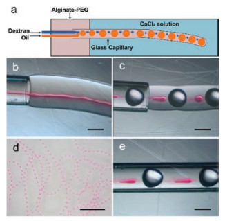
The fabrication of microfibers was illustrated in Fig. 1a. Aqueous two-phase system (ATPS) is formed when two incompatible aqueous solutions are mixed together and phase-separated above a critical concentration [30]. Because of the ultra-low interfacial tension of ATPS, the laminar flow is less perturbed for the slow growth of Rayleigh-Plateau instability [31], and it is quite challenging to form w/w emulsion droplets in ATPS spontaneously. As shown in Fig. 1b, a laminar flow of dextran formed in the microfiber without perturbation. Thus the oil droplets with a comparable size of the microchannel were introduced to this system: Oil droplet blocked the dextran flow, forming discrete dextran droplets in the microchannel (Fig. 1c). The fiber was generated at the outlet of glass capillary, embedded with oil droplets and aqueous dextran droplets (red color). Thus microdroplets encapsulated and immobilized in fibers can be generated in a short time (Fig. 1d).

|
Download:
|
| Fig. 1. (a) Schematic diagram of the generating process. Alginate-PEG, dextran and oil phase were introduced into the capillary, and the dextran flow was blocked by oil droplets. (b) The microfiber containing an ATPS flow jet without oil perturbation. (c) Formation of the w/w droplets in microfiber with perturbation of oil droplets. (d) Image of microfibers under a stereoscope. The dextran aqueous droplets were dyed with tsutsuji red. Transparent oil droplets and red aqueous droplets were placed in order. (e) The elliptical shaped droplets inside the capillary. Scale bars are 10 mm in (d) and 500 μm in (b), (c) and (e). | |
A shape change of w/w droplets from elongated ellipsoids to spheroids was observed at the outlet of capillary. We adopted the capillary number Ca to explain the shape change of microdroplets. Capillary number of dispersed phase Ca = μwvw/γATPS, in which the viscosity of the two aqueous phases were tested to be μw = 43.6 mPa s and μa = 55.6 mPa s, respectively, and the interfacial tension of two aqueous phases γATPS = 0.091 mN/m. vw was estimated by the difference of flow velocity, which can be calculated by flow rates and diameter of capillaries. Inside the glass capillary, calculated Ca ≈ 2.85 > 1, indicating the shape of dispersed phase was dominated by viscous force, and the droplets were impeded by high viscosity of two aqueous phases to become slender (Fig. 1e). When the dispersed phase flow out of the capillary, the continuous phase crosslinked to be hydrogel and therefore vw and Ca would decrease rapidly; therefore the dispersed phase would form a spherical shape by interfacial tension. The crosslink of hydrogel may also obstruct the movement of w/w droplets inside, which might explain the formation of satellite droplets. When the Qw is less than 1.0 μL/min, the formed hydrogel obstructs the droplets, as a result, the dispersed phase aggregated to more than one center instead of forming a single droplet.
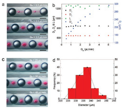
The flow rate of alginate (Qa), water droplet (Qw) and oil droplet (Qo) are investigated to manipulate the generation and size of ATPS droplets. As shown in Figs. 2a and b, when Qa and Qo were fixed at 105 μL/min and 30 μL/min respectively, the w/w droplets were generated smoothly and the diameter of w/w droplets (Dw) varies from 140 μm to 300 μm and increases with the increase of Qw. A larger cylindrical glass capillary (i.d. = 1.10 mm) and a smaller capillary (i.d. = 0.58 mm) with matched stainless tubes were employed, and the size range of water droplets and fibers was expanded (Fig. S3 in Supporting information). Different Qo values under fixed Qa are set to investigate oil phase's influence on Dw, and we observed that in a proper range of Qo/Qa, the generation of w/w droplets would not be affected (Fig. 2c). As shown in Fig. 2d, microfluidics offered good uniformity of diameter distribution of aqueous droplets, and aqueous droplets with a stable diameter could be generated with the fixed flow rate (Qw = 2 μL/min, Dw = 235.3 ± 6.2 μm). The diameter of alginate-PEG fiber (Da) is larger than the inner diameter (0.75 mm) of the cylindrical glass capillary. This phenomenon could be ascribed to the die swell effect [32]: The cross-link of alginate requires a short time, during which the extruded continuous phase swelled in absence of the capillary's constraint, causing a slight expansion in fiber's diameter.

|
Download:
|
| Fig. 2. (a) Microscopy images of the microfibers with varied Qw; Qa = 105 μL/min and Qo = 30 μL/min; The aqueous droplets were dyed with tsutsuji red. (b) Parameters of microfibers when Qa = 105 μL/min, Qo = 30 μL/min. L refers to the distance between two continuous oil droplets. (c) Microscopy images of the microfibers with varied Qo; Qa = 105 μL/min and Qw = 2 μL/min. (d) diameter distribution of aqueous droplets when the flow rates were fixed at Qa = 105 μL/min, Qo = 30 μL/min and Qw = 2 μL/min. Scale bars are 500 μm in (a) and (c). | |
The method described above provides a quite easy way to generate uniform aqueous droplets in fiber, and patterns of droplets could also be manipulated. Three identical stainless tubes were inserted in a glass capillary side by side, with the oil phase being introduced in the middle to block the two dispersed aqueous phase aside (Fig. 3a). As shown in Figs. 3b and c, the microfiber with two separated aqueous droplets was generated in fiber. The elliptical shape of the water droplets could be ascribed to the obstruction of capillary and fibers. With different pattern of droplets in fiber, the functional and loading diversity can be highly extended, and an asymmetric structure could also be realized if different flow rate or components were introduced.

|
Download:
|
| Fig. 3. (a) Schematic diagram of the generation process. (b) Image of microfibers with two aqueous droplets under a stereoscope, and the dextran aqueous droplets were dyed with tsutsuji red and brilliant blue. (c) Microscopy image of microfibers with two aqueous droplets. (d and e) Knotted droplet fiber under (d) stereoscope and (e)lightsheet microscopy. Scale bars are 5 mm in (b) and (d), 500 μm in (c) and (e). | |
Unlike other methods of w/w droplets generation, w/w droplets in fiber was fixed by surrounding hydrogel, enhancing easy manipulation of droplets by manipulating fibers [33]. With favorable mechanical strength, handling alginate fiber is quite convenient. Compared with manipulation of droplets in solution via external field, a large scale of droplets in fiber could be generated and manipulated off-chip more easily. Fibers could be transferred and knotted (Figs. 3d and e), therefore the microdroplets embedded in fibers can also be handled easily.
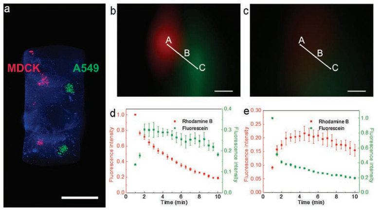
The w/w droplets encapsulated in hydrogel fiber would give rise to advantages in biological and environmental applications because of hydrogel surrounded environment and fiber format. Hydrogel could avoid the influence from surrounding oil phase in w/o emulsion, which should be favorable to cell culture. Herein the capability of cell loading and culture in microdroplets was investigated. A549 and MDCK cells were loaded in two separate microdroplets and labeled by CellTrackerTM fluorescent probes, showing cell co-loading abilities (Fig. 4a). The microdroplets owned high biocompatibility because of the hydrophilic environment, and A549 cells cultured inside maintained 85% viability after 7 days (Fig. S6 in Supporting information). Study of intercellular communications gives insight to the construction of microenivronment [34, 35], and microfibers encapsulating two aqueous droplets could be a candidate for construction of cell-cell interaction model, with different cells loaded and cultured in the controllable aqueous droplets with confined space. A diffusion assay was carried out to verify the interaction and mass transfer between neighboring w/w droplets. As shown in Figs. 4b and c, fluorescence intensity of the encapsulated aqueous droplets loading rhodamine B (50 μmol/L) and fluorescein (50 μmol/L) were observed over time. Mass transfer was not obstructed in the all-aqueous environment, so small molecules in two aqueous droplets diffused into each other, indicating capability of signal transmission and communication between the cells in two aqueous droplets (Figs. 4d and e).

|
Download:
|
| Fig. 4. (a) Microfibers (blue) encapsulating A549 cells (green) and MDCK cells (red) under lightsheet microscopy. (b and c) Diffusion assay of the microfiber. Fluorescence images were taken (b) 1 min and (c) 10 min after microfiber fabrication. Rhodamine B and fluorescein were encapsulated in two aqueous droplets separately. (d and e) Fluorescence intensity of rhodamine B and fluorescein at point A and C in Figs. 4b and c, respectively. Scale bars are 1 mm in (a) and 200 μm in (b) and (c). | |
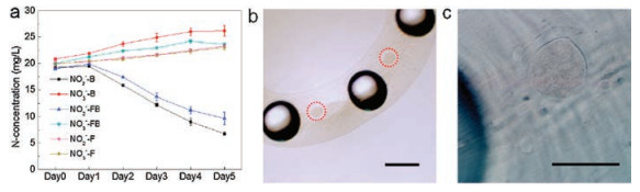
Compared with other w/w droplets, the fiber could act as a shell for encapsulated droplets, preventing cells from direct contact to external environment, which is beneficial to efficient separation and recycling. Bacillus subtilis could be loaded and cultured inside the aqueous droplets [36-38], and the w/w droplet fiber encapsulating Bacillus subtilis was applied to water remediation for its biologic nitrogen removal ability. The fibers were placed in water containing glucose (as carbon source), sodium nitrite and sodium nitrate as a polluted water sample. As shown in Fig. 5a, the decrease in concentration of NO2- was observed during 5 days' incubation. In oxygen-rich conditions, the denitrification procedure was inhibited [39], causing the slight increase of NO3- and thus NO2- was utilized and removed by Bacillus subtilis. Microbes encapsulated in droplet fiber exhibited similar water remediation ability to the non-encapsulated one. It should be pointed out in these experiments the water evaporation was not restricted and led to slightly increase of N-concentration after long-term incubation, which can be seen from the groups without Bacillus subtilis. But considering the water evaporation is comparable between all groups, it has little affect on the conclusion. Bioremediation of microbes is widely used in water purification process, while the microbe loss and contamination of microbes should be avoided [40]. Here the leakage was prevented by complete encapsulation of droplets inside alginate hydrogel. Moreover, after 5 days' incubation, no deformation of the fiber encapsulating Bacillus subtilis was observed (Fig. 5b), which suggested the manipulation and recycling capability of the fiber. As discussed above, more than one type of aqueous droplet could be introduced to the microfiber, and the loading diversity would facilitate various applications by loading different microbes in different microdroplets.

|
Download:
|
| Fig. 5. (a) Concentration of NO2--N and NO3--N in polluted water sample. FB: bacteria encapsulated in droplet fiber; B: non-encapsulated bacteria; F: droplet fiber without bacteria. (b) The hydrogel fiber encapsulating w/w droplets (marked in red circle) with Bacillus subtilis inside after 5 days' incubation. (c) w/w droplets encapsulated in fiber in Fig. 5b. Scale bars are 500 μm in (b) and 200 μm in (c). | |
In summary, we have reported a simple microfluidic approach to generate of w/w droplets encapsulated in hydrogel microfibers. Hydrogel provided a shell matrix for easy manipulation to embedded microdroplets, and the size and pattern of both microfibers and encapsulated droplets can be adjusted by changing the flow rates, sizes and patterns of glass capillary. Cells can be encapsulated in aqueous droplets in fiber for further manipulation, and permeability and biocompatibility are investigated by diffusion assay and long-term cell culture. Fiber format enhanced recycling capability, and nitrite-N removal from sewage was performed by encapsulated Bacillus subtilis in droplets, showing the great potential of fiber format containing aqueous microdroplets in bioreactor applications. This flexible and rapid fabrication method for w/w droplets encapsulated in microfiber would have promising development in biological and environmental fields.
AcknowledgmentsThis work was financially supported by the National Natural Science Foundation of China (Nos. 81872835, 21621003), Ministry of Science and Technology (Nos. 2017YFC0906902 and 2017ZX09301032), and Macau Science and Technology Development Fund (No. 129/2017/A3).
Appendix A. Supplementary dataSupplementary material related to this article canbefound, in the online version, at doi:https://doi.org/10.1016/j.cclet.2018.09.010.
| [1] |
A.B. Theberge, F. Courtois, Y. Schaerli, et al., Angew. Chem. Int. Ed. 49 (2010) 5846-5868. DOI:10.1002/anie.200906653 |
| [2] |
E.Z. Macosko, A. Basu, R. Satija, et al., Cell 161 (2015) 1202-1214. DOI:10.1016/j.cell.2015.05.002 |
| [3] |
C.G. Yang, R.Y. Pan, Z.R. Xu, Chin. Chem. Lett. 26 (2015) 1450-1454. DOI:10.1016/j.cclet.2015.10.016 |
| [4] |
L. Li, W. Wang, M. Ding, G. Luo, Q. Liang, Anal. Chem. 88 (2016) 6734-6742. DOI:10.1021/acs.analchem.6b01008 |
| [5] |
M. Windbergs, Y. Zhao, J. Heyman, D.A. Weitz, J. Am. Chem. Soc. 135 (2013) 7933-7937. DOI:10.1021/ja401422r |
| [6] |
R. Wieduwild, S. Krishnan, K. Chwalek, et al., Angew. Chem. Int. Ed. 54 (2015) 3962-3966. DOI:10.1002/anie.201411400 |
| [7] |
D.R. Griffin, W.M. Weaver, P.O. Scumpia, D.D. Carlo, T. Segura, Nat. Mater. 14 (2015) 737-744. DOI:10.1038/nmat4294 |
| [8] |
H. Lee, C.H. Choi, A. Abbaspourrad, et al., Adv. Mater. 28 (2016) 8425-8430. DOI:10.1002/adma.v28.38 |
| [9] |
L. Kong, E. Amstad, M. Kai, et al., Chin. Chem. Lett. 28 (2017) 1897-1900. DOI:10.1016/j.cclet.2017.07.017 |
| [10] |
D.L. Richmond, E.M. Schmid, S. Martens, et al., Proc. Natl. Acad. Sci. U. S. A. 108 (2011) 9431-9436. DOI:10.1073/pnas.1016410108 |
| [11] |
N.N. Deng, M. Yelleswarapu, W.T. Huck, J. Am. Chem. Soc. 138 (2016) 7584-7591. DOI:10.1021/jacs.6b02107 |
| [12] |
S. Deshpande, Y. Caspi, A.E. Meijering, C. Dekker, Nat. Commun. 7 (2016) 10447. DOI:10.1038/ncomms10447 |
| [13] |
Y.S. Song, Y.H. Choi, D.H. Kim, J. Chromatogr. A 2 (2007) 180-186. |
| [14] |
B.U. Moon, N. Abbasi, S.G. Jones, D.K. Hwang, S.S.H. Tsai, Anal. Chem. 88 (2016) 3982-3989. DOI:10.1021/acs.analchem.6b00225 |
| [15] |
I. Ziemecka, V. van Steijn, G.J.M. Koper, et al., Lab Chip 11 (2011) 620-624. DOI:10.1039/C0LC00375A |
| [16] |
H.C. Shum, J. Varnell, D.A. Weitz, Biomicrofluidics 6 (2012) 012808. DOI:10.1063/1.3670365 |
| [17] |
C. Zhou, P. Zhu, Y. Tian, et al., Lab Chip 17 (2017) 3310-3317. DOI:10.1039/C7LC00696A |
| [18] |
K. Zhang, Q. Liang, S. Ma, et al., Lab Chip 9 (2009) 2992-2999. DOI:10.1039/b906229g |
| [19] |
K. Zhang, Q. Liang, X. Ai, et al., Lab Chip 11 (2011) 1271-1275. DOI:10.1039/c0lc00484g |
| [20] |
D.R. Link, E. Grasland-Mongrain, A. Duri, et al., Angew. Chem. Int. Ed. 45 (2006) 2556-2560. |
| [21] |
D.J. Collins, T. Alan, K. Helmerson, A. Neild, Lab Chip 13 (2013) 3225-3231. DOI:10.1039/c3lc50372k |
| [22] |
Y. Jun, E. Kang, S. Chae, S.H. Lee, Lab Chip 14 (2014) 2145-2160. DOI:10.1039/C3LC51414E |
| [23] |
P. Xu, R. Xie, Y. Liu, et al., Adv. Mater. 29 (2017) 1701664. DOI:10.1002/adma.v29.34 |
| [24] |
J. Cheng, Y. Jun, J. Qin, S.H. Lee, Biomaterials 114 (2017) 121-143. DOI:10.1016/j.biomaterials.2016.10.040 |
| [25] |
R. Xie, P. Xu, Y. Liu, et al., Adv. Mater. 30 (2018) 1705082. DOI:10.1002/adma.v30.14 |
| [26] |
Y. Yu, H. Wen, J. Ma, et al., Adv. Mater. 26 (2014) 2494-2499. DOI:10.1002/adma.v26.16 |
| [27] |
E. Um, J.K. Nunes, T. Pico, H.A. Stone, J. Mat. Chem. B 2 (2014) 7866-7871. DOI:10.1039/C4TB01666A |
| [28] |
X.H. He, W. Wang, Y.M. Liu, et al., ACS Appl. Mater. Interfaces 7 (2015) 17471-17481. DOI:10.1021/acsami.5b05075 |
| [29] |
A.S. Chaurasia, F. Jahanzad, S. Sajjadi, Chem. Eng. J. 308 (2017) 1090-1097. DOI:10.1016/j.cej.2016.09.054 |
| [30] |
H. Walter, G. Johansson, Methods in Enzymology. New York: Academic Press, 1994.
|
| [31] |
S.D. Geschiere, I. Ziemecka, V. van Steijn, et al., Biomicrofluidics 6 (2012) 022007. DOI:10.1063/1.3700117 |
| [32] |
R.I. Tanner, J. Polym, Sci. Part A:Polym. Phys. 8 (1970) 2067-2078. DOI:10.1002/pol.1970.160081203 |
| [33] |
Z. Liang, C. Liu, L. Li, et al., Sci. Rep. 6 (2016) 33462. DOI:10.1038/srep33462 |
| [34] |
O. Frey, P.M. Misun, D.A. Fluri, J.G. Hengstler, A. Hierlemann, Nat. Commun. 5 (2014) 4250. DOI:10.1038/ncomms5250 |
| [35] |
L. Zhou, S. Mao, Q. Huang, X. He, J.M. Lin, Sci. China Chem. 61 (2018) 1034-1042. DOI:10.1007/s11426-018-9243-3 |
| [36] |
K. Zhang, Q. Liang, X. Ai, et al., Anal. Chem. 83 (2011) 8029-8034. DOI:10.1021/ac2017458 |
| [37] |
J. Xiao, C. Zhu, D. Sun, P. Guo, Y. Tian, J. Environ. Sci. China 23 (2011) 1279-1285. DOI:10.1016/S1001-0742(10)60542-6 |
| [38] |
S.D. Chen, C.Y. Chen, Y.F. Wang, Water Sci. Technol. 39 (1999) 311-314. DOI:10.2166/wst.1999.0672 |
| [39] |
S.J. Ferguson, Antonie van Leeuwenhoek 66 (1994) 89-110. DOI:10.1007/BF00871634 |
| [40] |
K. Fujimoto, K. Higashi, H. Onoe, N. Miki, Micromachines 9 (2018) 76-85. DOI:10.3390/mi9020076 |