 2019, Vol. 30


Hydrogen as an environmental-friendly renewable energy source, has become one of the promising alternatives for fossil fuels due to its high gravimetric energy density [1-3]. Electro-chemical water splitting is one of most attractive approach for hydrogen production. Although Pt-group noble metals exhibit the predominant HER performance with small overpotential and large current density, the high cost and limited reservation seriously hinder their ranges of applications [4]. Tremendous efforts have been made to develop high-efficiency and noble-metal free catalysts, and many 3d-transition metal based materials (such as nickel [5-7], iron [8-10], cobalt [11-13], molybdenum [14-26]) are widely investigated. However, the HER performance on most of these materials is disappointing in comparison to Pt-group electrocatalysts.
Molybdenum carbides (MoC or Mo2C) have attracted great interest since the first report by Hu et al. [27] owing to their low cost, unique d-band electronic structure, chemical stability and similar catalytic properties to Pt-group metals [28, 29]. However, poor conductivity and readily fall off MoxC nanoparticles from supports is still a challenge to maintain their activity and stability during cycles. Thus, considerable efforts have been made to improve the electrochemical properties of MoxC. Decreasing particle size to nanoscale or ultrasmall size and construction of different nanostructure (e.g., nanowires, nanoparticles) are effe cive methods to improve HER activity for the enhanced exposure of active sites to electrolyte [17, 30, 31]. Creating porous structure in MoxC is favorable for increase the specific surface areas of carbides [32-34]. A porous Mo2C nanowires were developed by Liao et al. showed better HER activity and stability in acidic electrolyte [35]. To improve the electronic conductivity of MoxC, by coupling it with carbon materials (e.g., graphene and carbon nanotubes) is another promising route [21, 36, 37]. Chen et al. reported that nanotube supported Mo2C catalysts exhibit an overpotential of 63 mV at 1 mA/cm2 of current density [17]. Besides, chemical doping of carbon materials by heteroatom (e.g., N, S and P) can not only provide large numbers of active sites, but also improve the electronic conductivity and wettability of material surface [19, 38].
As compared with bulk carbon materials, synthesis of carbon nanosheet is an effective method to increase the specific surface area and relieve the aggregation of carbides during the carburiza tion process, making more active sites exposed and utilized. Herein, a simple method is developed to synthesize the two dimensional MoxC/N-doped carbon nanosheet hybrids (Mo2C/NCS and MoC/NCS) for the HER. The different structured MoxC/NCS composites were prepared by tuning the proportion of melamine and ammonium molybdate precursors. The HER performance of these composites was conducted both in 0.5 mol/L H2SO4 and 1 mol/L KOH media. The relationship between structure and electrochemical properties was also discussed.
The synthesis process of MoxC/NCS is schematically depicted in Fig. 1. Melamine is first transformed into yellow graphitic carbon nitride (g-C3N4) at 550 ℃, which could be verified by the X-ray diffraction (XRD) pattern described in Fig. 2a. Two obvious diffraction peaks at 13.7° and 27.4° are detected which are consistent with previously reported g-C3N4 [39]. However, the mixed melamine/ammonium molybdate precursors were trans formed into g-C3N4 supported MoOx species (MoOx/g-C3N4) at 550 ℃. This MoOx/g-C3N4 intermediate phase is converted into black powder with increasing the heat treated temperature, indicating the formation of carbon and/or MoxC at 800 ℃. XRD patterns of the resulting products are shown in Fig. 2b. The different cystal structure of MoxC-based materials is obtained by adjusting the mass ratio of melamine to ammonium molybdate to be 5:1, 10:1, 15:1 and 20:1, respectively. For the mass ratio of melamine to ammonia molybdate is 5:1 and 10:1, diffraction peaks located at 34.4°, 37.8°, 39.4°, 52.1°, 61.5°, 69.6°, 72.4°, and 74.6° is detected, which is indexed to the (100), (002), (101), (102), (110), (103), (200) and (112) lattice planes of Mo2C (JCPDS No. 01-071- 242). However, when the mass ratio is increased to 15:1 and 20:1, XRD shows the gradually conversion of Mo2C to MoC, which is due to the sufficient carbon source. The diffraction peaks at 36.4°, 42.3°, 61.4° and 73.5° are corresponding to the characteristic (111), (200), (220) and (311) lattice planes of MoC (JCPDS No. 01-089-2868). By calculating from Scherrer equation, the average particle size of Mo2C and MoC in these composites is calculated to be 6.3, 2.5, 2.1 and 1.6 nm, respectively, which is estimated from the highest intensity diffraction peaks of the prepared four catalysts (Table S1 in Supporting information), indicating the fact that massive melamine is favorable to reduce the particle size of MoxC.

|
Download:
|
| Fig. 1. Schematic illustration of the synthetic procedure for MoxC/NCS composites. | |

|
Download:
|
| Fig. 2. (a) XRD patterns of g-C3N4 and MoOx/g-C3N4. (b) XRD patterns, (c) XPS C 1s and (d) Mo 3d spectra of Mo2C/NCS-5, Mo2C/NCS-10, MoC/NCS-15 and MoC/NCS-20 catalysts. | |
X-ray photoelectron spectroscopy (XPS) was performed to analysis the electronic structures of the catalysts. The full scan XPS spectra suggested that the Mo, O, C and N as main elements are presented on the surface of catalysts (Fig. S1 in Supporting information). The relative atomic content is given in Table S2 in Supporting information. The Mo, N and O content decreased with increasing the ratio of melamine and ammonium molybdate. However, the C content increased obviously with increasing of melamine content, and thus resulting in the improvement of electronic conductivity and the conversion of MoxC. The existence of N element implies the doping of C with N atom, which is favorable for improving the interaction of active sites with H+ [21]. The fitting C 1s spectra are shown in Fig. 2c. The peaks located at 284.6 eV, 285.1 eV, 286.3 eV and 288.8 eV are attributed to C=C bond, C—N bond, C=O bond and O—C=O bond [40], respectively. The existence of C—N bonding indicates that the N atoms is incorporated into carbon substrate, which plays a vital role for HER. In addition, the C-Mo bonding is identified in fitting C 1s spectra of obtained catalysts which demonstrates the existence of MoxC. The fitting Mo 3d spectra is given in Fig. 2d, and there are four valence states (+2, +3, +4 and +6) of Mo on the surface. The oxidation states of Mo6+ are likely attributed to surface oxidation (MoO3) on the surfaces of catalysts during the measurement [41], and the MoO3 is thought to be inactive for HER. Meanwhile, the peaks of Mo2+, Mo3+ and Mo4+ are recorded at 228.0–229.0 eV, 231.0–232.0 eV and 233.0–235.0 eV, which can be attributed to Mo2C, MoN and MoC [42, 43], respectively. The XPS analysis suggests that melamine can act as both carbon source and nitrogen source to obtain N doped carbon and MoxC. Thus, the obtained catalysts are denoted as Mo2C/NCS-5, Mo2C/NCS-10, MoC/NCS-15 and MoC/NCS-20, respectively. Additionally, Mo2+ and Mo3+ species are considered to be active sites for electrocatalytic HER, and the Mo3+/Mo2+ ratio on the MoxC surface could provide useful information to acquire the nature of the active-sites [43]. The relative amount of Mo2+ and Mo3+ species is estimated by the fitted peak area. As depicted in Table S3 in Supporting information, the Mo3+/Mo2+ ratios in Mo2C/ NCS-5, Mo2C/NCS-10, MoC/NCS-15, and MoC/NCS-20 are calculated to be 0.28, 0.54, 0.91 and 1.55, respectively, which suggests the fact that Mo2+ is dominant in Mo2C/NCS-5 and Mo2C/NCS-10 while Mo3+ is prevailing in MoC/NCS-15 and MoC/NCS-20. Thus, the variation of the Mo3+/Mo2+ ratio will result in different HER activity, which is attributed to the different electron densities around Mo3+ and Mo2+.
TEM measurements were performed to observe the microstructure of Mo2C/NCS-5, Mo2C/NCS-10, MoC/NCS-15 and MoC/ NCS-20, as shown in Fig. 3. The particle size of Mo2C/NCS-5 is larger and accumulated obviously, which is due to the reaction of melamine derived carbon with MoOx, and only few amount of carbon remains. The selected area electron diffraction (SAED) pattern inserted in Fig. 3a illustrates the presence of Mo2C nanoparticles. The bright diffraction rings indicate the nanostruc ture is polycrystalline. It is observed from high resolution transmission electron microscopy (HRTEM) image of an individual particle that the inter-planar spacing between adjacent fringes for Mo2C/NCS-5 are measured to be 0.26 nm and 0.24 nm (Fig. 3b), which are corresponding to the (100) and (101) planes of Mo2C, and the result is consistent the SAED pattern. The exposed (101) lattice plane of Mo2C is coordinatively unsaturated and have negative H2 adsorption energies [44], which plays a significant role for the HER performance. Ultra-thin carbon sheets supported MoxC particles are oberved clearly with increasing the weight ratio of melamine to ammonium molybdate up to 10:1, 15:1 and 20:1. TEM images of Mo2C/NCS-10, MoC/NCS-15, and MoC/NCS-20 show the uniform distribution of MoxC nanoparticles on the carbon nano-sheets, as given in Figs. 3c–h. The average particle size is estimated to be 2.7 nm, 2.0 nm and 1.4 nm for Mo2C/NCS-10, MoC/NCS-15 and MoC/NCS-20, respectively. The decrease of particle size may attribute to the more decentralization of amorphous molybdenum precursor with increasing the amount of melamine, which is also consistent with the result calculated from Scherrer equation in XRD patterns. Furthermore, Fig. 3h shows the inter-planar spacing of MoC/NCS-20 to be 0.25 nm, which is corresponding to (111) plane of MoC phase [16]. The lattice fringe measured in HRTEM image is in consistence with the theoretical inter-planar spacing calculated from the XRD patterns (Fig. 2b), and which also confirmed the phase transformation from Mo2C to MoC as well. The unique nitrogen doped carbon nanosheets and tiny MoxC nanoparticles could provide more active sites and higher electrochemically active surface area for HER.

|
Download:
|
| Fig. 3. TEM and HRTEM images of MoxC/NCS catalysts. (a, b) Mo2C/NCS-5, (c, d) Mo2C/NCS-10, (e, f) MoC/NCS-15 and (g, h) MoC/NCS-20. The inset in (a) shows a typical SAED pattern of Mo2C/NCS-5. The inset in (d), (f) and (h) are corresponding to the particle size distribution of Mo2C/NCS-10, MoC/NCS-15 and MoC/NCS-20, respectively. | |
Brunauer-Emmett-Teller (BET) was applied to analyze the specific surface area of MoxC/NCS composites. Fig. S2 (Supporting information) shows that the specific aurface area is determined to be 53.4 m2/g, 79.2 m2/g, 91.7 m2/g and 110.8 m2/g for Mo2C/NCS-5, Mo2C/NCS-10, MoC/NCS-15 and MoC/NCS-20, respectively. The increase of specific surface area could provide more reaction interfaces for the HER, and higher carbon content facilitates the electron transport to active sites [21]. The similar pore-size distribution is obtained for MoxC/NCS samples. Micropores peaks at about 1.5 nm and 1.7 nm, and the main mesopores peak at 3.2 nm is detected. The mesoporous structure enable the fast diffusion of electrolyte and promote mass transfer during the HER process.
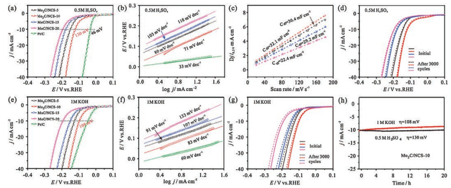
The electrocatalytic performance of Mo2C/NCS-5, Mo2C/NCS- 10, MoC/NCS-15 and MoC/NCS-20 catalysts for HER was investigated in 0.5 mol/L H2SO4 solution. As shown from the polarization curves in Fig. 4a, Pt/C exhibits perfect catalytic performance with nearly zero onset overpotential, and Mo2C/NCS-10 exhibits a higher HER activity as compared with the other three molybdenum carbides catalysts. The overpotential obtained at the current density of 10 mA/cm2 is an important parameter for comparison catalysts in solar hydrogen production [36]. The corresponding overpotentials at a current density of 10 mA/cm2 for Mo2C/NCS-5, Mo2C/NCS-10, MoC/NCS-15 and MoC/NCS-20 are 155 mV, 130 mV, 172 mV and 197 mV, respectively, indicating a faster hydrogen evolution rate on Mo2C/NCS-10 electrode, although it is higher than that of Pt/C (46 mV). Such prominent HER activity of Mo2C/ NCS-10 in acid media is better in the list among the current noble metal-free HER catalysts (Table S4 in Supporting information). The Tafel plot was gained by plotting the logarithm of the kinetic current density obtained from the corresponding HER polarization curves (Fig. 4b). The Tafel slope of Mo2C/NCS-5, Mo2C/NCS-10, MoC/NCS-15 and MoC/NCS-20 is calculated to be 80 mV/dec, 71 mV/dec, 103 mV/dec and 118 mV/dec respectively, indicating a Volmer-Heyrovsky mechanism for HER, and the HER rate is determined by the electrochemical desorption of H and H+ from the catalyst surface to form hydrogen [16]. In addition, the lowest value of Tafel slope for Mo2C/NCS-10 means the excellent HER catalytic activity with increasing potential as compared with other MoxC based catalysts.

|
Download:
|
| Fig. 4. (a) HER polarization curves of Mo2C/NCS-5, Mo2C/NCS-10, MoC/NCS-15 and MoC/NCS-20 in 0.5 mol/L H2SO4 solution. (b) Tafel plots of the corresponding catalysts. (c) Capacitive current at 0.3 V as a function of scan rate for MoxC/NCS. (d) HER polarization curves of Mo2C/NCS-5, Mo2C/NCS-10, MoC/NCS-15 and MoC/NCS-20 before and after 3000 potential cycles in 0.5 mol/L H2SO4 solution. (e) HER polarization curves of Mo2C/NCS-5, Mo2C/NCS-10, MoC/NCS-15 and MoC/NCS-20 in 1 mol/L KOH solution. (f) Tafel plots of the corresponding catalysts. (g) HER polarization curves of Mo2C/NCS-5, Mo2C/NCS-10, MoC/NCS-15 and MoC/NCS-20 before and after 3000 potential cycles in 1 mol/L KOH solution. (h) Current density versus time curves (at a constant potential of 130 mV and 108 mV, respectively) on Mo2C/NCS-10 in 0.5 mol/L H2SO4 and 1 mol/L KOH solution. | |
The nitrogen doped carbon nanosheets and fine MoxC nano-particles could provide more active sites for HER. Besides, the enhanced HER performance of Mo2C/NCS-10 could be attributed to the large electrochemically active surface area (ECSA), which can be derived by calculating the double-layer capacitances (Cdl). The double-layer capacitances were obtained using cyclic voltammo-grams between 0.2V and 0.4 V at scan rates ranging from 20mV/s to 180 mV/s (Fig. S3 in Supporting information). The measured Cdl is 30.4, 32.1, 29.2 and 22.4 mF/cm2 for Mo2 C/NCS-5, Mo2C/NCS-10, MoC/NCS-15 and MoC/NCS-20, respectively (Fig. 4c). It can be seen that the Cdl value of Mo2C/NCS-10 is 1.06, 1.10 and 1.44 times higher than that of Mo2C/NCS-5, MoC/NCS-15 and MoC/NCS-20, indicat ing a relative more quantitive of active sites. The result shows that the larger the specific surface area, the smaller the electrochemical active surface area, which is due to the different N content. Although the specific surface area increased, the N/C ratio decreased with the increase of melamine content (Table S2). The N content would affect the double-layer capacitances. A higher N content could increase the electrochemical active area and active sites. Therefore, N-doped carbon nanosheets, ultrafine MoxC nanocrystallites, mesoporous structure and large electrochemical active surface area work together for the better electrocatalytic HER performance. By comparing the electrochemical property and physical characterization, it is found that Mo2C/NCS catalysts possess superior HER activity to MoC/NCS composites. The stability of MoxC/NCS catalysts were measured by potential cycling for 3000 cycles at a sweep rate of 100 mV/s in 0.5 mol/L H2SO4 solution, as illustrated in Fig. 4d. There is negligible current decay for all as prepared materials, suggesting the excellent electrochemical stability of these catalysts in acid solution.
The HER activity of MoxC/NCS catalysts was also conducted in basic media (1 mol/L KOH). The Mo2C/NCS-10 exhibits better electrocatalytic HER activity in 1 mol/L KOH solution, with an smaller overpotential of 108 mV at the current density of 10 mA/ cm2, compared with Mo2C/NCS-5 (125 mV), MoC/NCS-15 (147 mV) and MoC/NCS-20 (194 mV), as shown in Fig. 4e, demonstrating a faster hydrogen evolution rate on Mo2C/NCS-10 in alkaline. The Tafel slope of Mo2C/NCS-10 in Fig. 4f is calculated to be 83 mV/dec, which is comparable to Pt/C (60 mV/dec), much lower than that of Mo2C/NCS-5 (91 mV/dec), MoC/NCS-15 (107 mV/dec) and MoC/ NCS-20 (133 mV/dec), respectively, indicating a Volmer-Heyrovsky mechanism process. Besides, by comparing the HER performance of recent reported MoxC-based composites in alkaline media, it is also confirmed the good HER activity of the obtained Mo2C/NCS-10 (Table S4). The stability of MoxC/NCS catalysts in alkaline medium was evaluated by potential cycling (3000 cycles) at a sweep rate of 100 mV/s. As can be seen from the polarization curves in Fig. 4g, the Mo2C/NCS-10 catalyst exhibits about 8 mV decay after the 3000 potential cycles in alkaline condition, which is smaller as compared with Mo2C/NCS-5, MoC/NCS-15 and MoC/NCS-20. Furthermore, Current density versus time curves for Mo2C/NCS-10 in both 0.5 mol/L H2SO4 and 1 mol/L KOH solution was conducted at constant potentials of 130 and 108 mV for 20 h, respectively. There is a negligible current decay in 0.5 mol/L h2SO4, while a slight current decrease in 1 mol/L KOH during 20 h testing (Fig. 4h). The electrochemical stability of Mo2C/NCS-10 catalyst in KOH solution is inferior to that in H2SO4, which is probably attributed to the corrosion of carbon support in KOH solution, and the active sites would be detached from the carbon support [45].
In summary, MoxC/NCS catalysts were synthesized through a facile mechanical mixing and subsequent high-temperature treatment strategy. The different structure and grain size of molybdenum carbides are obtained by adjusting the mass ratio of melamine and ammonium molybdate precursors. Mo2 C is gradually converted to MoC with increasing the amount of melamine. The electrochemical performance for HER of these MoxC/NCS composites is investigated in both 0.5 mol/L H2SO4 and 1 mol/L KOH media. The Mo2C/NCS-10 presents a good HER activity, and exhibits a small overpotential of 130 mV in 0.5 mol/L H2SO4 and 108 mV in 1 mol/L KOH for delivering current density of 10 mA/cm2, respectively. The superior HER activity is attributed to the N-doped carbon nanosheets, ultrafine Mo2 C nanoparticles, moderate surface area and mesoporous structure.
AcknowledgmentsThis work was supported by the National Natural Science Foundation (No. 21706086), 1000 Young Talent (to Deli Wang). The authors thank the Analytical and Testing Center of HUST for allowing use its facilities.
Appendix A. Supplementary dataSupplementary material related to this article canbefound, in the online version, at doi:https://doi.org/10.1016/j.cclet.2018.05.009.
| [1] |
J. Zhu, K. Sakaushi, G. Clavel, et al., J. Am. Chem. Soc. 137 (2015) 5480-5485. DOI:10.1021/jacs.5b01072 |
| [2] |
S. Wang, J. Wang, M. Zhu, et al., J. Am. Chem. Soc. 137 (2015) 15753-15759. DOI:10.1021/jacs.5b07924 |
| [3] |
P. Jena, J. Phys. Chem. Lett. 2 (2011) 206-211. DOI:10.1021/jz1015372 |
| [4] |
M.S. Faber, S. Jin, Energy Environ. Sci. 7 (2014) 3519-3542. DOI:10.1039/C4EE01760A |
| [5] |
E.J. Popczun, J.R. McKone, C.G. Read, et al., J. Am. Chem. Soc. 135 (2013) 9267-9270. DOI:10.1021/ja403440e |
| [6] |
J. Yin, Q. Fan, Y. Li, et al., J. Am. Chem. Soc. 138 (2016) 14546-14549. DOI:10.1021/jacs.6b09351 |
| [7] |
X. Yan, L. Tian, X. Chen, J. Power Sources 300 (2015) 336-343. DOI:10.1016/j.jpowsour.2015.09.089 |
| [8] |
C. Wan, B.M. Leonard, Chem. Mater. 27 (2015) 4281-4288. DOI:10.1021/acs.chemmater.5b00621 |
| [9] |
Y.X. Wang, C.F. Liu, M.L. Yang, et al., Chin. Chem. Lett. 28 (2017) 60-64. DOI:10.1016/j.cclet.2016.05.025 |
| [10] |
M. Tavakkoli, T. Kallio, O. Reynaud, et al., Angew. Chem. Int. Ed. 54 (2015) 4535-4538. DOI:10.1002/anie.201411450 |
| [11] |
Z. Huang, Z. Chen, Z. Chen, et al., Nano Energy 9 (2014) 373-382. DOI:10.1016/j.nanoen.2014.08.013 |
| [12] |
X. Yan, L. Tian, M. He, X. Chen, Nano Lett. 15 (2015) 6015-6021. DOI:10.1021/acs.nanolett.5b02205 |
| [13] |
B. Luo, T. Huang, Y. Zhu, D. Wang, J. Energy Chem. 26 (2017) 1147-1152. DOI:10.1016/j.jechem.2017.08.013 |
| [14] |
X. Chen, G. Liu, W. Zheng, et al., Adv. Funct. Mater. 26 (2016) 8537-8544. DOI:10.1002/adfm.v26.46 |
| [15] |
H. Yuan, L. Kong, T. Li, Q. Zhang, Chin. Chem. Lett. 28 (2017) 2180-2194. DOI:10.1016/j.cclet.2017.11.038 |
| [16] |
J. Guo, J. Wang, Z. Wu, et al., J. Mater.Chem. A 5 (2017) 4879-4885. DOI:10.1039/C6TA10758C |
| [17] |
W.F. Chen, C.H. Wang, K. Sasaki, et al., Energy Environ. Sci. 6 (2013) 943-951. DOI:10.1039/c2ee23891h |
| [18] |
C. Wan, Y.N. Regmi, B.M. Leonard, Angew. Chem. Int. Ed. 53 (2014) 6407-6410. DOI:10.1002/anie.201402998 |
| [19] |
H. Ang, H.T. Tan, Z.M. Luo, et al., Small 11 (2015) 6278-6284. DOI:10.1002/smll.201502106 |
| [20] |
M. Fan, H. Chen, Y. Wu, et al., J. Mater. Chem. A 3 (2015) 16320-16326. DOI:10.1039/C5TA03500G |
| [21] |
R. Ma, Y. Zhou, Y. Chen, et al., Angew. Chem. Int. Ed. 54 (2015) 14723-14727. DOI:10.1002/anie.201506727 |
| [22] |
H. Vrubel, D. Merki, X. Hu, Energy Environ. Sci. 5 (2012) 6136-6144. DOI:10.1039/c2ee02835b |
| [23] |
M.A. Lukowski, A.S. Daniel, F. Meng, et al., J. Am. Chem. Soc. 135 (2013) 10274-10277. DOI:10.1021/ja404523s |
| [24] |
D. Voiry, M. Salehi, R. Silva, et al., Nano Lett. 13 (2013) 6222-6227. DOI:10.1021/nl403661s |
| [25] |
T. Wang, K. Du, W. Liu, et al., J. Mater. Chem. A 3 (2015) 4368-4373. DOI:10.1039/C4TA06651K |
| [26] |
Z. Wu, J. Wang, K. Xia, et al., J. Mater. Chem. A 6 (2018) 616-622. DOI:10.1039/C7TA09307A |
| [27] |
H. Vrubel, X. Hu, Angew. Chem. Int. Ed. 51 (2012) 12703-12706. DOI:10.1002/anie.201207111 |
| [28] |
Y. Liu, G. Yu, G.D. Li, et al., Angew. Chem. Int. Ed. 54 (2015) 10752-10757. DOI:10.1002/anie.201504376 |
| [29] |
J. Gao, Z. Cheng, C. Shao, et al., J. Mater. Chem. A 5 (2017) 12027-12033. DOI:10.1039/C7TA03228E |
| [30] |
D.R. Stellwagen, J.H. Bitter, Green Chem. 17 (2015) 582-593. DOI:10.1039/C4GC01831A |
| [31] |
C. Wan, N.A. Knight, B.M. Leonard, Chem. Commun. 49 (2013) 10409-10411. DOI:10.1039/c3cc46551a |
| [32] |
H.B. Wu, B.Y. Xia, L. Yu, X.Y. Yu, X.W. Lou, Nat. Commun. 6 (2015) 6512. DOI:10.1038/ncomms7512 |
| [33] |
H. Ang, H. Wang, B. Li, et al., Small 12 (2016) 2859-2865. DOI:10.1002/smll.201600110 |
| [34] |
T. Meng, L. Zheng, J. Qin, D. Zhao, M. Cao, J. Mater. Chem. A 5 (2017) 20228-20238. DOI:10.1039/C7TA05946A |
| [35] |
L. Liao, S. Wang, J. Xiao, et al., Energy Environ. Sci. 7 (2014) 387-392. DOI:10.1039/C3EE42441C |
| [36] |
D.H. Youn, S. Han, J.Y. Kim, et al., ACS Nano 8 (2014) 5164-5173. DOI:10.1021/nn5012144 |
| [37] |
K. Ojha, S. Saha, H. Kolev, B. Kumar, A.K. Ganguli, Electrochim. Acta 193 (2016) 268-274. DOI:10.1016/j.electacta.2016.02.081 |
| [38] |
T. Asefa, X. Huang, Chem.-Eur. J. 23 (2017) 10703-10713. DOI:10.1002/chem.v23.45 |
| [39] |
S.C. Yan, Z.S. Li, Z.G. Zou, Langmuir 25 (2009) 10397-10401. DOI:10.1021/la900923z |
| [40] |
R. Li, S. Wang, W. Wang, M. Cao, Phys. Chem. Chem. Phys. 17 (2015) 24803-24809. DOI:10.1039/C5CP03890A |
| [41] |
X. Xu, F. Nosheen, X. Wang, Chem. Mater. 28 (2016) 6313-6320. DOI:10.1021/acs.chemmater.6b02586 |
| [42] |
Y.Y. Chen, Y. Zhang, W.J. Jiang, et al., ACS Nano 10 (2016) 8851-8860. DOI:10.1021/acsnano.6b04725 |
| [43] |
H. Lin, Z. Shi, S. He, et al., Chem. Sci. 7 (2016) 3399-3405. DOI:10.1039/C6SC00077K |
| [44] |
Y. Shi, Y. Yang, Y.W. Li, H. Jiao, Catal. Sci. Technol. 6 (2016) 4923-4936. DOI:10.1039/C5CY02008E |
| [45] |
S.E. Jang, H. Kim, J. Am. Chem. Soc. 132 (2010) 14700-14701. DOI:10.1021/ja104672n |