 2019, Vol. 30


Organic light emitting diodes (OLEDs) have been attracting much attention in flat panel displays (FPDs) due to their high brightness, wide viewing angle, low power consumption and good contrast [1-4]. Inkjet printing is considered as one of the most promising technology in the field of controlled deposition of polymers and functional materials in well-defined patterns, especially in relation to the fabrication of multicolor OLED displays [5-12]. For OLED displays, the accuracy and uniformity of organic layer thickness is an important manufacturing issue.
In the thin film forming process, the solutes prefer depositing along the periphery due to the coffee ring effect [13-15]. This phenomenon would affect thickness uniformity of inkjet printed films and further influence the performance of devices. Deegan et al. [16, 17] explained that, when the contact line between a droplet and substrate is pinned, there exist a mismatch between the evaporation of the solvent and the decrease of solution volume. The evaporation rate of the solvent is faster at the pinned threephase contact line, meanwhile the volume decreases occurred mainly in the central region of droplets. Such a mismatch promotes the formation of radial flow from the interior of the drop to the edge. This inside-out radial flow carries the solutes to the contact line and formed ring-like morphology.
To eliminate coffee ring effect and improve film uniformity of inkjet printed films, several methods have been proposed [18-24]. The coffee ring effect can be avoided through weakening the outward flow [20-22], increasing inward Marangoni flow [23-27] or prevent the droplet pinning [28, 29]. Soltman et al. studied the effect of the substrate temperature on the inkjet printed thin film morphology [20]. Morphology adjustment was realized through using cooled substrate to weakened radial capillary flow. Schubert et al. also reported that through utilizing gelation of polymer solution to restrain the coffee ring effect [21]. Lines with improved morphological control and resolution were achieved due to the reduced outward flow. Yodh et al. found that the anisotropic particles can inhibit the coffee ring effect effectively due to the strong long-ranged attractions between ellipsoids [22]. Marangoni flow can be another effective way to suppress the complementary flow and regulate thickness uniformity of inkjet printed films. Hu et al. obtained reversed coffee ring deposition through Marangoni convection induced by temperature gradient [23]. Marangoni flow also can be produced with the concentration gradient through adding compositional solvent. Moon et al. fabricated homogeneous conductive patterns by adding co-solvent with high boiling point and low surface tension [25]. Pinned contact line is a primary requirement for the coffee ring effect to take place, thus coffee rings can be avoided with the depinned three phase contact line [30]. For inkjet printed OLEDs, through modulation of the solvent properties to eliminate the coffee rings maybe most promising.
In this paper, film forming property of poly(spirobifluorene) solutions inkjet printed on substrate with low surface energy separators was investigated. Through adding co-solvent with high boiling point and high viscosity to reduce the capillary force of radial flow, poly (spirobifluorene) films with improved thickness uniformity were obtained due to the inhibition of coffee ring effect. Through modulation of the volume fraction of co-solvent, the thickness of inkjet printed films can be tuned effectively. Such inkjet printed poly(spirobifluorene) films are ideal for PLED fabrication and could gain improved device performance. Passive matrix display has been fabricated and the performance of the matrix was characterized.
Isopropylbenzene (IPB) and chlorobenzene (CB) were selected as main solvent due to their good solubility to poly(spirobifluorene) and stable inkjet property. Poly(spirobifluorene) was dissolved in pure CB or IPB and inkjet printed on the prefabricated PEDOT: PSS films inkjet printed previously under the confinement of the low surface energy separators. Figs. 1a and c show the fluorescence images of poly(spirobifluorene) film deposited from pure IPB and CB solutions, the deposited films show heavy edge deposition phenomena. Main poly(spirobifluorene) were deposited at the edge region of the grooves and the fluorescences were asymmetric. The thickness uniformity of the inkjet printed poly (spirobifluorene) films were poor due to the coffee ring effect.

|
Download:
|
| Fig. 1. The fluorescence images of poly(spirobifluorene) films deposited from (a) CB, (b) CB/CHB (60/40), (c) IPB and (d) IPB/CHB (60/40). The width of groove and separator is 200 μm and 50 μm, respectively. | |
In order to improve the uniformity of the inkjet printed film, cosolvent with high boiling point and high viscosity was mixed with main solvent and their effects on film uniformity were investigated. Here we choose cyclohexylbenzene (CHB) as the co-solvent. The main physical parameters of IPB, CB and CHB are listed in Table 1. Figs. 1b and d show the fluorescence images of poly (spirobifluorene) films inkjet printed from CB/CHB (60/40) and IPB/ CHB (60/40) solutions, respectively. Uniformity of inkjet printed poly(spirobifluorene) films improved dramatically with the addition of co-solvent CHB. The addition of CHB did not influence the morphology of printed film obviously (AFM images shown in Fig. S2 in Supporting information). Figs. S3 and S4 (Supporting information) show the optical images and corresponding fluorescence images of poly(spirobifluorene) films inkjet printed from IPB/CHB and CB/CHB solutions with different volume fraction of CHB.
|
|
Table 1 Main physical parameters, including boiling point (b.p.), viscosity (η), surface energy (γ), saturated vapor pressure (PV). |
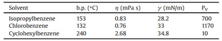
From the cross-section profiles of poly(spirobifluorene) films deposited from IPB/CHB and CB/CHB solvent mixtures, we can see the improvement of film thickness uniformity more obviously. For pure IPB solution, the poly(spirobifluorene) film was about 50 nm and more than 120 nm at the center and edge regions respectively. As for IPB/CHB solvent mixtures with volume fraction of 90/10, edge deposition phenomenon is suppressed mostly. The difference of film thickness between the edge and the center region of the film reduced to about 15 nm. With further increasing the volume fraction of CHB, the thickness uniformity further increased to less than 10 nm. These results indicate that the coffee ring effect has been restrained. When the volume fraction of CHB increased to 50%, there is convex–lens like cross-section at the center region for poly(spirobifluorene) film maybe due to the excess of CHB. For CB/ CHB solvent mixtures, the thickness fluctuation reduced from over 100 nm to about 10 nm (Fig. 2d). The addition of CHB suppressed the outer-flow and edge deposition and increased the average thickness uniformity.

|
Download:
|
| Fig. 2. The cross-section profiles of poly(spirobifluorene) films deposited from (a) IPB/CHB and (b) the corresponding thickness fluctuation, (c) CB/CHB solvent mixtures with different volume fraction of CHB and (d) the corresponding thickness fluctuation. | |
In the solvent evaporation process, fast solvent evaporation can induces fast diffusion of the polymer solute and results in maximizes material transfer toward the edges. It is the driving force of complementary flow via capillarity. Meanwhile, the viscosity of the solution can hamper such transfer; it is the resistance of the radial flow. Based on the data in Table 1, the Pv of CHB is 10, which is much lower than IPB and CB. Meanwhile, the η of CHB is higher than IPB and CB. With the increase of CHB content, Pv and η of solvent mixtures showing a tendency to decrease and increase, respectively. For pure IPB or CB, the fast solvent evaporation speed during inkjet printing facilitates the transfer of poly(spirobifluorene) in films. Meanwhile, the lower viscosity of the solution can not reduce such radial flow effectively. Poly (spirobifluorene) films with heavy coffee ring effect can be obtained. When adding co-solvent CHB with high boiling point and high viscosity, the driving force of radial flow is reduced due to the low evaporation rate of CHB. Meanwhile, the high viscosity of CHB increases the resistance of the radial flow. By adjusting the composition of co-solvent, to tune the volatility/viscosity match, we can realize the inhibition of edge deposition in the inkjet printing process and gain films with uniform thickness.
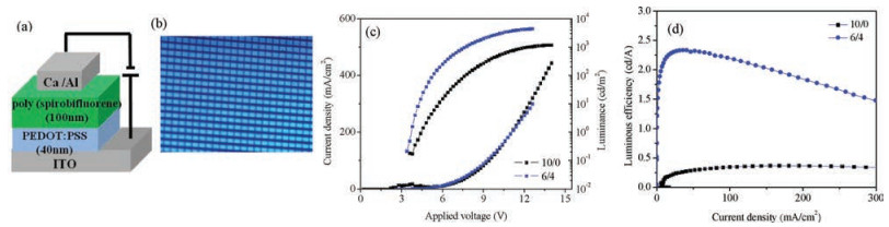
The poly(spirobifluorene) films patterned by inkjet printing were used to fabricate PLEDs. The device structure of the PLEDs is ITO/PEDOT:PSS/poly(spirobifluorene)/Ca/Al (Fig. 3a). ITO stripes have a width of 200 mm with a space of 50 mm patterned by photolithography and wet-etching were used as anode. Low energy separators have a width of 50 mm with a space of 200 mm vertical with the ITO stripes were used as confined pattern. The size of each pixel was 200 × 200 μm. The films of PEDOT:PSS were inkjet printed on the substrate with the low surface energy separators firstly. Then the poly (spirobifluorene) films were deposited on the PEDOT:PSS film by inkjet printing from IPB/CHB (60/40) or IPB solution and served as emitting layer. A thin layer of calcium (20 nm)/aluminum (100 nm) were deposited through physics vapor deposition.

|
Download:
|
| Fig. 3. (a) Device configuration, (b) optical image of matrix of inkjet printed PLEDs, (c) current density-voltage-luminance curves and (d) their current density dependence of luminous efficiency of devices inkjet printed with pure IPB and IPB/CHB (60/40) solution. | |
The optical images of the inkjet printed pixel array from IPB/ CHB (60/40) solution are shown in Fig. 3b. All the pixels are similar to each other in the whole and the light-emitting intensity in every pixel is uniform. Figs. 3c and d show the current density-voltageluminescence characteristics and current density dependence of luminous efficiency of devices inkjet printed with pure IPB and IPB/ CHB (60/40) solution. By improving the uniformity of the film thickness, device with improved performance can be obtained. For devices inkjet printed from IPB/CHB (60/40) solution, the turn-on voltage is 3.7 V, the maximum luminance is 4400 cd/m2 and the maximum luminous efficiency is 2.33 cd/A. While the performance of the devices inkjet printed from pure IPB is much lower. The turnon voltage is 4.6 V, the maximum luminance is 1160 cd/m2 and the maximum luminous efficiency is 0.37 cd/A.
We further compared the performance of the devices inkjet printed from IPB/CHB (60/40) solution and CB/CHB (60/40) solution with the device fabricated by spin coating [31]. The corresponding device data are summarized in Table S1 in Supporting information. The CIE of devices inkjet printed from IPB/CHB (60/40) solution and CB/CHB (60/40) solution is comparable with device fabricated by spin coating. The maximum luminous efficiency of devices inkjet printed with poly (spirobifluorene) from IPB/CHB (60/40) can reach 80% of the spin-coated devices [31]. The maximum luminous efficiency of devices inkjet printed from CB/CHB (60/40) solution is relative lower maybe due to the presence of halogen ions in chlorobenzene solvents.
In conclusion, we have improved the thickness uniformity of inkjet printed poly(spirobifluorene) films through adding cosolvent with lower volatility and higher viscosity. Coffee ring effect can be overwhelmed through modulated the volatility/viscosity match to regulate the driving force and the resistance for evaporation-driven radial flow during the evaporation process. By improving the uniformity of the film thickness, device with improved performance can be obtained. The maximum luminous efficiency of devices with inkjet printed poly(spirobifluorene) can reach 80% of the spin-coated devices.
AcknowledgmentsThis work was financially supported by the National Natural Science Foundation of China (Nos. 21574130, 51473161, 51873212), the Ministry of Science and Technology of China (No. 2015CB655001) and National Key R&D Program of "Strategic Advanced Electronic Materials" (Nos. 2016YFB0401301, 2016YFB0401100).
Appendix A. Supplementary dataSupplementarymaterial related to this article canbefound, in the online version, at doi:https://doi.org/10.1016/j.cclet.2018.09.007.
| [1] |
C.W. Tang, S.A. Vanslyke, Appl. Phys. Lett. 51 (1987) 913-915. DOI:10.1063/1.98799 |
| [2] |
S.A. Van Slyke, C.H. Chen, C.W. Tang, Appl. Phys. Lett. 69 (1996) 2160.
|
| [3] |
Y. Sun, N.C. Giebink, H. Kanno, et al., Nature 440 (2006) 908-912. DOI:10.1038/nature04645 |
| [4] |
K.S. Yook, J.Y. Lee, Adv.Mater. 26 (2014) 4218-4233. DOI:10.1002/adma.v26.25 |
| [5] |
M. Liu, J.X. Wang, M. He, et al., ACS Appl. Mater. Interfaces 6 (2014) 13344-13348. DOI:10.1021/am5042548 |
| [6] |
S.C. Chang, J. Liu, J. Bharathan, et al., Adv. Mater. 14 (1999) 734-737. |
| [7] |
T. Shimoda, K. Morii, S. Seki, H. Kiguchi, MRS Bull. 28 (2003) 821-827. DOI:10.1557/mrs2003.231 |
| [8] |
Q.L. Niu, Y.X. Shao, W. Xu, et al., Org. Electron. 9 (2008) 95-100. |
| [9] |
H.S. Lee, J.B. Yoon, J. Micromech. Microeng. 15 (2005) 2136-2140. DOI:10.1088/0960-1317/15/11/020 |
| [10] |
Z.H. Du, X.H. Yu, Y.C. Han, Chin. Chem. Lett. 29 (2018) 399-404. DOI:10.1016/j.cclet.2017.09.031 |
| [11] |
H. Zheng, Y. Zheng, N.L. Liu, et al., Nat. Commun. 4 (2013) 1971.
|
| [12] |
J.Z. Sun, Y.Z. Guo, B. Cui, et al., Appl. Surf. Sci. 445 (2018) 391-397. DOI:10.1016/j.apsusc.2018.03.204 |
| [13] |
R.D. Deegan, O. Bakajin, T.F. Dupont, et al., Nature 389 (1997) 827-829. DOI:10.1038/39827 |
| [14] |
M. Kuang, L.B. Wang, Y.L. Song, Adv. Mater. 26 (2014) 6950-6958. DOI:10.1002/adma.v26.40 |
| [15] |
Y.M. Lin, Y. Qu, X.H. Yu, Y.C. Han, Chin. J. Appl. Chem. 35 (2018) 129-136. |
| [16] |
R.D. Deegan, O. Bakajin, T.F. Dupont, et al., Phys. Rev. E 62 (2000) 756-765. DOI:10.1103/PhysRevE.62.756 |
| [17] |
R.D. Deegan, Phys. Rev. E 61 (2000) 475-485. DOI:10.1103/PhysRevE.61.475 |
| [18] |
J.Z. Sun, B. Bao, M. He, H.H. Zhou, Y.L. Song, ACS Appl. Mater. Interfaces 7 (2015) 28086-28099. DOI:10.1021/acsami.5b07006 |
| [19] |
M. Anyfantakis, D. Baigl, ChemPhysChem 16 (2015) 2726-2734. DOI:10.1002/cphc.v16.13 |
| [20] |
D. Soltman, V. Subramanian, Langmuir 24 (2008) 2224-2231. DOI:10.1021/la7026847 |
| [21] |
A.M.J. van den Berg, A.W.M. de Laat, P.J. Smith, J. Perelaera, U.S. Schubert, J. Mater. Chem. 17 (2007) 677-683. DOI:10.1039/B612158F |
| [22] |
P.J. Yunker, T. Still, M.A. Lohr, A.G. Yodh, Nature 476 (2011) 308-311. DOI:10.1038/nature10344 |
| [23] |
H. Hu, R.G. Larson, J. Phys. Chem. B 110 (2006) 7090-7094. DOI:10.1021/jp0609232 |
| [24] |
T. Still, P.J. Yunker, A.G. Yodh, Langmuir 28 (2012) 4984-4988. DOI:10.1021/la204928m |
| [25] |
D. Kim, S. Jeong, B.K. Park, J. Moon, Appl. Phys. Lett. 89 (2006) 264101.
|
| [26] |
E. Tekin, B.J. de Gans, U.S. Schubert, J. Mater. Chem. 14 (2004) 2627-2632. DOI:10.1039/b407478e |
| [27] |
R.B. Xing, T.L. Ye, Y. Ding, et al., Chin. J. Chem. 31 (2013) 1449-1454. DOI:10.1002/cjoc.v31.11 |
| [28] |
H.B. Eral, D.M. Augustine, M.H.G. Duits, F. Mugele, Soft Matter 7 (2011) 4954-4958. DOI:10.1039/c1sm05183k |
| [29] |
L.Y. Cui, J.H. Zhang, X.M. Zhang, et al., ACS Appl. Mater. Interfaces 4 (2012) 2775-2780. DOI:10.1021/am300423p |
| [30] |
B.J. de Gans, U.S. Schubert, Langmuir 20 (2004) 7789-7793. DOI:10.1021/la049469o |
| [31] |
X.C. Wang, L. Zhao, S.Y. Shao, et al., Macromolecules 47 (2014) 2907-2914. DOI:10.1021/ma500407m |