 2018, Vol. 29


b Key Laboratory for Renewable Energy, Beijing Key Laboratory for New Energy Materials and Devices, Beijing National Laboratory for Condensed Matter Physics, Institute of Physics, Chinese Academy of Sciences, Center of Materials Science and Optoelectronics Engineering, University of Chinese Academy of Sciences, Beijing 100190, China
With the growing demand for the higher energy density of lithium-ion batteries (LIBs), the anionic redox reaction (ARR), which could further improve the capacity even beyond the theoretical capacity based on the transition metal redox, has become a hot topic in recent years. Lithium-rich materials, delivering the capacity even more than 300 mAh/g, are the most representative cathode materials taken advantage of ARR during initial de-lithiation [1-3]. The long plateau during the initial delithiation at ~4.5 V is the typical electrochemical behavior of ARR for lithium-rich cathodes [1]. However, the irreversibility of ARR in most lithium-rich materials with only 3d transition metals hinders their application. The origin of the irreversibility is due to the irreversible phase transition from layered to spinel phase caused by the migration of transition metals [4]. In contrast, materials with 4d or 5d transition metals, offering stronger M—O bonds to stabilize the oxidized oxygen species, have relatively better ARR reversibility [5, 6]. In the case of Na-ion batteries (NIBs), which have attracted great attention for large-scale energy storage [7-9], ARR is also found in many layered oxide cathode materials, such as, P2-type Na5/6[Li0.25Mn0.75]O2, P2-type Na0.67[Mg0.28Mn0.72]O2 reported by Komaba et al. [10, 11], P3-type Na0.6[Li0.2Mn0.8]O2 reported by Goodenough et al. [12, 13], P2-type Na0.6[Li0.2Mn0.8]O2 reported by Nazar et al. [14], P2-type Na0.78[Ni0.23Mn0.69]O2 reported by Meng et al. [15], Na-rich Na2[Ru1-ySny]O3 and Na2IrO3 reported by Tarascon et al. [16, 17]. To be noticed that the oxygen redox behavior in NIBs is different from that in LIBs, for some of the materials with only 3d transition metals have highly reversible ARR behavior [10, 12]. However, the present materials are still not enough for researchers to fully understand the ARR mechanism. One significant reason is that most synthesized materials, such as Na5/6[Li0.25Mn(Ⅲ)0.08Mn(Ⅳ)0.67]O2 and Na0.67[Mg0.28Mn(Ⅲ)0.11Mn (Ⅳ)0.61]O2, contain both Mn3+ and Mn4+, which will make the study of charge compensation more complicated as Mn3+ will also participate in the first initial charge process. Here, a layered oxide Na0.6[Mg(Ⅱ)0.3Mn(Ⅳ)0.7]O2 with only Mg2+ and Mn4+ in the transition metal layer is synthesized and investigated. The Mg2+ and Mn4+ are always considered unable to be further oxidized [13], thus oxygen should be the only element that possibly participates in the charge compensation process for the initial charge.
P2-type Na0.6[Mg0.3Mn0.7]O2 was prepared by a solid-state reaction using precursors of Na2CO3 (99.9%, Alfa), MgO (99%, Alfa), MnO2 (99.9%, Alfa), and 2% more Na2CO3 was used for the compensation of volatilization loss during high temperature. Then the mixture was heated at 700 ℃ for 24 h in air and then naturally cooled to room temperature.
The structure was characterized using an X-ray diffractometer (XRD) (D8 Bruker) with Cu-Kα radiation (λ = 1.5405 Å) in the scan range (2θ) of 10°-80°. The morphologies of the samples were investigated by scanning electron microscopy (SEM) in combination with energy-dispersive X-ray spectroscopy (EDS)- mapping (Hitachi-S4800). The specific ratios of Na, Mg and Mn in the samples were measured by inductively coupled plasma atomic emission spectrometry (ICP-AES).
All the electrochemical tests were conducted using coin cells (CR2032), assembled in an argon filled glove-box. The working electrode was prepared by rolling out the mixture of active material (80 wt%), Super P (15 wt%) and polytetrafluoroethylene (PTFE 5 wt%) into thin films, followed by cutting into equal-area pieces and drying at 120 ℃ in vacuum for 10 h. The loading mass of active material on positive electrode was controlled to 6.0-7.0mg/cm2. The electrolyte wasa solutionof1 mol/LNaClO4 inethylene(EC), dimethyl carbonate (DMC), propylene carbonate (PC) (1:1:1 in volume) and fluoroethylene carbonate (FEC) (2% involume). Sodium foil was used as the counter electrode and glass fiber was used as the separator. The charge and discharge tests were carried out using a Land CT2001 A battery test system (Wuhan, China) in a voltage range of 1.5-4.4 V at various C-rates at room temperature.
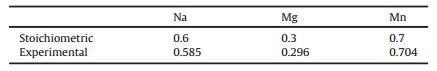
The XRD pattern of the as-prepared material is shown in Fig. 1a. Na0.6[Mg0.3Mn0.7]O2 is crystallized in P2 phase, similar to previously reported P2-Na0.67[Mg0.28Mn0.72]O2, in which sodium ions are accommodated between MO2 slabs as shown in Fig. 1a. All the diffraction peaks can be indexed to a hexagonal lattice with space group of P63/mcm, where the (100) and (102) peaks are superlattice line, suggesting the formation of in-plane ordering between Mg2+ and Mn4+. The SEM image in Fig. 1b shows that the crystallites of the compound are highly agglomerated with a wide size range of irregular particles.

|
Download:
|
| Fig. 1. Crystal structure and particle morphology. (a) X-ray diffraction pattern and (b) typical SEM image of as-prepared Na0.6[Mg0.3Mn0.7]O2 sample. | |
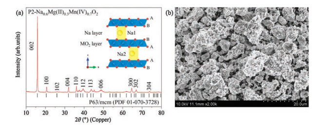
The quantitative analysis of the as-prepared Na0.6[Mg0.3Mn0.7] O2 sample was then carried out using ICP-AES, and the results are shown in Table 1. The experimental value is in good agreement with the designed stoichiometric of Na0.6[Mg0.3Mn0.7]O2, thus confirming that the valence of almost all manganese in the compound is +4. EDS mapping of Na0.6[Mg0.3Mn0.7]O2 was also conducted to confirm the elemental distribution. The elemental mappings of Na, Mg, and Mn are displayed in Fig. 2, exhibiting a uniform distribution of sodium, magnesium, and manganese in the sample.
|
|
Table 1 Results of ICP-AES analysis of Na0.6[Mg0.3Mn0.7]O2 compound where Mg + Mn was normalized to be unity. |

|
Download:
|
| Fig. 2. EDS mapping of Na0.6[Mg0.3Mn0.7]O2 sample. (a) SEM image; (b–d) corresponding elemental mapping of the Na, Mg, and Mn elements, respectively, with the selected area marked by the yellow rectangle in (a). | |
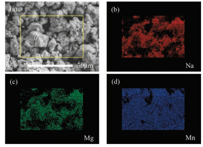
The electrochemical performance of the Na0.6[Mg0.3Mn0.7]O2 electrode was evaluated in sodium half cells at room temperature. Fig. 3a shows galvanostatic charge (Na deintercalation)/discharge (Na intercalation) curves of the first 20 cycles in the voltage range of 1.5-4.4 V versus Na+/Na at a current rate of 0.05C (10 mA/g). The initial charge capacity is ~130 mAh/g, showing a long plateau at ~4.2 V, corresponding to 0.44 e- transfer. The initial discharge capacity is ~210 mAh/g, corresponding to 0.72 e- transfer, with the average storage voltage of 2.5 V for the first discharge. The Coulombic efficiency of the second cycle is 97.9% and then increases to ~99.5% in the following cycles. The overall electrochemical behavior of Na0.6[Mg0.3Mn0.7]O2 is alike with that of Na5/6[Li0.25Mn0.75]O2 and Na2/3[Mg0.28Mn0.72]O2. For the initial charge, there is not a strong evidence so far to prove that Mn4+ can be further oxidized to Mn5+ in NIBs, thus indicating the 4.2 V voltage plateau during the initial charge is probably induced by ARR. The long slope region during discharge involves both ARR (partly reversible) and Mn redox reaction (Mn4+ → Mn3+) at lower voltage. For the following cycles, the 4.2 V voltage plateau still exists, indicating the oxygen redox is reversible. Notable voltage hysteresis of the material is observed after the initial charge, which is a typical character of many Li-rich materials with 3d transition metals [4-6].

|
Download:
|
| Fig. 3. Electrochemical performance of Na0.6[Mg0.3Mn0.7]O2. (a) The charge-discharge curves; (b) capacity & Coulombic efficiency Na0.6[Mg0.3Mn0.7]O2versus cycle number at a current rate of 0.05C in the voltage range of 1.5–4.4 V versus Na+/Na; and (c) rate capability of Na0.6[Mg0.3Mn0.7]O2. | |
Cycling and rate performance are also tested in half-cells with Na metal as the negative electrode. After 50 cycles, the capacity retention is only ~50% with Coulombic efficiency values scatted after ~40 cycles, which is a sign of electrolyte decomposition and drying up and indicates the severe side-reaction at electrode/electrolyte interface [13]. Rate capability of Na0.6[Mg0.3Mn0.7]O2 is tested from 1/20C to 2C and the corresponding specific discharge capacities are 212 mAh/g, 196 mAh/g, 156 mAh/g, 110 mAh/g and 52 mAh/g. With the increase of C-rate, voltage hysteresis becomes severer and ARR plateau degenerates obviously. The inferior rate capability could be related to the sluggish kinetics of ARR. Effective strategies should be further explored to solve problems of these type materials.
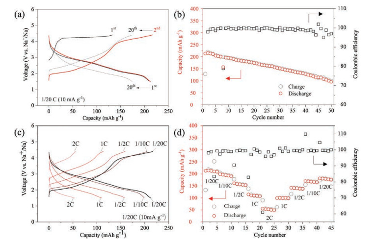
The differential capacity curves of the first and second cycle are shown in Fig. 4. There are two pairs of oxidation/reduction peaks: the first pair at 4.2 V/2.8 V and the second pair at 2.0 V/2.0 V. The first pair of oxygen redox shows large polarization, which is similar to the phenomenon in Li-air batteries, while the second Mn4+/Mn3+ redox pair displays small polarization. The other small peaks could be caused by the Na/vacancy ordering, which is usually found in many manganese-based NIB materials. Notably, there is only one peak in the first charge process, once again confirming that only oxygen redox participates into the charge compensation mechanism. In the second cycle the oxygen redox peak shifts slightly to lower voltage, which might be caused by the involvement of Mn4+/Mn3+ redox during the second charge process, indicating that the Jahn-Teller distortion introduced by Mn3+ could have subtle effects on the ARR activity and its reversibility.

|
Download:
|
| Fig. 4. Differential capacity curves of the first and second cycles of the Na0.6[Mg0.3Mn0.7]O2 electrode. | |
In conclusion, a P2-type layered oxide only containing Na+, Mg2+, Mn4+ and O2- has been synthesized and investigated as cathode for NIBs. The Mg2+ and Mn4+ are always considered unable to be further oxidized, thus the charge compensation should be contributed by ARR itself during the initial charge. In the first charge, a long voltage plateau at ~4.2 V with a capacity of ~130 mAh/g is observed. In the following cycles, both oxygen and manganese redox pairs participate in the electrochemical process with a reversible capacity of ~210 mAh/g, and the oxygen redox behavior is found to be highly reversible. The simple elementary composition and highly reversible oxygen redox behavior make Na0.6[Mg0.3Mn0.7]O2 a suitable model material for the further investigation of reversible oxygen redox mechanism in NIBs.
AcknowledgmentThis work was supported by funding from Science and Technology Project of the State Grid Corporation of China ("research on key technology of low-strain layered oxides for long-life Na-ion batteries", No. DG71-16-027).
| [1] |
J. Yan, X. Liu, B. Li, RSC Adv. 4 (2014) 63268-63284. DOI:10.1039/C4RA12454E |
| [2] |
J. Hong, H. Gwon, S.K. Jung, K. Ku, K. Kang, J. Electrochem. Soc. 162 (2015) A2447-A2467. DOI:10.1149/2.0071514jes |
| [3] |
J.W. Choi, D. Aurbach, Nat. Rev. Mater. 1 (2016) 16013. DOI:10.1038/natrevmats.2016.13 |
| [4] |
C. Zhao, Q. Wang, Y. Lu, et al., J. Phys. D-Appl. Phys. 50 (2017) 183001. DOI:10.1088/1361-6463/aa646d |
| [5] |
M. Sathiya, G. Rousse, K. Ramesha, et al., Nat. Mater. 12 (2013) 827-835. DOI:10.1038/nmat3699 |
| [6] |
E. McCalla, A.M. Abakumov, M. Saubanère, et al., Science 350 (2015) 1521-1516. DOI:10.1126/science.aac9715 |
| [7] |
Y. Li, Y. Lu, C. Zhao, et al., Energy Storage Mater. 7 (2017) 130-151. DOI:10.1016/j.ensm.2017.01.002 |
| [8] |
C. Zhao, Q. Wang, Y. Lu, et al., Sci. Bull. 63 (2018) 1125-1129. DOI:10.1016/j.scib.2018.07.018 |
| [9] |
Y. Lu, C. Zhao, X. Qi, et al., Adv. Energy Mater. (2018) 1800108. |
| [10] |
N. Yabuuchi, R. Hara, K. Kubota, et al., J. Mater. Chem. A 2 (2014) 16851-16855. DOI:10.1039/C4TA04351K |
| [11] |
N. Yabuuchi, R. Hara, M. Kajiyama, et al., Adv. Energy Mater. 4 (2014) 1301453. DOI:10.1002/aenm.201301453 |
| [12] |
K. Du, J. Zhu, G. Hu, et al., Energy Environ. Sci. 9 (2016) 2575-2577. DOI:10.1039/C6EE01367H |
| [13] |
X. Rong, J. Liu, E. Hu, et al., Joule 2 (2017) 125-140. |
| [14] |
E. de la Llave, E. Talaie, E. Levi, et al., Chem. Mater. 28 (2016) 9064-9076. DOI:10.1021/acs.chemmater.6b04078 |
| [15] |
C. Ma, J. Alvarado, J. Xu, et al., J. Am. Chem. Soc. (2017) 4835-4845. |
| [16] |
A.J. Perez, D. Batuk, M. Saubanère, et al., Chem. Mater. 28 (2016) 8278-8288. DOI:10.1021/acs.chemmater.6b03338 |
| [17] |
P. Rozier, M. Sathiya, A.R. Paulraj, et al., Electrochem. Commun. 53 (2015) 29-32. DOI:10.1016/j.elecom.2015.02.001 |