 2018, Vol. 29


 ,
Yuxuan Houb,
Shaofei Zhanga,
Guoliang Zhanga,
Ming Lid,
Huanming Lud,
Yong Lid,
Xuerong Zhenge,
Zhijun Qiaob,
Zhenyang Yub,
Qin Huanga,c,
Jianli Kanga,c,f,*
,
Yuxuan Houb,
Shaofei Zhanga,
Guoliang Zhanga,
Ming Lid,
Huanming Lud,
Yong Lid,
Xuerong Zhenge,
Zhijun Qiaob,
Zhenyang Yub,
Qin Huanga,c,
Jianli Kanga,c,f,*
b School of Mechanical Engineering, Tianjin Polytechnic University, Tianjin 300387, China;
c Tianjin Municipal Key Laboratory of Advanced Fibers and Energy Storage, Tianjin 300387, China;
d Test Center, Ningbo Institute of Material Technology and Engineering, Chinese Academy of Science(CAS), Ningbo 315201, China;
e School of Materials Science and Engineering, Key Laboratory of Advanced Ceramics and Machining Technology of Ministry of Education, Tianjin University, Tianjin 300072, China;
f State key laboratory of separation membrane and membrane processes, Tianjin Polytechnic University, Tianjin 300387, China
Rechargeable lithium-ion batteries (LIBs) are profoundly dominating human daily life among the energy storage systems [1-3]. Currently, LIBs are the most promising power sources for environmentally friendly applications, such as electric vehicles (EVs) and hybrid electric vehicles (HEVs) [4-6]. The inherent limitations of commercial batteries, however, can hardly satisfy the increasing social demands today [7]. A world wide effort is being made to develop novel electrode materials for high electrochemical performance LIBs [8, 9].
As an alternative anode material, tin dioxide (SnO2) has exhibited a series of desirable properties, such as alloying/dealloying mechanism, abundant storage, and high theoretical specific capacity (1494 mAh/g, four times commercial graphite) [10-12]. And yet it suffers from poor conductivity and huge volume change during the Li+ intercalation/deintercalation reactions, which are the critical factors that hinder the far-ranging application. Generally, the lithiation reaction is included two steps [13, 14]:

|
(1) |

|
(2) |
The first conversion reaction provides a capacity of 731 mAh/g and the second alloy reaction with a capacity of 763 mAh/g. The Reaction (1) attributes to the poor irreversibly capacity during the first discharge/charge process. The cycling performance of SnO2 anodes is fast fading, which is the huge volume change and pulverization corresponding to Reaction (2) [10-13]. Many researchers have been devoted to overcome these issues. The strategy of synthesizing SnO2 nanostructure, including nanoparticles, nanowires, nanobelts and nanotubes, has been reported by numerous groups [15-19]. And the SnO2/carbon composite is regarded as an effective method, such as introducing carbon nanotubes (CNT), graphene and amorphous carbon as the volumetric buffer layer [20-25]. Hu et al. reported the Cu6Sn5 (core) @SnO2-C (shell) nanocomposite which shows a high performance of 619 mAh/g after 500 cycles [26]. He et al. utilized SiO2 to cover the SnO2/graphene layer for the anode material and the electrode exhibited excellent electrochemical stability of 1950 mAh/g after 1000 cycles [27]. Zu et al. controlled the coated carbon content (4.83%) of SnO2 and prepared the triple-shelled hollow superstructures (TSHSs) which maintained a reversible capacity of 1099 mAh/g over 1450 discharge-charge process [28].
Herein, we design a novel Cu-SnO2 composite derived from Cu6Sn5 alloy, retaining high conductivity of Cu and high theoretical capacity of SnO2 (Fig. S1 in Supporting information)). Cu6Sn5 alloy exhibits excellent conductivity and good electrochemical performance, however, it shows a low theoretical capacity (605 mAh/g) compared with SnO2 [29, 30]. The theoretical capacity of Cu-SnO2 based on Cu6Sn5 alloy can be calculated, which is 995 mAh/g. Kepler prepared the Cu6Sn5 through ball milling in 1999 [31]. It is now widely known that ball milling process is simple [32, 33], which also could be obtained batches of Cu6Sn5 alloy powder. In this paper, Cu6Sn5 alloy was prepared by ball milling. Following, with oxidation and selective reduction process, we synthesized CuSnO2 anode materials. After oxidizing the as-prepared Cu6Sn5 powder, the formed SnO2 can provide high capacity and CuO shows low capacity and poor conductivity [34]. Cu-SnO2 composite, with 6:5 molar ratio ratio of Cu:Sn, is easily achieved through reducing the CuO in CuO-SnO2 with H2 atmosphere selectively. SnO2 is hardly reduced at corresponding to condition. The as-prepared Cu-SnO2 composite shows a high capacity (536.1 mAh/g) at a current density of 100 mAh/g after 200 cycles.
The synthesis process of the Cu-SnO2 composites is briefly described in Fig. S1. There are three steps to fabricate the highperformance LIBs anode materials. Firstly, we prepared Cu6Sn5 alloy by a simply ball milling of the Cu (particle size 1 μm) together with Sn (particle size 3 μm) in an atomic ratio of 6:5 for 50 h, and then the alloy powder was heating at 600 ℃, 700 ℃ and 800 ℃ for 2 h in air, which ascribe to achieve CuO-SnO2 composites powder. In order to convert the CuO into Cu after oxidation reaction, we controlled reduction temperature to adjust the phase compositions and selected the calcining conditions with 200 ℃, 250 ℃ and 300 ℃, respectively in 5 vol% H2/Ar atmosphere. The as-prepared samples characterization and electrochemical measurements are attached in Supporting information.
In order to explore the optimal oxidation temperature, heat treatment, with 600 ℃, 700 ℃ and 800 ℃ in air atmosphere, was performed on the Cu6Sn5 alloy powder. Cu6Sn5 (JCPDS No. 45-1488) and SnO (JCPDS No. 72-1012) phrases are existed in the oxidized composite at 600 ℃ (Fig. 1a). With the oxidized temperature rising, the Cu6Sn5 and SnO peaks are gradually decreased, until to vanish at 800 ℃. As is shown in Fig. 1a, Cu6Sn5 alloy are entirely transformed into SnO2 (JCPDS No. 41-1445) and CuO (JCPDS No. 48-1548) when the oxidized temperature reached to 800 ℃. Furthermore, the different reduction temperatures are also enforced to acquire Cu-SnO2 composite in Fig. 1b. To maintain small crystal sized and well oxidation state, 700 ℃ oxidation temperature is used during oxidized process, and reduction temperature is selected 200 ℃, 250 ℃, 300 ℃, respectively. Reducing temperature with 200 ℃ and 250 ℃, the XRD patterns showed similar phases that the major peaks are SnO2 and Cu. While Cu (111) peak at 2θ = 42° is broader that means the increasing of copper crystal size when reduced temperature increasing to 300 ℃. As can be seen from Fig. 1, Cu-SnO2 composites can be acquired with well crystallized SnO2 and fine Cu crystal when the calcined condition is oxidized at 700 ℃ and reduced at 250 ℃.

|
Download:
|
| Fig. 1. XRD patterns of (a) Cu6Sn5 with different calcining temperature at air atmosphere, and (b) Cu6Sn5 with the oxidation temperature of 700 ℃ and different reduction temperature at 5 vol% H2/Ar atmosphere. | |
The morphologies of Cu-SnO2 composites were analyzed with SEM and EDX mapping results (Figs. S2 and S3 in Supporting information). TEM investigations further revealed that the nanosized SnO2 particles are uniformly dispersed in 3D metal cluster and numerous nanovoids exist in the Cu-SnO2 particle, mostly due to the volume shrink during reduction and recrystallization of CuO (Figs. 2a and b). The nanovoids are extremely favorable for tolerating the large volume change during lithium alloying/ dealloying reactions. In Fig. 2c, HRTEM image shows the (110) and (111) lattice fringes, with the d-spacing measured to be 0.338 nm and 0.202 nm, corresponding to the SnO2 and Cu crystal structures. Meanwhile, the selected area electron diffraction (SAED) pattern (Fig. 2d) shows two sets of polycrystalline diffraction discontinuous rings: 1) SnO2 phase can be indexed as (110) and (101); 2) Cu phase can be indexed as (110) and (111). In this optimized structure, the 3D metal cluster architecture can form an effective conducting network and space-confined SnO2, and the nanovoids between Cu and SnO2 could be tolerated SnO2 volume change so that facilitate the formation of a stable solid electrolyte inter-phase (SEI) layer as well.

|
Download:
|
| Fig. 2. TEM images of Cu-SnO2 composite with 700 ℃ oxidation and 250 ℃ reduction: (a) low magnification, (b) higher magnification, (c) HRTEM image, and (d) the corresponding SAED pattern. | |
The electrochemical performance was investigated as follows. Fig. S4 (Supporting information) is the cycling performance of Cu-SnO2 composite anode materials. Trace SnO existing (Fig. S4a) was propitious to increasing capacity and stabling cycling performance which is consistent with XRD results (Fig. 1a). To optimize reduction parameter, the Cu-SnO2 composites were prepared with different reduction temperature, 200 ℃, 250 ℃ and 300 ℃, respectively. Those samples were selected to test their performance in LIBs and designated as Cu-SnO2 (200), Cu-SnO2 (250) and Cu-SnO2 (300), respectively. The results of cycling performance are corresponding with the previous morphology analysis (Figs. S2 and S3), the 3D metal cluster architecture provided conducting network and space-confined SnO2 so that Cu-SnO2 (250) is exhibiting better capacity retention than that of the other two samples. By contrast, the cycling performance of Cu6Sn5 alloy was also tested which shown low initial discharge capacities (635 mAh/ g) and poor cycling performance (77.1 mAh/g after 30 cycles at 50 mA/g (Fig. S4b). 3D Cu cluster, penetrated in Cu-SnO2 (250), significantly prevents SnO2 pulverization and improves the cycling performance.
The cyclic voltammetry (CV) of Cu-SnO2 composites were evaluated and show in Figs. 3a-c. At the first discharge process, there are typically irreversible transformations of SnO2 into Sn for all Cu-SnO2 composite anodes. And a large irreversibility between 0.2 V and 0.7 V is observed in the first cathodic scan. This is likely to have originated from the formation of the solid electrolyte interphase (SEI) film on the electrode surface and form irreversible reactions between Li+ and the active materials. The CV curves in the following cycles exhibits the same pairs of peaks with different intensities. Cu-SnO2 (250) anode possesses highly reversible electrochemical reactions, due to 3D Cu cluster architecture offered conductivity network and the stable space-confined SnO2. The charge/discharge curves are also confirmed that Cu-SnO2 (250) electrode shown highly reversible and ensure prolonged cycling stability. Fig. 3d shown typical charge-discharge curves for Cu-SnO2 (250) in coin type half-cells using lithium as the counter and reference electrode between 0.01 V and 3.0 V (vs. Li+/ Li). In agreement with the CV profiles, Cu-SnO2 (250) composite showed an irreversible plateau (~0.4 V) at the first discharge process, due to the irreversible reaction between Cu-SnO2 (250) and lithium ions and the formation of the SEI layer, which resulted in the low initial coulombic efficiency of the cycling performance. As shown in Fig. 3d, the first discharge capacity of Cu-SnO2 (250 ℃) is around 933.7 mAh/g, while the first charge capacity is about 472.8 mAh/g. With the increasing of cycle number, the discharge and charge capacity show stable and with slow increase, Cu-SnO2 (250) composite were 536.1 mAh/g and 530.3 mAh/g, respectively.

|
Download:
|
| Fig. 3. Electrochemical behaviour of the Cu-SnO2 (200), Cu-SnO2 (250) and Cu-SnO2 (300) reduction electrodes: (a), (b) and (c) cyclic voltammograms for the first 5 cycles at a scan rate of 0.1 mV/s; (d) charge-discharge curves for selected cycles for Cu-SnO2 (250) electrodes at current density of 100 mA/g. | |
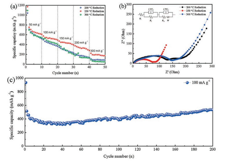
The rate capability of the Cu-SnO2 (200), Cu-SnO2 (250) and Cu-SnO2 (300) composites at different current rates is evaluated in Fig. 4a. Cu-SnO2 (200), Cu-SnO2 (250) and Cu-SnO2 (300) composite electrodes were tested at different rates from 50 mA/g to 300 mA/g. The specific capacity of Cu-SnO2 (200) and Cu-SnO2 (300) expressed pretty low value when the discharge current density was more than 150 mA/g. In agreement with material characterization results, low reduction temperature caused parts of Cu6Sn5 to remain so that Cu-SnO2 (200) shown poor rate capability. On the contrary, the rate capability was also unsatisfactory when the reduction temperature was reaching to 300 ℃, due to the increasing Cu crystal size and aggregating SnO2. While, with 3D metal cluster and nanovoids, Cu-SnO2 (250) electrode shown the highest specific capacity of 176.8 mAh/g at a current density of 300 mA/g.

|
Download:
|
| Fig. 4. Electrochemical behavior of Cu-SnO2 (200), Cu-SnO2 (250) and Cu-SnO2 (300) composites: (a) Rate capability with different rates from 50 mA/g to 300 mA/g. (b) Impedance plots testing after cycling over 5 cycles at 25 ℃ at frequencies from 100 kHz to 10 mHz. The equivalent circuit is shown in the inset. (c) Cycling performance at the current density of 100 mA/g. | |
Electrochemical impedance spectroscopy (EIS) measurements were also carried out to compare the impedance differences of the as-prepared Cu-SnO2 composites. Fig. 4b shows the Nyquist plots of the electrodes at a discharge potential of 0.5 V vs. Li/Li+ at 25 ℃ after 5 cycles. The EIS spectra exhibit two compressed semicircles followed by a linear part at an approximate 45° angle to the real axis corresponds to the lithium-diffusion processes within the electrode, which provided typical SnO2 impedance curve [35, 36]. The cells with Cu-SnO2 (200), Cu-SnO2 (250), and Cu-SnO2 (300) electrode shown possess similar uncompensated resistance (Rl) (4.02 Ω, 2.67 Ω and 3.92 Ω, respectively). In contrast, the film resistance (Rf) of the SEI and the charge transfer resistance (Rct) show significant differences in the three different coin cells. The cells with Cu-SnO2 (250) shown a lower Rf (16 Ω) than those of Cu-SnO2 (200) and Cu-SnO2 (300) (80 Ω and 140 Ω, respectively), indicating the formation of a thinner SEI layer because the 3D metal cluster architecture space-confined SnO2 particles. Meanwhile, the Rct of the Cu-SnO2 (250) electrode (132 Ω) is much smaller than those of the Cu-SnO2 (200) and Cu-SnO2 (300) electrodes (258 Ω and 296 Ω, respectively). The results indicate that Li+ suffers more active kinetics and shorter diffusion path in Cu-SnO2 (250) composite than that of the Cu-SnO2 (200) and Cu-SnO2 (300) composites because of its unique architecture.
The unique 3D metal cluster architecture is responsible for the superior electrochemical properties of Cu-SnO2 (250). As can be seen from Fig. 4c, the long cycle performance was tested at 100 mA/g over the range of 3.0-0.01 V. The Cu-SnO2 (250) electrode exhibited excellent cycling stability and retained a high capacity of 536.1 mAh/g after 200 cycles at 25 ℃. It should be pointed out that the discharge capacities exhibit an ascending trend accompanied by slightly fluctuations, attributed to the SEI film formation by decomposing of the electrolyte.
In summary, Cu-SnO2 composites have been successfully synthesized via a facile solid-state synthesizing process with oxidation and reduction method, which is suitable for large batch and lowcost production. The Cu-SnO2 microparticles exhibit a novel 3D metal cluster conducting architecture, where Cu is evenly distributed in SnO2 nanoparticles. The 3D metal cluster and nanovoids caused by the reduction of CuO were restricted the pulverization of SnO2 during charge/discharge process, due to the space-confined property. With this novel structure, Cu-SnO2 particle possessed much better electrical conductivity than that of SnO2 and high theoretical capacity. The Cu-SnO2 composites show significantly improved cycling performance and rate capability compared with the Cu6Sn5 electrode due to the 3D metal cluster conducting architecture in the composites. The experimental results show that the well-designed Cu-SnO2 composite electrode has great potential as a commercial anode for LIBs.
AcknowledgmentsThe authors gratefully acknowledge the financial supports for this research from the Natural Science Foundation of Tianjin (No. 16JCYBJC41700), Tianjin Major Program of New Materials Science and Technology (Nos. 16ZXCLGX00070, 16ZXCLGX00110), Tianjin Municipal Education Committee Scientific Research Projects (No. 2017KJ075), the National Nature Science Foundation of China (No. 21676200), and Key Laboratory of Advanced Ceramics and Machining Technology, Ministry of Education (Tianjin University).
Appendix A. Supplementary dataSupplementary material related to this article can be found, in the online version, at doi:https://doi.org/10.1016/j.cclet.2018.06.017.
| [1] |
J. Mei, T. Liao, Z. Sun, J. Energy Chem. 27 (2018) 117-127. DOI:10.1016/j.jechem.2017.10.012 |
| [2] |
S. Chu, A. Majumdar, Nature 488 (2012) 294-303. DOI:10.1038/nature11475 |
| [3] |
Y. Sun, X. Liang, H. Xiang, Y. Yu, Chin. Chem. Lett. 28 (2017) 2251-2253. DOI:10.1016/j.cclet.2017.11.028 |
| [4] |
L. Ellingsen, C.R. Hung, G. Majeau-Bettez, et al., Nat. Nanotechnol. 11 (2016) 1039. DOI:10.1038/nnano.2016.237 |
| [5] |
J. Mei, T. Liao, L. Kou, Z. Sun, Adv. Mater. 29 (2017) 1700176. DOI:10.1002/adma.v29.48 |
| [6] |
J. Lu, Z. Chen, Z. Ma, et al., Nat. Nanotechnol. 11 (2016) 1031-1038. DOI:10.1038/nnano.2016.207 |
| [7] |
S. Chu, Y. Cui, N. Liu, Nat. Mater. 16 (2016) 16-22. |
| [8] |
Y. Sun, N. Liu, Y. Cui, Nat. Energy 1 (2016) 16071. DOI:10.1038/nenergy.2016.71 |
| [9] |
J. Peng, Y. Zuo, G. Li, G. Wang, Chin. Chem. Lett. 27 (2016) 1559-1562. DOI:10.1016/j.cclet.2016.02.028 |
| [10] |
J.T. Xu, J.M. Ma, Q.H. Fan, S.J. Guo, S.X. Dou, Adv. Mater. 29 (2017) 1606454. DOI:10.1002/adma.v29.28 |
| [11] |
R. Hu, Y. Ouyang, T. Liang, et al., Adv. Mater. 29 (2017) 1605006. DOI:10.1002/adma.201605006 |
| [12] |
Q. Liu, Y. Dou, B. Ruan, Chem. Eur. J. 22 (2016) 5853-5857. DOI:10.1002/chem.201505122 |
| [13] |
Q. Yang, T. Sun, J. Yu, J. Ma, Chin. Chem. Lett. 27 (2016) 412-416. DOI:10.1016/j.cclet.2015.12.025 |
| [14] |
W. Dong, J. Xu, C. Wang, et al., Adv. Mater. 29 (2017) 1700136. DOI:10.1002/adma.201700136 |
| [15] |
D. Cui, Z. Zheng, X. Peng, et al., J. Power Sources 362 (2017) 20-26. DOI:10.1016/j.jpowsour.2017.07.024 |
| [16] |
C. Cui, J. Xu, L. Wang, et al., ACS Appl. Mater. Int. 8 (2016) 8568-8575. DOI:10.1021/acsami.6b02962 |
| [17] |
M.S. Park, G.X. Wang, Y.M. Kang, et al., Angew. Chem. Int. Ed. 119 (2007) 764-767. DOI:10.1002/ange.200603309 |
| [18] |
J.H. Jeun, K.Y. Park, D.H. Kim, et al., Nanoscale 5 (2013) 8480-8483. DOI:10.1039/c3nr01964k |
| [19] |
W. Wei, F. Jia, K. Wang, P. Qu, Chin. Chem. Lett. 28 (2017) 324-328. DOI:10.1016/j.cclet.2016.09.003 |
| [20] |
R. Hu, W. Sun, H. Liu, M. Zeng, M. Zhu, Nanoscale 5 (2013) 11971-11979. DOI:10.1039/c3nr03756h |
| [21] |
C. Zhong, J. Wang, Z. Chen, H. Liu, J. Phys. Chem. C 115 (2011) 25115-25120. DOI:10.1021/jp2061128 |
| [22] |
H. Kim, S.W. Kim, Y.U. Park, et al., Nano. Res. 3 (2010) 813-821. DOI:10.1007/s12274-010-0050-4 |
| [23] |
J. Liao, C. Yuan, H. Li, et al., Nano-Micro Lett. 10 (2018) 21. DOI:10.1007/s40820-017-0172-2 |
| [24] |
H. Li, H. Zhou, Chem. Commun. 48 (2012) 1201-1217. DOI:10.1039/C1CC14764A |
| [25] |
K. Huang, B. Li, M. Zhao, et al., Chin. Chem. Lett. 28 (2017) 2195-2206. DOI:10.1016/j.cclet.2017.11.010 |
| [26] |
R. Hu, G.H. Waller, Y. Wang, et al., Nano Energy 18 (2015) 232-244. DOI:10.1016/j.nanoen.2015.10.037 |
| [27] |
H. He, W. Fu, H. Wang, et al., Nano Energy 34 (2017) 449-455. DOI:10.1016/j.nanoen.2017.03.017 |
| [28] |
L. Zu, Q. Su, F. Zhu, et al., Adv. Mater. 29 (2017) 1701494. DOI:10.1002/adma.v29.34 |
| [29] |
J. Kang, S. Zhang, Z. Zhang, Adv. Mater. 29 (2017) 1700515. DOI:10.1002/adma.v29.48 |
| [30] |
J. Chen, L. Yang, S. Fang, Z. Zhang, S. Hirano, Electrochim. Acta 105 (2013) 629-634. DOI:10.1016/j.electacta.2013.05.052 |
| [31] |
K.D. Kepler, J.T. Vaughey, M.M. Thackeray, J. Power. Sources 81-82 (1999) 383-387. DOI:10.1016/S0378-7753(99)00111-1 |
| [32] |
Q. Han, Z. Yi, Y. Cheng, Y. Wu, L. Wang, RSC Adv. 6 (2016) 15279-15285. DOI:10.1039/C5RA23788B |
| [33] |
B. Lu, R. Hu, J. Liu, et al., RSC Adv. 6 (2016) 13384-13391. DOI:10.1039/C5RA23988E |
| [34] |
Y.J. Mai, X.L. Wang, J.Y. Xiang, et al., Electrochim. Acta 56 (2011) 2306-2311. DOI:10.1016/j.electacta.2010.11.036 |
| [35] |
J. Liang, X. Gao, J. Guo, et al., Sci. China Mater. 61 (2018) 30-38. DOI:10.1007/s40843-017-9119-2 |
| [36] |
Z. Zhang, Y. Wang, S. Chou, et al., J. Power Sources 280 (2015) 107-113. DOI:10.1016/j.jpowsour.2015.01.092 |