 2018, Vol. 29


b Department of Hydraulic Engineering, Tsinghua University, Beijing 100084, China;
c Department of Chemical Science and Engineering, Tokyo Institute of Technology, Yokohama 226-8502, Japan
The development of functional nanostructured materials is currently one of the most active research fields [1-7]. Carbon nanotubes (CNTs) are hollow nano-sized tubes of concentric graphitic carbon capped by fullerene-like hemispheres [8]. Since its discovery in 1991, CNTs with unique properties, such as high electrical conductivity, superior chemical and mechanical stability, and large surface area [9, 10] are one kind of the most promising materials for applications in many scientific and technological fields such as actuation [11, 12], catalytic membranes [13, 14], polymer composites [15, 16], electrochemical energy conversion [17] and storage devices [18-21] and biological systems [22, 23]. However, due to the strong van der Waals interactions between tubes, CNTs tend to precipitate into ropes or bundles in the solution resulting in a phase separation. In order to be used in the solution processes as their unique properties, it is necessary to tailor the chemical nature of the nanotube's wall to solubilize and separate discrete CNT molecules from the tight bundles. For this purpose, several approaches have been developed for the surface modification of CNTs including chemical functionalization using strong acids treatment [24], covalent attachment of functional groups to the walls of the nanotubes [25], and wrapping nanotubes with surfactants or polymers [26-28]. Among them, the non-covalent polymer wrapping method has the advantage of being a mild procedure which avoids the usage of strong acids and has less destructive to the intrinsic properties of CNT [29].
Due to the high surface area-to-volume ratios and good interface-dominated properties gold (Au) nanoparticles have been widely employed as a catalyst [30]. Nanoparticles (NPs) and CNTs composite possess interesting synergistic properties [31] and have been used to fabricate electrochemical sensors and biosensors. Gold NPs and CNTs composite modified electrodes have been employed to detect glucose [32, 33], DNA [34] and arsenic(Ⅲ) [35]. Owing to their excellent properties Au/CNTs composite catalysts have attracted intensive attention.
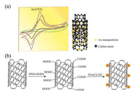
In this paper, nano gold particles loaded carbon nanotubes (nano-Au/CNTs) composite catalysts were prepared by a new method with a mixed acids treatment process and their electrochemical properties were investigated (Fig. 1). Here, Nafion was used to adhere a nano-Au/CNTs composite catalyst supported on CNTs to the treated glass carbon electrode. The gas electrode is composed of a reference electrode and a counter electrode to form a "gas-electric" and detect gas during a production process. The resulting electrode is fast and convenient.

|
Download:
|
| Fig. 1. (a) Schematic diagram of Au/CNTs composite catalyst for electrochemical properties study. (b) Preparation of Au/CNTs composite catalyst. Modification of CNTs with HNO3 and H2SO4 solution then with HAuCl4-EG solution reaction. | |
Chloroauric acid, HNO3, H2SO4, ethylene glycol (EG), sodium hydroxide, red blood salt, Nafion solution (99%, DuPont) and CNTs (99.99%, Japan) were used as solutions and materials. The CNTs were pre-activated before the preparation of nano-Au/CNTs composite catalysts according to following procedure. 1.0 g CNTs were added to a mixture solution of HNO3 and H2SO4 (1:3, v/v) in a 100 mL three-necked flask at 120 ℃ for 5 h under an oil bath and then cooled to room temperature. And then the CNTs solutions were filtered and washed with deionized water to neutrality and dried at 80 ℃. The Au/CNTs composite catalysts were prepared according to the following procedure. 50 mg of activated CNTs were suspended in EG and then ultrasonicated for 20 min to disperse the CNTs. Then, 16.42 mg chloroauric acid was dropped in and processed with ultrasonication for 20 min. The HAuCl4-EG solution was dispensed into the supernatant of CNTs-EG. Then oil bathed at 150 ℃ and stirred for 1.0 h, and then cooled to room temperature, filtered, washed with neutral deionized water and dried at 80 ℃ for several hours.
Powder X-ray diffraction (XRD, RINT 2200 V/PC, Cu Kα) was employed to monitor the phase formation. X-ray photoelectron spectroscopy (XPS) analysis was conducted with a Thermo VG RSCAKAB 250X X-ray photoelectron spectrometer. Fourier transform infrared (FTIR) spectroscopy was recorded on a Perkin Elmer Spectrum 100 FTIR spectrometer in transmission mode using a KBr wafer. Transmission electron microscopy (TEM) was studied on a JEOL 3010 transmission electron microscope. Difference thermal analysis (DTA) was performed using a Rigaku Thermo Plus TG 8120 system. Cyclic voltammetry scans were performed using a Model 273 electrochemical workstation (Princeton) at a scanning potential of -0.2 V–1.0 V with a scanning rate of 10 mV/s at an electrolyte of 5 mmol/L potassium ferricyanide.
Au/CNTs composite catalyst deposition: Glassy carbon electrode (polished and washed with distilled water in advance) was immersed in ethanol and ultrasonicated for 5 min and then washed with distilled water. 10 mg of the Au/CNTs composite catalyst was dissolved in a mixed solution of 2 mL of ethanol and 100 mL of Nafion. This was separated by ultrasonication for 0.5–1.0 h. The Au/ CNTs composite catalyst was added dropwise onto the glassy carbon electrode for cyclic voltammetry measurement.
Fig. 2a shows the XRD patterns of powder CNTs before and after acid treatment. It indicates the mixed acid treatment does not destroy the main structure of the CNTs as there was no change in the diffraction patterns. Fig. 2b shows the FTIR spectra before and after acid treatment of the CNTs. The spectral lines at 1625 cm-1 and 3434.3 cm-1 are due to the characteristic vibrations of carbonyl and hydroxyl groups. The peak at around 1570 cm-1 is assigned to the characteristic reflection of —C=O and —OH functional groups. This observation indicates the CNTs are oxidized under strong and acidic oxidants and their surfaces are introduced —C=O and —OH groups, which is consistent with the literature [36]. The production of the —C=O and —OH functional groups is beneficial for Au nanoparticle deposition.

|
Download:
|
| Fig. 2. X-ray diffraction patterns and FTIR spectra of CNTs, (a) X-ray diffraction patterns of CNTs before and after pretreating, (b) FTIR spectra of CNTs before and after pretreating with a mixed acid. | |
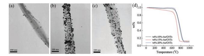
Fig. 3a shows the XRD patterns of Au/CNTs with 15% Au loading at different pH. The average particle size of Au nanoparticles was calculated by the diffraction peak data of gold (111) plane and the Sherrer Formula (1):
|
(1) |
Where K = 0.89, λ = 1.54178, β is the half-width height, and θ is the diffraction angle. Here, Da = 28.06 nm; Db = 18.42 nm; Dc = 12.31 nm; Dd = 12.74 nm. The CNTs surface area increases as the gold particles become smaller. The results show that the pH affects particle size after loading. The size decreased at pH 9–10. When the pH value is over 10, the size increased. Thus, follow-up experiments used pH 10 as the experimental conditions.
The process of loading Au nanoparticles onto the surface of CNTs conforms to the kinetic model, which is affected by many factors such as time, temperature, concentration, pH, etc. The optimal reaction conditions were obtained by adjustment with the single variable principle, which were identified through XRD, TEM, TG, XPS. During deposition, EG is taken as the reducing agent and the solvent. Fig. 3b shows the XRD pattern of the 15% Au nanoparticles deposited CNTs. The characteristic peaks of crystalline CNTs and Au could be clearly observed indicates the Au nanoparticles deposition does not break the crystal structure of CNTs. Fig. 3c shows the XPS patterns of the Au nanoparticles deposited CNTs. The peaks at 84.30 eV (Au 4f7/2) and 87.96 eV (Au 4f5/2) correspond to the Au of zero valence Au, which indicates that Au is indeed loaded in the CNTs.

|
Download:
|
| Fig. 3. Effect of conditions on particle load. (a) XRD patterns of Au/CNTs as a function of pH, (b) XRD results of carbon nanotube loading on Au nanoparticles, (c) XPS patterns of Au/CNTs. | |
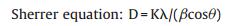
TEM and TG were used to study the effects of different loading at 10%, 15% and 20% loading on Au/CNTs (Fig. 4). EG is the reducing agent and solvent with the solution pH set at 10. The reaction temperature is lower than the boiling point of ethylene glycol. Reflux condensation was used when the temperature of the oil bath reached 150 ℃. The solution was then continuously heated and stirred within 1 h. Next, it was cooled to room temperature, filtered, and washed with deionized water to neutrality. Finally, TEM and TG analyses were done after 80 ℃ drying.

|
Download:
|
| Fig. 4. Comparison of loading conditions. Typical TEM images of Au/CNTs with loading of (a) 10%, (b) 15% and (c) 20%. (d) TG curve of Au/CNTs under different loads. | |
Our previous experiments used 15% loading, but a low load rate could affect the catalytic performance. Hence, we studied the catalytic performance at different load rates (10%, 15%, and 20%). We hope that the actual load will not differ much from the calculated load. However, according to the TEM micrograph (Figs. 4a–c), the loaded amount of Au nanoparticles at a 10% load rate is obviously less than that of 15% and 20%. The Au nanoparticles loaded on CNTs of 15% shows higher uniform dispersion than that of 20% as observed from the TEM photos. Fig. 4b shows a typical TEM image of Au/CNTs with 15% Au loading. The nano-Au particles loaded on the out-surface of CNTs were clearly observed, which indicates Au nanoparticles were deposed on the out-surface of CNTs. For showing the actual loaded amount of loaded Au nanoparticles, the TG curves are shown in Fig. 4d. The data show that when the calculated load rate is 10%, the actual loading amount is 14%. When the calculated load rate is 15%, the actual load is 12%. When the calculated load is at 20%, the actual load is 11%. This is likely because of loss of CNTs, which leads to the actual load being higher than the theoretical load. Thus, the results of loading at 20% load rate should be 20%, but is actually 11%. This is not consistent with the theory because gold loading has a limit, and 20% has already exceeded this limit. The better uniform dispersion also could be proved from the TG measurement result shown in Fig. 4d. The temperature for the compound weight starting decreasing is lower than that at 10% and 15%. As worse dispersion leads to particle aggregation that needs much higher temperature to strip the particle. Because of the better dispersibilty of nano-Au load at 15%, which might show better electrochemical catalytic performance, hence the following experiments, nano-Au/CNTs at load rate of 15% was selected as the working electrodes.
Fig. 5 shows the cyclic voltammetry polarization curves of different working electrodes. The working electrode of Au/CNTs (15%) shows the highest peak and obviously larger electrochemical active area followed than that of CNTs and blank glassy carbon, which indicate the Au/CNTs composite catalysts show better electrochemical catalytic performance. The Au/CNTs show narrower potential window than CNTs and blank electrodes, this is might due to the obtained new polar groups and defects on the surface of the prepared CNTs by a mixed acids treatment process. Further work for investigating the interaction between the nanoAu and CNTs, and the polar groups defects formation mechanism on CNTs are under operating.

|
Download:
|
| Fig. 5. Cyclic voltammetry of different working electrodes. | |
In summary, nano-Au/CNTs were prepared by a new method and the Au nanoparticles were dispersed on the surface of the CNTs. The particle size of the Au nanoparticles was controlled by pH value; e.g., at pH 10, the particle size of Au nanoparticles was about 10 nm, which shows the optimum loading rate of 15%. The cyclic voltammetry measurements showed the obtained Au/CNTs composite catalyst could significantly increase the electron transport. The ethylene glycol reduction method established here offers a new method for the preparation of Au/CNTs composite catalyst.
AcknowledgmentThis work was supported by the China Postdoctoral Science Foundation (No. 2017M620048).
| [1] |
B. Li, P. Gu, Y. Feng, et al., Adv. Funct. Mater. 27 (2017) 1605784. DOI:10.1002/adfm.v27.12 |
| [2] |
H. Pang, Y. Zhang, Z. Run, W. Lai, W. Huang, Nano Energy 17 (2015) 339-347. |
| [3] |
Y. Lu, B. Li, S. Zheng, et al., Adv. Funct. Mater. 27 (2017) 1703949. DOI:10.1002/adfm.v27.44 |
| [4] |
S. Zheng, H. Xue, H. Pang, Coord. Chem. Rev. 375 (2018) 2-21. DOI:10.1016/j.ccr.2017.09.021 |
| [5] |
L. Lin, M. Lai, H. Li, et al., Rsc Adv. 7 (2017) 29639-29644. |
| [6] |
M. Jie, S. Mao, H. Li, J.M. Lin, Chin. Chem. Lett. 28 (2017) 1625-1630. DOI:10.1016/j.cclet.2017.05.024 |
| [7] |
Y. Li, Y. Zheng, D. Zhang, et al., Chin. Chem. Lett. 28 (2017) 184-188. DOI:10.1016/j.cclet.2016.07.020 |
| [8] |
S. Lijima, Nature 354 (1991) 56-58. DOI:10.1038/354056a0 |
| [9] |
D. Tasis, N. Tagmatarchis, A. Bianco, M. Prato, Chem. Rev. 106 (2006) 1105-1136. DOI:10.1021/cr050569o |
| [10] |
R.H. Baughman, A.A. Zakhidov, W.A.D. Heer, Science 297 (2002) 787-793. DOI:10.1126/science.1060928 |
| [11] |
T. Mirfakhrai, J. Oh, M. Kozlov, et al., Smart Mater. Struct. 16 (2015) S243-S249. |
| [12] |
M.D. Lima, N. Li, A.M. dJung, et al., Science 338 (2012) 928-932. DOI:10.1126/science.1226762 |
| [13] |
J.K. Holt, H.G. Park, Y. Wang, et al., Science 312 (2006) 1034-1037. DOI:10.1126/science.1126298 |
| [14] |
R. Smajda, Kukovecz Á., Z. Kónya, I. Kiricsi, Carbon 45 (2007) 1176-1184. DOI:10.1016/j.carbon.2007.02.022 |
| [15] |
M.T. Byrne, Gun'Ko Y.K., Adv. Mater. 22 (2010) 1672-1688. DOI:10.1002/adma.v22:15 |
| [16] |
W. Bauhofer, J.Z. Kovacs, Compos. Sci. Technol. 69 (2009) 1486-1498. DOI:10.1016/j.compscitech.2008.06.018 |
| [17] |
H. Beitollahi, H. Khabazzadeh, H. Karimi-Maleh, A. Akbari, Chin. Chem. Lett. 23 (2012) 719-722. DOI:10.1016/j.cclet.2012.03.034 |
| [18] |
M. Michel, A. Taylor, R. Sekol, et al., Adv. Mater. 19 (2010) 3859-3864. |
| [19] |
R.S. Morris, B.G. Dixon, T. Gennett, R. Raffaelle, M.J. Heben, J. Power Sources 138 (2004) 277-280. DOI:10.1016/j.jpowsour.2004.06.014 |
| [20] |
M. Sathiya, A.S. Prakash, K. Ramesha, J.M. Tarascon, A.K. Shukla, J. Am. Chem. Soc. 133 (2011) 16291-16299. DOI:10.1021/ja207285b |
| [21] |
K. Hemalatha, A.S. Prakash, K. Guruprakash, M. Jayakumar, J. Mater. Chem. A 2 (2014) 1757-1766. DOI:10.1039/C3TA13352D |
| [22] |
T. Ramanathan, F.T. Fisher, R.S. Ruoff, L.C. Brinson, Chem. Mater. 17 (2005) 1290-1295. DOI:10.1021/cm048357f |
| [23] |
F. Picaud, C. Girardet, Surf. Sci. 602 (2008) 235-240. |
| [24] |
S.W. Lee, B.S. Kim, S. Chen, S.H. Yang, P.T. Hammond, J. Am. Chem. Soc. 131 (2009) 671-679. DOI:10.1021/ja807059k |
| [25] |
Y.S. Gao, L.P. Wu, K.X. Zhang, et al., Chin. Chem. Lett. 26 (2015) 613-618. DOI:10.1016/j.cclet.2014.11.032 |
| [26] |
J. You, J. Cao, S. Chen, Y. Wang, Chin. Chem. Lett. 28 (2017) 201-205. DOI:10.1016/j.cclet.2016.06.039 |
| [27] |
J.T. Sun, C.Y. Hong, C.Y. Pan, Polym. Chem. 2 (2011) 998-1007. DOI:10.1039/c0py00356e |
| [28] |
T. Fujigaya, N. Nakashima, Sci. Technol. Adv. Mat. 16 (2015) 024802. DOI:10.1088/1468-6996/16/2/024802 |
| [29] |
P. Liu, J. Eur. Polym. 41 (2005) 2693-2703. DOI:10.1016/j.eurpolymj.2005.05.017 |
| [30] |
S. Liu, X. Zhou, M. Zhang, et al., Chin. Chem. Lett. 27 (2016) 843-846. DOI:10.1016/j.cclet.2016.01.019 |
| [31] |
L. Liu, Y. Song, L. Wang, et al., Environ. Eng. Sci. 29 (2012) 59-63. DOI:10.1089/ees.2011.0013 |
| [32] |
Y. Liu, S. Wu, H. Ju, L. Xu, Electroanalysis 19 (2010) 986-992. |
| [33] |
J. Manso, M.L. Mena, P. Yáñez-Sedeño, J. Pingarrón, J. Electroanal. Chem. 603 (2007) 1-7. DOI:10.1016/j.jelechem.2007.02.004 |
| [34] |
S.H. Lim, J. Wei, J. Lin, Chem. Phys. Lett. 400 (2004) 578-582. DOI:10.1016/j.cplett.2004.11.023 |
| [35] |
L. Xiao, G.G. Wildgoose, R.G. Compton, Anal. Chim. Acta 620 (2008) 44-49. DOI:10.1016/j.aca.2008.05.015 |
| [36] |
C. Tan, F. Wang, J. Liu, et al., Mater. Lett. 63 (2009) 969-971. DOI:10.1016/j.matlet.2008.12.046 |